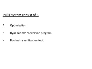
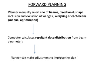
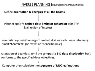
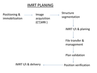
This document provides an overview of Intensity Modulated Radiotherapy (IMRT). It discusses the shift from conventional to conformal radiotherapy using improved imaging and planning techniques. IMRT allows customization of radiation dose distributions through non-uniform beam intensities achieved using dynamic multileaf collimators or compensators. The clinical implementation of IMRT requires treatment planning and delivery systems. IMRT offers advantages over conventional radiotherapy for many cancer types and its use has increased substantially in recent decades.
Conventional radiotherapy treatments are delivered with radiation beams that are of uniform intensity across the field (within the flatness specification limits). Wedges or compensators are used to modify the intensity profile to offset contour in irregularities and produce more uniform composite dose distributions such as in techniques using wedges. This process of changing beam intensity profile to meet the goals of a composite plan is called intensity modulation
IMRT refers to a radiation therapy technique in which nonuniform fluence is delivered to the patient from any given position of the treatment beam to optimize the composite dose distribution. The optimal fluence profiles for a given set of beam directions are determined through inverse planning. The fluence files thus generated are electronically transmitted to the linear accelerator, which is computer controlled, to deliver intensity modulated beams (IMBs) as calculated.
A summary of recent innovations in radiation oncology focussing on the priniciples of different techniques and their application. An overview of clinical results has also been given
The vmat vs other recent radiotherapy techniquesM'dee Phechudi
VMAT is a new type of intensity-modulated radiation therapy (IMRT) treatment technique that uses the same hardware (i.e. a digital linear accelerator) as used for IMRT or conformal treatment, but delivers the radiotherapy treatment using a rotational or arc geometry rather than several static beams.
This technique uses continuous modulation (i.e. moving the collimator leaves) of the multileaf collimator (MLC) fields, continuous change of the fluence rate (the intensity of the X rays) and gantry rotation speed across a single or multiple 360 degree rotations
This seminar is presented as a part of weekly journal club and seminar presented in Apollo Hospital,Kolkata Department of Radiation Oncology.This seminar is moderated by Dr Tanweer Shahid.
The vital importance of imaging techniques in radiation oncology now extends beyond diagnostic evaluation and treatment planning. Radiotherapy requires input from imaging for treatment planning and execution, when the treatment target is not located on the surface and, inspection and visual confirmation are not feasible. Traditional radiotherapy practices incorporate use of anatomic surface landmarks as well as radiologic correlation with 2D imaging in the form of port films or fluoroscopic imaging. Targets to be irradiated and normal tissues to be spared are delineated on CT scans in the planning process. Recent technical advances have enabled the integration of various imaging modalities into the everyday practice of radiotherapy directly at the linear accelerator. IGRT seeks to address geometric uncertainties in dose placement for target and normal tissues. It has become a routine part of current RT practice. Safe application of IGRT technology requires additional training and careful integration into the clinical process. IGRT reveals changes in anatomy during treatment which challenges conventional practices. IGRT facilitates the precise application of specialized irradiation techniques with narrow safety margins to radiosensitive organs.
Richard's aventures in two entangled wonderlandsRichard Gill
Since the loophole-free Bell experiments of 2020 and the Nobel prizes in physics of 2022, critics of Bell's work have retreated to the fortress of super-determinism. Now, super-determinism is a derogatory word - it just means "determinism". Palmer, Hance and Hossenfelder argue that quantum mechanics and determinism are not incompatible, using a sophisticated mathematical construction based on a subtle thinning of allowed states and measurements in quantum mechanics, such that what is left appears to make Bell's argument fail, without altering the empirical predictions of quantum mechanics. I think however that it is a smoke screen, and the slogan "lost in math" comes to my mind. I will discuss some other recent disproofs of Bell's theorem using the language of causality based on causal graphs. Causal thinking is also central to law and justice. I will mention surprising connections to my work on serial killer nurse cases, in particular the Dutch case of Lucia de Berk and the current UK case of Lucy Letby.
What is greenhouse gasses and how many gasses are there to affect the Earth.moosaasad1975
What are greenhouse gasses how they affect the earth and its environment what is the future of the environment and earth how the weather and the climate effects.
This pdf is about the Schizophrenia.
For more details visit on YouTube; @SELF-EXPLANATORY;
https://www.youtube.com/channel/UCAiarMZDNhe1A3Rnpr_WkzA/videos
Thanks...!
Seminar of U.V. Spectroscopy by SAMIR PANDASAMIR PANDA
Spectroscopy is a branch of science dealing the study of interaction of electromagnetic radiation with matter.
Ultraviolet-visible spectroscopy refers to absorption spectroscopy or reflect spectroscopy in the UV-VIS spectral region.
Ultraviolet-visible spectroscopy is an analytical method that can measure the amount of light received by the analyte.
A brief information about the SCOP protein database used in bioinformatics.
The Structural Classification of Proteins (SCOP) database is a comprehensive and authoritative resource for the structural and evolutionary relationships of proteins. It provides a detailed and curated classification of protein structures, grouping them into families, superfamilies, and folds based on their structural and sequence similarities.
Multi-source connectivity as the driver of solar wind variability in the heli...Sérgio Sacani
The ambient solar wind that flls the heliosphere originates from multiple
sources in the solar corona and is highly structured. It is often described
as high-speed, relatively homogeneous, plasma streams from coronal
holes and slow-speed, highly variable, streams whose source regions are
under debate. A key goal of ESA/NASA’s Solar Orbiter mission is to identify
solar wind sources and understand what drives the complexity seen in the
heliosphere. By combining magnetic feld modelling and spectroscopic
techniques with high-resolution observations and measurements, we show
that the solar wind variability detected in situ by Solar Orbiter in March
2022 is driven by spatio-temporal changes in the magnetic connectivity to
multiple sources in the solar atmosphere. The magnetic feld footpoints
connected to the spacecraft moved from the boundaries of a coronal hole
to one active region (12961) and then across to another region (12957). This
is refected in the in situ measurements, which show the transition from fast
to highly Alfvénic then to slow solar wind that is disrupted by the arrival of
a coronal mass ejection. Our results describe solar wind variability at 0.5 au
but are applicable to near-Earth observatories.
2. • To achieve Goal of Radiotherapy.
• During past decades, with advances in radiological imaging
and computer technology.
Shift from Conventional to conformal radiotherapy
3. • Conventional RT:- Irradiation of pt with few beam direction, all
beam are aimed at single point denoted as isocenter.
• Radiation shape from each beam are manually drawn on the
projected 2D images taken from an Xray Simulator.
• Difference in conventional and conformal is planning CT is used to
to define tumor volume and to design treatment portal accordingly
• Conformal RT: 3DCRT & IMRT
• Transition from 3DCRT to 4DRT.
4. • IMRT was Proposed over 50 years ago by Takahashi in Japan
(Takahashi et al).
• 1st attempted in the late 1960s by Hellman and colleagues .
• In mid-1990s, IMRT began to be used in different academic
centers.
• Not till the late 1990s with the availability of commercial
treatment planning systems did IMRT start to become widely
available
5. • In the 2002 survey, 32%of radiation oncologists were using
IMRT.“(Mell LK, Roeske JC, Mundt AJ. Cancer2003;204-211)
• In the 2004 survey, this percentage increased to 74%.
(Mell LK, MehrotraAK, Mundt AJ. Cancer2005;104:1296)
• While commonly available, it is being used to treat only a subset
of patients at most centers.
6. • Process of changing beam intensity profile to achieve
composite plan is called intensity modulation.
INTENSITY MODULATORS
- Compensators
- Wedges
- Dynamic Multileaf collimators
7. Intensity modulated radiotherapy:-
• It’s a technique in which non uniform fluence is delivered to the
patient from any given position of the treatment beam to optimize
the composite dose distribution.
• It assigns non uniform intensity/weights to tiny subdivision of
beams ( a.k.a rays or beamlets)
• Permits greatly increased control over the radiation fluence
,enabling custom design of optimum dose distributions.
8. The clinical implementation of IMRT requires at least two
systems:
• Treatment planning computer system that can calculate non
uniform fluence maps for multiple beams directed from
different directions to maximize dose to the target volume while
minimizing dose to the critical normal structures.
• System of delivering the non uniform fluences as planned.
9. IMRT system consist of :-
• Optimization
• Dynamic mlc conversion program
• Dosimetry verification tool.
10. FORWARD PLANNING
Planner manually selects no of beams, direction & shape
inclusion and exclusion of wedges , weighing of each beam
(manual optimization)
Computer calculates resultant dose distribution from beam
parameters
Planner can make adjustment to improve the plan
11. INVERSE PLANNING (PROPOSED BY BRAHME IN 1988)
Define orientation & energies of all the beams
Planner specify desired dose limits(or constraint ) for PTV
& all region of interest
computer optimization algorithm first divides each beam into many
small “beamlets” (or “rays” or “pencil beams”)
Alteration of beamlets until the composite 3-D dose distribution best
conforms to the specified dose objectives.
Computer then calculate the sequence of MLC leaf motions
13. POSITIONING AND IMMOBLIZATION
• Highly conformal nature of the IMRT.
• Techniques to reduce or follow the internal organ movement.
• Patient comfort.
14.
15.
16.
17. IMAGE ACQUISITION
• Goal of treatment should be discussed.
• For Inverse planning a CT scan is required .
• Slice spacing not more than 5 mm.
• Different Imaging modality may required to identify the correct
target volume and OAR (CECT,MRI,PET, etc) called as image
augmentation
• Should be compatible with the available treatment planning
system.
18. STRUCTURE SEGMENTATION or Image segmentation
• Most important and critical step
• The success of IMRT is closely tied to the accuracy of the target and
OAR delineation
• Department should develop a protocol.
• Should follow the guidelines (RTOG, relevant atlas ).
• ICRU 50,62 should be used for the nomenclature, Prescribing,
Recording, and Reporting.
19.
20. TREATMENT PLANNING
• Beam energy , No of beams and orientation
• Isocenter placement (ICRU Reference point)
• Min Dose, Max Dose, Dose volume ( Biological Constrains)
• Optimization – Fluence Modulation
• Deliverability ( Reasonable MU, Treatment time)
• Final dose calculation( Dose grid size, algorithm)
21. PLAN EVALUATION
• IMRT/VMAT plans needs to evaluated very carefully
• Inspecting and Comparing DVH is useful.
• Planner needs to be inspect the Isodose in each slice.
• Is the dose uniformity in the target acceptable?
• Are the stated plan goals for the hot spots and target coverage
satisfied?
• Are the stated plan goals for normal tissue sparing satisfied?
• Is the organs contoured entirely or not ?
22. Characteristic of MLCs
The design system of MLC differ in many ways with respect to
their manufacturer:-
a> Location of MLC relative to the conventional Jaws
b> Single focused or double focused MLCs( Elekta & Varian are
single foccused)
c> Physical characteristic or shape of the leaves
d> Leaf movement restrictions
e> Maximum achievable field size
23. Advantage : Smaller and lighter MLC design with physical
clearance between gantry head and patient
24.
25.
26. • Most MLCs have cutting tongue and groove pattern on the
side of leaves
• It reduces the radiation leakage
29. GENERATION OF LEAF MOTION FILES :-
• “Leaf sequencer” is an algorithm that translates the beam intensity
pattern produced by the IP system into an instruction set describing
how to move the MLC leaves during beam delivery.
• Result of optimization may be either continuous 2-D intensity
profiles, or discrete 2-D intensity matrices with discrete resolution.
• DMLC delivery (referred to as a sliding window) delivers a
continuous 2-D intensity profile, whereas STATIC delivery (referred
to as step & shoot) results in “discretized” intensity patterns.
30. ADVANTAGE OF STATIC MLC :-
• Advantages of static, or step-and-shoot, IMRT are that it is
conceptually simple, there are no requirements to control the
individual leaf speeds (thus simplifying the MLC control system) or
delivery dose rate.
• Interrupted treatment is easy to resume, easy to verify an intensity
pattern for each field, and fewer MUs are required in comparison
with DMLC delivery.
DISADVANTAGE OF STATIC MLC :-
• Require prolonged treatment time, particularly for complex
intensity patterns
31. ADVANTAGE OF DYNAMIC MLC :-
• The advantage of DMLC delivery is that it can deliver a smoothly
varying intensity profile.
DISADVANTAGE OF DYNAMIC MLC :-
• Delivery mechanism is rather complicated, involving leaf-speed
and dose-rate modulation
• Requires the precise control of individual leaf speeds; and small
errors in the calibration of leaf position could (for very highly
modulated fields) result in significant errors in delivered doses
32. • IMRT is becoming a mature technology, and is widely applied
to many cancer sites.
• Many treatment-planning comparison studies have
demonstrated the clear dosimetric advantages of IMRT.
• Clinical results from the past decade have shown the
improvement of local tumor control and reduction of
treatment toxicities for prostate cancer, head and neck
cancer, and other cancers.
IMRT Utilization
33. Site %
Prostate 85%
Head and neck 80%
CNS 64%
Gynecology 35%
Breast 28%
GI 26%
Sarcoma 20%
Lung 22%
Pediatrics 16%
Lymphoma 12%
IMRT PRACTICE SURVEY (2004) TOP TREATED SITES
Mell LK, Mundt AJ. Survey of IMRT Use in the USA-2004 Cancer 2005;104:1296
34. Volume modulated arc therapy
• Radiation dose is delivered to the tumor while simultaneously
moving the MLCs leaves and the gantry.
• Both the dose rate and gantry speed vary in this system.
• Advantage: a> excellent dose distribution in deep seated
tumors
b> faster delivery
c> Reduction of MUs ( decreasing the risk of secondary cancer)
35. Image guided radiotherapy
• IGRT = IMRT with image guidance
• Goal of IGRT is to eliminate or reduce the uncertanities
associated with target volume defination and it
intrafractional and interfractional organ motion
• 4DCT, 4DPETCT , 4D-CBCT are applied to R.T guidance and
verification
• Respiratory gated IMRT
36. RESPIRATORY GATING WITH IMRT
•Cancers that are subject to tumor motion during respiration benefit
from respiratory gating.
•Internal structures can move a significant amount- The diaphragm
and liver can move up to 3 cm and the pancreas, kidney and thorax
can move up to 2 cm
•Respiratory gating is used to minimize the increased margins of the
treatment volume that are directly related to respiratory movements
37. •Cancers that are subject to tumor motion during respiration benefits
from respiratory gating.
•These include lung, breast, pancreatic, stomach, liver, and prostate .
•Breast cancers are usually treated at the point of maximum
inhalation because this increases the lung volume, decreasing the
amount of lung tissue in the field.
38. TRACKING RESPIRATION
•Respiratory gating uses marker systems that “learn” the patient’s
respiratory pattern.
EXTERNAL MARKER INTERNAL MARKER
• RPM by varian.
• Reflective marker learns
patients breathing pattern.
• Camera system
- sends signal
- reflected off markers
- respiratory wave form
created
• Implanted gold seeds
• Use fluoroscopy to
locate
39. •The most commonly used marker is an external marker known as the
Real-time Position Management (RPM) system by Varian.
•It’s a little plastic box with two reflective markers normally placed
halfway between the patient’s xyphiod and
Navel in order to take advantage of the
Greatest external displacement.
•A camera located near the foot of the table sends a signal that is
reflected off the metallic markers and translated into a waveform whose
shape represents the patient’s movement with regard to the respiratory
cycle.
•Implanted gold seeds are internal markers that require a surgical
procedure for placement. During simulation and treatments they are
tracked in real-time using flouroscopy.
Real time positioning system
41. •Treatment plans are formed using the respiratory waveform and the
CT images
•The treatment plan is designed to place the treatment field around the
target volume during a specific phase of the respiratory cycle.
•For most treatment plans, the beam on time correlates with
exhalation because the anatomy is in relatively the same position for
the greatest period of time.
43. Dose calcuation algorithm
• More complex the intensity modulation, more will be
the M.U required
• One time monte carlo calculation of pencil beam
algorithm is used.
44. Quality assurance ( American association of
physicist in medicine report 82 ,2003
• Simple daily film QA
• EPID
• Dosimetric test
45. Frequency Procedures Tolerance
Before first t/t Individual field
verificaiton and plan
verification
3%
Daily Dose to test point in each
IMRT field
3%
Weekly Static Vs sliding window
field dose distribution
3%
Annually All commissioning
procedure: leaf stability,
speed , leaf acceleration,
MLCs , leaf position, static
Vs sliding window field
3%
IMRT Quality Assurance Program
46. IMRT IN HEAD AND NECK CANCER
• Variable numbers of co planar beams are used(5-15)
• Maintain target and nodes coverage as in conventional t/t
• Keep dose to cord and brainstem tolerable.
• Reduce dose to parotid as much as possible.
• Concomitant boost can be done in single plan ,there is no
need of subsequent electron boost.
47. • Eisbruch et al (1999): A mean parotid dose of < 26 Gy
should be planning goal.
• Eisbruch et al (2007): Substantial parotid flow recovery
(upto 86% of pretreatment levels) at 2 years if mean
doses are between 25-30Gy.
• Eisbruch et al (2010): Severe xerostomia (<25% of
baseline) avoided if mean parotid dose kept to <20Gy
(if one parotid is to be spared) or <25 Gy (if both are to
be spared)
Parotid dose and xerostomia
48. CONCLUSION
• Avoidance of circumferential irradiation of rectum to 55Gy with
minimal compromise of PTV coverage is achievable with IMRT ƒ.
• use of IMRT reduces acute GI/GU toxicity rate when compared with
the 4FB technique.
IN HEAD AND NECK CANCER:-
• IMRT plan show improve dose distribution especially sparing of
parotids.
• Plans with more beams is better than with less beams, however
improvement saturates after beyond certain number of beams.
plan quality deteriorates when beam number is <=5.
IN PROSTATE:-