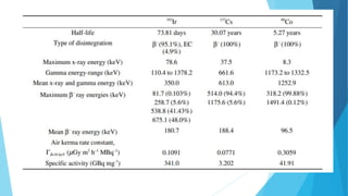
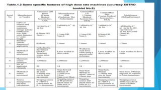
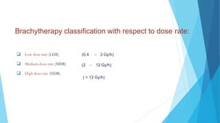
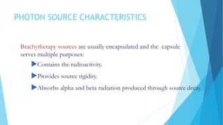
BRACHYTHERAPY
1. Introduction
2. Photon source characteristics
3. Clinical use and dosimetry systems
4. Dose specification and reporting
5. Dose distribution around sources
Introduction
 Brachytherapy(also referred to as Curietherapy) is
defined as a short-distance treatment of malignant
disease with radiation emanating from small sealed
(encapsulated) sources.
 The sources are placed directly into the treatment
volume or near the treatment volume.
Introduction
 Brachytherapy compared to external beam therapy:
Advantages of brachytherapy
Improved localized dose delivery to the target
Sharp dose fall-off outside the target volume
Better conformal therapy
Disadvantages of brachytherapy
Only good for well localized tumors
Only good for small lesions
Very labor intensive
Introduction
 Brachytherapy treatment outcome is affected by:
Particular model used for source distribution in the target volume.
Algorithm used for calculation of dose distribution.
Methods used for the determination of the source strength.
Dose rate and prescribed dose used in treatment.
Introduction
 Brachytherapy sources:
 Photon sources
 Emit gamma rays through gamma decay and possibly characteristic x rays
through electron capture and internal conversion (examples: Co-60, Cs-
137, Ir-192, I-125, Pd-103)
 Beta sources
 Emit electrons following beta source decay
 (example: Sr-90/Y-90)
 Neutron sources
 Emit neutrons following spontaneous nuclear fission
(example: Cf-252)
Introduction
 The important aspects of any brachytherapy treatment are:
 Use of a suitable dosimetric model for the treatment time
and dose distribution calculation.
 Use of calibrated sources with the calibration traceable to a standards
laboratory.
 Accurate positioning of sources to prevent geographical misses.
Types of brachytherapy implants:
 Intracavitary:
 Interstitial:
 Surface plaque:
 Intraluminal:
 Intraoperative:
 Intravascular:
Sources are placed into a body cavity.
Sources are implanted into the tumor volume.
Sources are loaded into a plaque which is brought into contact with a skin
surface lesion.
Sources are inserted into a lumen.
Sources are brought surgically into or near the tumor. volume.
Sources are brought intravascularly into a lesion or
near a lesion.
INTRODUCTION
Introduction
Brachytherapy classification with respect to treatment duration:
 Temporary implant
Dose is delivered over a period of time that is short in comparison
with the half-life of the sources.
Sources are removed when the prescribed dose has been reached.
 Permanent implant
Dose is delivered over the lifetime of the sources.
The sources undergo complete radioactive decay.
Introduction
Brachytherapy classification with respect to source loading:
 Hot loading
 Applicator is pre-loaded and contains radioactive sources at
time of placement into the patient.
 Afterloading
 Applicator is placed first into the patient and the radioactive
sources are loaded later
Introduction
 Manual afterloading
 Generally, the radiation sources are manually afterloaded into applicators or
catheters that have been placed within the target volume. At the end of
treatment the sources are removed, again manually.
 Manual loading and removal of sources from the applicators or catheters
result in some radiation exposure to the medical and support staff.
Introduction
 Remote afterloading
 To minimize radiation exposure to medical and
support staff several computer driven remote
afterloading systems have been developed.
 Use of remote afterloading machines offers several
practical advantages over manual procedures, such
as:
Increased patient treatment capacity.
Consistent and reproducible treatment delivery.
Reduced radiation exposure to staff.
Introduction
Advantages of HDR machines are:
 Optimization of dose distribution.
 Treatment on outpatient basis.
 Elimination of staff radiation exposure.
Disadvantages of HDR systems are:
 Uncertainty in biological effectiveness
 Potential for accidental high exposures.
 Potential for serious errors.
 Increased staff commitment.
Brachytherapy classification with respect to dose rate:
 Low dose rate (LDR)
 Medium dose rate (MDR)
 High dose rate (HDR)
(0.4  2 Gy/h)
(2  12 Gy/h)
( > 12 Gy/h)
INTRODUCTION
Introduction
 Brachytherapy classification with respect to dose rate:
 In addition to LDR, MDR, and HDR brachytherapy techniques, another type of afterloading brachytherapy
has been developed in which a continuous low dose rate (LDR) treatment is simulated by a series of short
duration “dose pulses” of the order of 30 minutes separated by intervals of 1 to several hours of no dose
given.
 Pulsed dose rate uses a large number of small fractions in an effort to simulate the radiobiologic advantages
of LDR, but with the obvious advantages of stepping source and the radioprotection advantages of remote
afterloading as in HDR
 Technique is referred to as pulsed dose rate (PDR) brachytherapy.
PHOTON SOURCE CHARACTERISTICS
Brachytherapy sources are usually encapsulated and the capsule
serves multiple purposes:
Contains the radioactivity.
Provides source rigidity.
Absorbs alpha and beta radiation produced through source decay.
PHOTON SOURCE CHARACTERISTICS
 Useful radiation produced in brachytherapy sources:
Gamma rays resulting from gamma decay.
Characteristic x rays resulting from electron capture.
Characteristic x rays resulting from internal conversion.
Characteristic x rays and bremsstrahlung originating in
the source
 capsule.
PHOTON SOURCE CHARACTERISTICS
 Dosimetric characteristics of
brachytherapy sources:
Photon energy
Half-life
Half-value layer in shielding materials
Specific activity
Source strength
Inverse-square dose fall-off
PHOTON SOURCE CHARACTERISTICS
 Photon energy of the brachytherapy source influences:
Penetration into tissue
Radiation protection requirements
 Dose distributions in tissue are not influenced much by photon
scattering for photon energies above 300 keV because the
attenuation in tissue is compensated for by scatter build up of
dose.
 Tissue attenuation is very significant for low photon
energies of the order of 30 keV and below.
PHOTON SOURCE CHARACTERISTICS
Physical characteristics of brachytherapy sources
 Over a dozen radioactive nuclides have a history of use
 as sealed sources in brachytherapy.
 The common contemporary sources are:
 cobalt-60, cesium-137, iridium-192, iodine-125 and paladium-103
 Less common sources are:
 gold-198, ruthenium-106 and californium-252
 Use of radium-226 and radon-222 was discontinued because
of safety concerns.
PHOTON SOURCE CHARACTERISTICS
Brachytherapy photon sources are available in various
forms, such as:
 Needles (cesium-137)
 Tubes(cesium-137).
 Pellets(cobalt-60 and cesium-137).
 Seeds(iodine-125, paladium-103, iridium-192, gold-198).
 Wires (iridium-192
PHOTON SOURCE CHARACTERISTICS
Mechanical characteristics of brachytherapy sources
Sources are used as sealed sources, usually doubly encapsulated in order to:
 Provide adequate shielding against alpha and beta radiation emitted
from the source.
 Contain radioactive material.
 Prevent leakage of the radioactive material.
 Provide rigidity of the source.
PHOTON SOURCE CHARACTERISTICS- Source
specification
Specification of gamma ray sources:
1. Reference air kerma rate in air (Kair (dref ))air
2. Air kerma strength, SK
3. Exposure rate in air, XP
4. Air kerma rate in air (Kair (d))air
PHOTON SOURCE CHARACTERISTICS
 Specification of gamma ray sources:
PHOTON SOURCE CHARACTERISTICS
 Specification of gamma ray sources (cont.):
PHOTON SOURCE CHARACTERISTICS
 Specification of gamma ray sources (cont.):
 3. Exposure rate in air XP at point P in air at a distance d from the source:
where
A is the source activity in Ci
X is the exposure rate constant in Rm2
Ci-1
h-1
d is the distance from the source in m
PHOTON SOURCE CHARACTERISTICS
 Specification of gamma ray sources (cont.)
4. Air kerma rate in air (Kair (d ))air at point P in air at a distance d
from the source:
Aapp
AKR
d
is the apparent activity of the source in Bq
is the air kerma rate constant given in (Gy m2
)/(GBq
h)
is the distance from the source in m
PHOTOPHOTON SOURCE CHARACTERISTICSN
SOURCE CHARACTERISTICS
 Specification of beta ray sources:
 Recommended quantity for the specification of beta ray sources
is the reference absorbed dose rate in water at a reference
distance from the source.
 Reference distance differs from one type of source to another
and is generally between 0.5 mm and 2 mm from the source
DOSE SPECIFICATION AND REPORTING
 Intracavitary treatments
Data recommended in the ICRU report 38 for reporting of gynaecological brachytherapy
are:
 Description of technique.
 Reference air kerma rate in air in cGy/h at 1m.
 Time/dose pattern.
 Description of the reference volume.
 Dose at reference points (bladder, rectum, lymphatic . trapezoid, pelvic
wall).
 Dimensions of the pear shaped 60 Gy isodose reference volume.
DOSE SPECIFICATION AND REPORTING
Interstitial treatments
Data recommended in the ICRU report 58 for reporting of interstitial
implant treatments are:
 Description of the clinical target volume.
 Sources, technique, and implant time.
 Prescription dose.
 Reference air kerma rate in air in cGy/h at 1 m.
 Description of the dose distribution.
 Description of the high and low dose region and dose uniformity indices.
 Dose-volume histograms.
DOSE SPECIFICATION AND REPORTING
Interstitial treatments
As far as dose distribution is concerned, four different dose related quantities are
to be reported to adequately describe an implant treatment:
 Total reference air kerma.
 Mean central dose representing the plateau dose region
 inside the target volume.
 Minimum dose, important for tumour control.
 High dose regions exceeding 150 % of the mean central dose and low
dose regions that are below 90 % of the peripheral dose.
DOSE DISTRIBUTIONS AROUND SOURCES
Dose calculations around radioactive sources in brachytherapy treatments
are divided into two categories:
 The AAPM TG 43 formalism is considered the most
complete formalism currently available.
 Several historical approaches to dose calculations that may be used
 for quick checks and verification of treatment plans.
 Point source calculation based on air kerma in air.
 Linear sources:
Unfiltered line source in air.
Filtered line source in air.
Filtered line source in water.
DOSE DISTRIBUTIONS AROUND SOURCES
 Dose distributions around brachytherapy sources are
calculated assuming only photon interactions, and are
influenced by:
 Emitted radiation
 Surrounding media
 Dose at any point from a single finite source can be considered
as a summation of doses from multiple point sources.
DOSE DISTRIBUTIONS AROUND SOURCES
 Point source in free space:
 When a radioactive point source is in free space, no
absorption or scattering effects are present.
 The air kerma rate in air (Kair )air follows an inverse square law
 function with radial distance r from the source:
DOSE DISTRIBUTIONS AROUND SOURCES
 Point source in water or tissue:
 When the source is placed in water, absorption and scatter
of radiation influence the dose rate at any point away from
the source surface.
 Up to a distance of a few centimeters from a point source
the dose fall off with distance is essentially governed with
inverse square law. This means that effects of beam
attenuation and scattering compensate each other.
AAPM TG 43 algorithm
 Dose distribution is
described in terms of a
polar coordinate
system with its origin
at the source centre.
AAPM TG 43 algorithm
DOSE DISTRIBUTIONS AROUND SOURCES
 Dose rate constant is defined as the dose rate to water at a distance of 1 cm on the transverse
axis (reference point) per unit air kerma strength in water
 Dose rate constant  accountsfor:
• Effects of source geometry.
• Spatial distribution of radioactivity within source encapsulation.
• Self-filtration within the source.
• Scattering in water surrounding the source.
 Geometry factor G(r, ) accounts for the geometric falloff of the photon fluence
with distance r from the source and also depends on the spatial distribution of
activity within the source.
 Radial dose function g(r) accounts for the effects of attenuation
and scatter in water on the transverse plane of the source (
/2) , excluding falloff which is included by the geometry
function G(r, ).
 Radial dose function g(r) may also be influenced by filtration
of photons by the encapsulation and source materials.
 Radial dose function g(r) for various radionuclide seeds
 Anisotropy function F(r, ) accounts for the anisotropy of dose
distribution around the source, including the effects of absorption and
scatter in water.
 F(r,θ) is defined as unity on the transfer plane.
 F(r, θ) decreases in directions off the transfer plane
 As r decreases.
 As θ approaches 0o or180o.
 As the source encapsulation thickness increases.
 As the photon energy decreases.
 Distance d can be any distance that is large relative to
the maximum dimension of the source and detector.
 Stipulation “in vacuum” means that the measurement
should be corrected for photon attenuation and
scattering in air and the encapsulation material as well as
for photon scattering from nearby objects, such as floor,
walls and ceiling.
 Cut-off energy (typically 5 keV) excludes all low
energy and contaminating photons that increase
without contributing to the dose in tissue at distances
exceeding 1 mm.
 The TG 43 protocol represents an accurate method for
absorbed dose calculations for general source geometries

brachy1.pptx

  • 1.
  • 2.
    1. Introduction 2. Photonsource characteristics 3. Clinical use and dosimetry systems 4. Dose specification and reporting 5. Dose distribution around sources
  • 3.
    Introduction  Brachytherapy(also referredto as Curietherapy) is defined as a short-distance treatment of malignant disease with radiation emanating from small sealed (encapsulated) sources.  The sources are placed directly into the treatment volume or near the treatment volume.
  • 4.
    Introduction  Brachytherapy comparedto external beam therapy: Advantages of brachytherapy Improved localized dose delivery to the target Sharp dose fall-off outside the target volume Better conformal therapy Disadvantages of brachytherapy Only good for well localized tumors Only good for small lesions Very labor intensive
  • 5.
    Introduction  Brachytherapy treatmentoutcome is affected by: Particular model used for source distribution in the target volume. Algorithm used for calculation of dose distribution. Methods used for the determination of the source strength. Dose rate and prescribed dose used in treatment.
  • 6.
    Introduction  Brachytherapy sources: Photon sources  Emit gamma rays through gamma decay and possibly characteristic x rays through electron capture and internal conversion (examples: Co-60, Cs- 137, Ir-192, I-125, Pd-103)  Beta sources  Emit electrons following beta source decay  (example: Sr-90/Y-90)  Neutron sources  Emit neutrons following spontaneous nuclear fission (example: Cf-252)
  • 8.
    Introduction  The importantaspects of any brachytherapy treatment are:  Use of a suitable dosimetric model for the treatment time and dose distribution calculation.  Use of calibrated sources with the calibration traceable to a standards laboratory.  Accurate positioning of sources to prevent geographical misses.
  • 9.
    Types of brachytherapyimplants:  Intracavitary:  Interstitial:  Surface plaque:  Intraluminal:  Intraoperative:  Intravascular: Sources are placed into a body cavity. Sources are implanted into the tumor volume. Sources are loaded into a plaque which is brought into contact with a skin surface lesion. Sources are inserted into a lumen. Sources are brought surgically into or near the tumor. volume. Sources are brought intravascularly into a lesion or near a lesion. INTRODUCTION
  • 10.
    Introduction Brachytherapy classification withrespect to treatment duration:  Temporary implant Dose is delivered over a period of time that is short in comparison with the half-life of the sources. Sources are removed when the prescribed dose has been reached.  Permanent implant Dose is delivered over the lifetime of the sources. The sources undergo complete radioactive decay.
  • 11.
    Introduction Brachytherapy classification withrespect to source loading:  Hot loading  Applicator is pre-loaded and contains radioactive sources at time of placement into the patient.  Afterloading  Applicator is placed first into the patient and the radioactive sources are loaded later
  • 12.
    Introduction  Manual afterloading Generally, the radiation sources are manually afterloaded into applicators or catheters that have been placed within the target volume. At the end of treatment the sources are removed, again manually.  Manual loading and removal of sources from the applicators or catheters result in some radiation exposure to the medical and support staff.
  • 13.
    Introduction  Remote afterloading To minimize radiation exposure to medical and support staff several computer driven remote afterloading systems have been developed.  Use of remote afterloading machines offers several practical advantages over manual procedures, such as: Increased patient treatment capacity. Consistent and reproducible treatment delivery. Reduced radiation exposure to staff.
  • 16.
    Introduction Advantages of HDRmachines are:  Optimization of dose distribution.  Treatment on outpatient basis.  Elimination of staff radiation exposure. Disadvantages of HDR systems are:  Uncertainty in biological effectiveness  Potential for accidental high exposures.  Potential for serious errors.  Increased staff commitment.
  • 17.
    Brachytherapy classification withrespect to dose rate:  Low dose rate (LDR)  Medium dose rate (MDR)  High dose rate (HDR) (0.4  2 Gy/h) (2  12 Gy/h) ( > 12 Gy/h) INTRODUCTION
  • 18.
    Introduction  Brachytherapy classificationwith respect to dose rate:  In addition to LDR, MDR, and HDR brachytherapy techniques, another type of afterloading brachytherapy has been developed in which a continuous low dose rate (LDR) treatment is simulated by a series of short duration “dose pulses” of the order of 30 minutes separated by intervals of 1 to several hours of no dose given.  Pulsed dose rate uses a large number of small fractions in an effort to simulate the radiobiologic advantages of LDR, but with the obvious advantages of stepping source and the radioprotection advantages of remote afterloading as in HDR  Technique is referred to as pulsed dose rate (PDR) brachytherapy.
  • 19.
    PHOTON SOURCE CHARACTERISTICS Brachytherapysources are usually encapsulated and the capsule serves multiple purposes: Contains the radioactivity. Provides source rigidity. Absorbs alpha and beta radiation produced through source decay.
  • 20.
    PHOTON SOURCE CHARACTERISTICS Useful radiation produced in brachytherapy sources: Gamma rays resulting from gamma decay. Characteristic x rays resulting from electron capture. Characteristic x rays resulting from internal conversion. Characteristic x rays and bremsstrahlung originating in the source  capsule.
  • 21.
    PHOTON SOURCE CHARACTERISTICS Dosimetric characteristics of brachytherapy sources: Photon energy Half-life Half-value layer in shielding materials Specific activity Source strength Inverse-square dose fall-off
  • 22.
    PHOTON SOURCE CHARACTERISTICS Photon energy of the brachytherapy source influences: Penetration into tissue Radiation protection requirements  Dose distributions in tissue are not influenced much by photon scattering for photon energies above 300 keV because the attenuation in tissue is compensated for by scatter build up of dose.  Tissue attenuation is very significant for low photon energies of the order of 30 keV and below.
  • 23.
    PHOTON SOURCE CHARACTERISTICS Physicalcharacteristics of brachytherapy sources  Over a dozen radioactive nuclides have a history of use  as sealed sources in brachytherapy.  The common contemporary sources are:  cobalt-60, cesium-137, iridium-192, iodine-125 and paladium-103  Less common sources are:  gold-198, ruthenium-106 and californium-252  Use of radium-226 and radon-222 was discontinued because of safety concerns.
  • 24.
    PHOTON SOURCE CHARACTERISTICS Brachytherapyphoton sources are available in various forms, such as:  Needles (cesium-137)  Tubes(cesium-137).  Pellets(cobalt-60 and cesium-137).  Seeds(iodine-125, paladium-103, iridium-192, gold-198).  Wires (iridium-192
  • 25.
    PHOTON SOURCE CHARACTERISTICS Mechanicalcharacteristics of brachytherapy sources Sources are used as sealed sources, usually doubly encapsulated in order to:  Provide adequate shielding against alpha and beta radiation emitted from the source.  Contain radioactive material.  Prevent leakage of the radioactive material.  Provide rigidity of the source.
  • 26.
    PHOTON SOURCE CHARACTERISTICS-Source specification Specification of gamma ray sources: 1. Reference air kerma rate in air (Kair (dref ))air 2. Air kerma strength, SK 3. Exposure rate in air, XP 4. Air kerma rate in air (Kair (d))air
  • 27.
    PHOTON SOURCE CHARACTERISTICS Specification of gamma ray sources:
  • 28.
    PHOTON SOURCE CHARACTERISTICS Specification of gamma ray sources (cont.):
  • 29.
    PHOTON SOURCE CHARACTERISTICS Specification of gamma ray sources (cont.):  3. Exposure rate in air XP at point P in air at a distance d from the source: where A is the source activity in Ci X is the exposure rate constant in Rm2 Ci-1 h-1 d is the distance from the source in m
  • 30.
    PHOTON SOURCE CHARACTERISTICS Specification of gamma ray sources (cont.) 4. Air kerma rate in air (Kair (d ))air at point P in air at a distance d from the source: Aapp AKR d is the apparent activity of the source in Bq is the air kerma rate constant given in (Gy m2 )/(GBq h) is the distance from the source in m
  • 31.
    PHOTOPHOTON SOURCE CHARACTERISTICSN SOURCECHARACTERISTICS  Specification of beta ray sources:  Recommended quantity for the specification of beta ray sources is the reference absorbed dose rate in water at a reference distance from the source.  Reference distance differs from one type of source to another and is generally between 0.5 mm and 2 mm from the source
  • 32.
    DOSE SPECIFICATION ANDREPORTING  Intracavitary treatments Data recommended in the ICRU report 38 for reporting of gynaecological brachytherapy are:  Description of technique.  Reference air kerma rate in air in cGy/h at 1m.  Time/dose pattern.  Description of the reference volume.  Dose at reference points (bladder, rectum, lymphatic . trapezoid, pelvic wall).  Dimensions of the pear shaped 60 Gy isodose reference volume.
  • 33.
    DOSE SPECIFICATION ANDREPORTING Interstitial treatments Data recommended in the ICRU report 58 for reporting of interstitial implant treatments are:  Description of the clinical target volume.  Sources, technique, and implant time.  Prescription dose.  Reference air kerma rate in air in cGy/h at 1 m.  Description of the dose distribution.  Description of the high and low dose region and dose uniformity indices.  Dose-volume histograms.
  • 34.
    DOSE SPECIFICATION ANDREPORTING Interstitial treatments As far as dose distribution is concerned, four different dose related quantities are to be reported to adequately describe an implant treatment:  Total reference air kerma.  Mean central dose representing the plateau dose region  inside the target volume.  Minimum dose, important for tumour control.  High dose regions exceeding 150 % of the mean central dose and low dose regions that are below 90 % of the peripheral dose.
  • 35.
    DOSE DISTRIBUTIONS AROUNDSOURCES Dose calculations around radioactive sources in brachytherapy treatments are divided into two categories:  The AAPM TG 43 formalism is considered the most complete formalism currently available.  Several historical approaches to dose calculations that may be used  for quick checks and verification of treatment plans.  Point source calculation based on air kerma in air.  Linear sources: Unfiltered line source in air. Filtered line source in air. Filtered line source in water.
  • 36.
    DOSE DISTRIBUTIONS AROUNDSOURCES  Dose distributions around brachytherapy sources are calculated assuming only photon interactions, and are influenced by:  Emitted radiation  Surrounding media  Dose at any point from a single finite source can be considered as a summation of doses from multiple point sources.
  • 37.
    DOSE DISTRIBUTIONS AROUNDSOURCES  Point source in free space:  When a radioactive point source is in free space, no absorption or scattering effects are present.  The air kerma rate in air (Kair )air follows an inverse square law  function with radial distance r from the source:
  • 38.
    DOSE DISTRIBUTIONS AROUNDSOURCES  Point source in water or tissue:  When the source is placed in water, absorption and scatter of radiation influence the dose rate at any point away from the source surface.  Up to a distance of a few centimeters from a point source the dose fall off with distance is essentially governed with inverse square law. This means that effects of beam attenuation and scattering compensate each other.
  • 39.
    AAPM TG 43algorithm  Dose distribution is described in terms of a polar coordinate system with its origin at the source centre.
  • 40.
    AAPM TG 43algorithm
  • 41.
  • 42.
     Dose rateconstant is defined as the dose rate to water at a distance of 1 cm on the transverse axis (reference point) per unit air kerma strength in water  Dose rate constant  accountsfor: • Effects of source geometry. • Spatial distribution of radioactivity within source encapsulation. • Self-filtration within the source. • Scattering in water surrounding the source.
  • 43.
     Geometry factorG(r, ) accounts for the geometric falloff of the photon fluence with distance r from the source and also depends on the spatial distribution of activity within the source.
  • 44.
     Radial dosefunction g(r) accounts for the effects of attenuation and scatter in water on the transverse plane of the source ( /2) , excluding falloff which is included by the geometry function G(r, ).  Radial dose function g(r) may also be influenced by filtration of photons by the encapsulation and source materials.
  • 45.
     Radial dosefunction g(r) for various radionuclide seeds
  • 46.
     Anisotropy functionF(r, ) accounts for the anisotropy of dose distribution around the source, including the effects of absorption and scatter in water.  F(r,θ) is defined as unity on the transfer plane.  F(r, θ) decreases in directions off the transfer plane  As r decreases.  As θ approaches 0o or180o.  As the source encapsulation thickness increases.  As the photon energy decreases.
  • 48.
     Distance dcan be any distance that is large relative to the maximum dimension of the source and detector.  Stipulation “in vacuum” means that the measurement should be corrected for photon attenuation and scattering in air and the encapsulation material as well as for photon scattering from nearby objects, such as floor, walls and ceiling.
  • 49.
     Cut-off energy(typically 5 keV) excludes all low energy and contaminating photons that increase without contributing to the dose in tissue at distances exceeding 1 mm.  The TG 43 protocol represents an accurate method for absorbed dose calculations for general source geometries

Editor's Notes

  • #5 The potential late toxicity due to higher dose per fraction in HDR can be reduced by adequate selection of low dose per fraction and more number of fractions. Moreover, the late tissue complications can be minimized by separating these tissues farther away using retractors than in LDR, as the treatment time involved in HDR is very short compared to LDR.
  • #17 Treatment-dose- distribution optimization is possible using HDR stepping source by dwelling at different positions and for different dwell times. This helps to give more conformal radiation to the region of interest The potential late toxicity due to higher dose per fraction in HDR can be reduced by adequate selection of low dose per fraction and more number of fractions. Moreover, the late tissue complications can be minimized by separating these tissues farther away using retractors than in LDR, as the treatment time involved in HDR is very short compared to LDR. This short duration treatment also helps to avoid the possibility of the movement of the applicator during treatment; more number of patients can be treated in a day by treating them on outpatient basis Since the dimension of the HDR source is very small compared to the LDR, the size/diameter of the applicator is very much compact and this reduces the need for dilatation of the cervix; the applicator can easily be inserted.