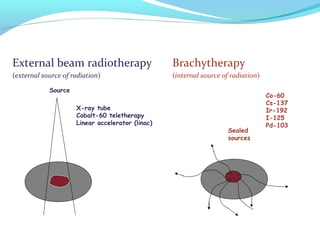
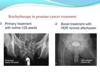
BRACHYTHERAPY
ADENEYE S.O.
DEPARTMENT OF RADIATION BIOLOGY AND
RADIOTHERAPY,
COLLEGE OF MEDICINE/ LAGOS
UNIVERSITY TEACHING HOSPITAL,
P. M. B. 12003, LAGOS.
E-Mail: asokjune@gmail.com, soadeneye@unilag.edu.ng
08035386915
INTRODUCTION
 Brachytherapy (also referred to as Curietherapy)
is defined as a short-distance treatment of malignant
disease with radiation emanating from small sealed
(encapsulated) sources.
 The sources are placed directly into the treatment
volume or near the treatment volume.
External beam radiotherapy Brachytherapy
(external source of radiation) (internal source of radiation)
Source
Sealed
sources
X-ray tube
Cobalt-60 teletherapy
Linear accelerator (linac)
Co-60
Cs-137
Ir-192
I-125
Pd-103
History
 Brachytherapy has been one of the earliest forms of
radiotherapy
 After discovery of radium by M Curie, radium was used for
brachytherapy already late 19th century
 There is a wide range of applications - this versatility has been
one of the most important features of brachytherapy
Brachytherapy compared to external beam therapy:
 Advantages of brachytherapy
Improved localized dose delivery to the target
Sharp dose fall-off outside the target volume
Better conformal therapy
 Disadvantages of brachytherapy
Only good for well localized tumors
Only good for small lesions
Very labor intensive
 Brachytherapy treatment outcome is affected by:
The particular model used for source distribution in the
target volume.
The algorithm used for calculation of dose distribution.
The methods used for the determination of the source
strength.
The dose rate and prescribed dose used in treatment.
Brachytherapy sources:
 Photon sources
Emit gamma rays through gamma decay and possibly
characteristic x rays through electron capture and internal
conversion
(examples: Co-60, Cs-137, Ir-192, I-125, Pd-103)
 Beta sources
Emit electrons following beta source decay
(example: Sr-90/Y-90)
 Neutron sources
Emit neutrons following spontaneous nuclear fission
(example: Cf-252)
Types of brachytherapy implants:
Intracavitary: Sources are placed into a body cavity.
Interstitial: Sources are implanted into the tumor volume.
Surface plaque: Sources are loaded into a plaque which is brought into
contact with a skin surface lesion.
Intraluminal: Sources are inserted into a lumen.
Intraoperative: Sources are brought surgically into or near the tumor.
volume.
Intravascular: Sources are brought intravascularly into a lesion or
near a lesion.
Brachytherapy classification with respect to treatment
duration:
Temporary implant
Dose is delivered over a period of time that is short in
comparison with the half-life of the sources.
Sources are removed when the prescribed dose has been
reached.
Permanent implant
Dose is delivered over the lifetime of the sources.
The sources undergo complete radioactive decay.
Brachytherapy classification with respect to source loading:
Hot loading
The applicator is pre-loaded and contains radioactive
sources at time of placement into the patient.
Afterloading
The applicator is placed first into the patient and the
radioactive sources are loaded later
- either by hand (manual afterloading)
- or by machine (automatic remote afterloading)
Manual afterloading
Generally, the radiation sources are
manually afterloaded into applicators or
catheters that have been placed within
the target volume. At the end of
treatment the sources are removed,
again manually.
The manual loading and removal of
sources from the applicators or
catheters result in some radiation
exposure to the medical and support
staff.
Remote afterloading
To minimize radiation exposure to medical and support
staff several computer driven remote afterloading
systems have been developed.
The use of remote afterloading machines offers several
practical advantages over manual procedures, such as:
Increased patient treatment capacity.
Consistent and reproducible treatment delivery.
Reduced radiation exposure to staff.
Remote afterloading
1970- 1990- 2000-
Cobalt RALSTON    Ir-192 RALS Cobalt RALS
Diameter 3 mm Diameter 1.1 mm Diameter 1.1 mm
  
Brachytherapy classification with respect to dose rate:
Low dose rate (LDR) (0.4 - 2 Gy/h)
Medium dose rate (MDR) (2 - 12 Gy/h)
High dose rate (HDR) ( > 12 Gy/h)
Brachytherapy classification with respect to dose rate:
In addition to LDR, MDR, and HDR brachytherapy
techniques, another type of afterloading brachytherapy
has been developed in which a continuous low dose rate
(LDR) treatment is simulated by a series of short
duration “dose pulses” of the order of 30 minutes
separated by intervals of 1 to several hours of no dose
given.
The technique is referred to as pulsed dose rate (PDR)
brachytherapy.
PHOTON SOURCE CHARACTERISTICS
Practical considerations
Brachytherapy sources are usually encapsulated and the
capsule serves multiple purposes:
 Contains the radioactivity
 Provides source rigidity
 Absorbs alpha and beta radiation produced through
source decay
 Dosimetric characteristics of brachytherapy sources:
 Photon energy
 Half-life
 Half-value layer in shielding materials
 Specific activity
 Source strength
 Inverse-square dose fall-off
 Photon energy of the brachytherapy source influences:
 Penetration into tissue
 Radiation protection requirements
 Tissue attenuation is very significant for low photon
energies of the order of 30 keV and below.
 Over a dozen radioactive nuclides have a history of
use as sealed sources in brachytherapy.
 The common contemporary sources are:
cobalt-60, cesium-137, iridium-192, iodine-125 and
paladium-103
 Less common sources are:
gold-198, ruthenium-106 and californium-252
 The use of radium-226 and radon-222 was
discontinued because of safety concerns.
Physical characteristics of brachytherapy sources
Characteristics of common radionuclides used in
brachytherapy
Nuclide Average Half-life HVL in lead
photon energy (mm)
(MeV)
Co-60 1.25 5.26 y 11 309 1.11
Cs-137 0.66 30 y 6.5 77.3 1.11
Au-198 0.41 2.7 d 2.5 56.2 1.13
Ir-192 0.38 73.8 d 3.0 108 1.12
I-125 0.028 60 d 0.02 - -
Pd-103 0.021 17 d 0.01 - -
ΓAKR
Λ
2
Gy m
GBq h
µ ×
 ÷
× 
-1
2 -1
cGy h
cGy cm h
 ×
 ÷
× × 
Mechanical characteristics of brachytherapy sources
 Brachytherapy photon sources are available in various
forms, such as:
 Needles (cesium-137)
 Tubes (cesium-137)
 Pellets (cobalt-60 and cesium-137)
 Seeds (iodine-125, paladium-103, iridium-192, gold-198)
 Wires (iridium-192)
Mechanical characteristics of brachytherapy sources
 The sources are used as sealed sources, usually doubly
encapsulated in order to:
 Provide adequate shielding against alpha and beta
radiation emitted from the source.
 Contain radioactive material.
 Prevent leakage of the radioactive material.
 Provide rigidity of the source.
Source specification
 Specification of gamma ray sources:
(1) Reference air kerma rate in air
(2) Air kerma strength SK
(3) Exposure rate in air
(4) Air kerma rate in air
&
air airref( ( ))K d
&
PX
&
air air( ( ))K d
Specification of gamma ray sources:
(1) Reference air kerma rate in air ,
defined by the ICRU (reports No. 38 and 58) as the air
kerma rate in air at a reference distance dref of 1 m,
corrected for air attenuation and scattering (unit: ).
The SI unit of the reference air kerma rate is Gy/s, but for
the purposes of source specification it is more convenient to
use for LDR sources and for HDR sources.
&
air airref( ( ))K d
1 µGy/h
µGy/h µGy/s
 Specification of gamma ray sources (cont.):
(2) Air kerma strength SK, defined by the AAPM as
The unit of air kerma strength is .
AAPM TG 43 recommends a shorthand notation with
U
= ×& 2
K air airref ref( ( ))S K d d
µ= × × = × ×2 -1 2 -1
1 U 1 Gy m h 1 cGy cm h
µ × ×2 -1
Gy m h
 Specification of gamma ray sources (cont.):
(3) Exposure rate in air at point P in air at a distance d
from the source:
where
A is the source activity in Ci
is the exposure rate constant in
d is the distance from the source in m
X
P 2
A
X
d
Γ
=&
&
PX
R⋅m2
⋅Ci-1
⋅h-1
ΓX
 Specification of gamma ray sources (cont.)
(4) Air kerma rate in air at point P in air at a
distance d from the source:
where
Aapp is the apparent activity of the source in Bq
is the air kerma rate constant given in
d is the distance from the source in m
&
air air( ( ))K d
app AKR
air air 2
( ( ))
A
K d
d
Γ
=&
µ × ×2
( Gy m )/ Bq h)(GΓAKR
 Specification of beta ray sources:
 The recommended quantity for the specification of
beta ray sources is the reference absorbed dose rate in
water at a reference distance from the source.
 The reference distance differs from one type of source
to another and is generally between 0.5 mm and 2 mm
from the source.
CLINICAL USE AND DOSIMETRY SYSTEMS
Gynaecology
 Intracavitary brachytherapy is mainly used for
treatment of the cancer of the cervix, uterine body and
vagina.
 Various applicators are in use to hold sources in an
appropriate configuration in the tumor volume.
 A cervical applicator consists of a central tube
(tandem) and lateral capsules (ovoids or colpostats).
 Female anatomy and placement of an applicator
(tandem and two ovoids) for treatment of the cancer
of the cervix with remote afterloading machine.
 AP and lateral radiographs of cervix treatment with an
applicator (tandem and two ovoids) loaded with a train
of “dummy cobalt-60 pellets”. The source train for
treatment is composed of active (0.5 Ci) and dummy
pellets to produce a train of 20 pellets for each of the
three channels.
Types of sources:
 The most widely used source for treatment of
gynaecological cancers is cesium-137. It is often
necessary to use sources of differing strengths in order
to achieve the desired dose distribution.
 In modern remote afterloading machines iridium-192
is the commonly used radionuclide.
Cancer of the uterus was first treated with radium in 1908.
Since then many systems have been designed for dose
delivery and specification.
The two most commonly used systems for dose
specification in treatment of the cervix are:
 The Manchester system
 The ICRU system
 The Manchester system is characterized by doses to
four points: point A, point B, bladder point, and
rectum point.
 The duration of the irradiation is based on the dose
rate at point A, which is located 2 cm superior to the
cervical orifice (os) and 2 cm lateral to the cervical
canal.
 Point B is defined 3 cm laterally to
point A when the central canal is not
displaced.
 Since point A relates to the position of the sources
rather than to a specific anatomic structure, it may lie
inside the tumour or outside the tumour.
 If the tandem displaces the central canal, point A
moves with the canal, but point B remains fixed at 5
cm from the midline.
 The gyneacological dosimetry system recommended
by the ICRU (Report 38) relates the dose distribution
to the target volume rather than to a specific point.
 The report identifies a dose level of 60 Gy as the
appropriate reference dose level for LDR treatments.
This results in a requirement to specify the
dimensions of the pear-shaped 60 Gy isodose
reference volume.
Gyneacological intracavitary applicators
 Vaginal applicators are used to irradiate tumours that
extend downward form the cervix along the vaginal
vault.
 The most commonly used applicator in the treatment
of cervical cancer is the Fletcher-Suit-Delcos system
consisting of a tandem and ovoids. The dose
distribution delivered by this rigid applicator system
can be optimized by a careful selection and placement
of the sources in the tandem and colpostats.
CLINICAL USE AND DOSIMETRY SYSTEM
Gynaecology
MANCHESTER
FLETCHER-SUIT
HENSCHKE
TANDEM-RING
TANDEM-RING
CT/MR
COMPATIBLE
Rectal and bladder dose monitoring
 The most frequent clinical complication of
intracavitary gyneacological radiation treatments
result from a high dose delivered to the portions of the
rectum and bladder.
 Applicators should be placed so as to keep the dose to
these critical structures as low as possible. Often
surgical gauze is used to displace the sensitive
structures away from the applicator.
Rectal and bladder dose monitoring
 Direct measurement of rectal and bladder dose has
been attempted using miniature ionization chambers,
scintillation detectors, and MOSFET dosimeters.
Measured data give large variability and correlate
poorly with calculated values.
 In order to keep the dose to critical structures (rectum
and bladder) as low as possible often surgical gauze is
used to displace the sensitive structures away from the
applicators.
Interstitial brachytherapy
In interstitial brachytherapy radioactive sources are
inserted directly into diseased tissue.
With regard to treatment time there are two types of
interstitial implants:
Temporary
Permanent
With regard to source loading there are three types of
interstitial implants:
Direct loading
Manual afterloading
Remote afterloading
The sources used in direct insertion are fabricated in the
form of needles, wires, or seeds.
The interstitial afterloading techniques consists of two
steps:
The first step consists of inserting unloaded, stainless-steel
needles (1-2 cm apart) into the tumour.
The second step consists of afterloading the unloaded
needles with radioactive seeds or connecting the needles to
an afterloading machine for remotely-controlled source
insertion.
Patient treated for carcinoma of the tongue with a HDR
remote control afterloading machine.
The HDR afterloading
machine uses an
iridium-192 source
and 18 catheters.
The typical initial source
activity is 3.7 1010
GBq
(10 Ci).
×
Patient treated for carcinoma of the lip with a HDR
remote control afterloading machine.
The HDR afterloading
machine uses an
iridium-192 source
and 18 catheters.
The typical initial source
activity is 3.7 1010
GBq
(10 Ci).
×
 Various pre-planning dosimetry systems have been
developed for clinical use, all based on tables of total
dose delivered as a function of area or volume to be
treated.
 The most commonly used systems are:
 Patterson-Parker (Manchester) system
 Quimby (Memorial) system
 Paris system
Patterson-Parker (Manchester) system
 The aim of this system is to deliver a uniform dose
(within of the prescribed dose) throughout the
target volume.
 The sources are distributed non-uniformly, following
certain rules, with more source strength concentrated
in the periphery of the target volume.
±10%
 The Patterson-Parker tables give cumulative source
strength required to deliver 900 cGy, using current
factors and units, as a function of:
 Area for planar implants
 Volume for volume implants
 If the sources are close to the patient surface one can
determine the size of the implant directly. If not, the
size is determined radiographically.
The Patterson-Parker tables
 Single plane: The source arrangement treats a 1 cm
thick slab of tissue. The prescribed dose is on a parallel
plane 0.5 cm away from the source plane.
 Double plane is used to treat slabs of tissue with
thickness between 1 cm and 2.5 cm. The required total
source strength is equally divided between the two
planes.
Quimby (Memorial) system
 The Quimby system is based on uniform distribution of
source strength, accepting a non-uniform delivery of
dose in the target volume, with the dose in the target
centre exceeding the dose on the periphery.
 The dose value obtained from the Quimby tables
represents the minimum dose within the target
volume.
Paris system
 The Paris system is used for single and double plane
implants.
 The general rules for the Paris system are as follows:
 Sources must be linear and their placement must be
parallel.
 Centres of all sources must be located in the same
(central) plane.
 Linear source strength (activity) must be uniform and
identical for all sources in the implant.
 Adjacent sources must be equidistant from one another.
Remote afterloading systems
 Remote afterloading machines are used in both
interstitial and intracavitary clinical applications.
 There are three distinct types of remote afterloading
device:
 LDR (low dose rate)
 HDR (high dose rate)
 PDR (pulsed dose rate).
 The essential components of remote afterloading
machines:
 A safe to house the radioactive source
 Radioactive sources (single or multiple)
 Remote operating console
 Source control and drive mechanism
 Source transfer guide tubes and treatment applicators
 Treatment planning computer
 The three common radionuclide sources used in remote
afterloading machines are: Co-60; Cs-137; Ir-192.
 Ir-192 is most widely used because of its medium gamma
ray energy and its high specific activity. Its
disadvantage is its relatively short half-life (73.8 d).
 LDR and HDR remote afterloading systems are used for
intracavitary, interstitial and intraluminal treatments.
:( 400 keV)
 The advantages of HDR machines are:
 Optimization of dose distribution
 Treatment on outpatient basis
 Elimination of staff radiation exposure
 The disadvantages of HDR systems are:
 Uncertainty in biological effectiveness
 Potential for accidental high exposures
 Potential for serious errors
 Increased staff commitment
Permanent prostate implants
 Brachytherapy is one of the treatment modalities for
early stage prostate cancer in which the disease is
confined to the prostate gland.
 The male pelvic anatomy:
The common modalities for treatment of prostate cancer
are:
 Surgery
 External beam radiotherapy
 Brachytherapy
Brachytherapy is applied in prostate treatment:
 As primary treatment using permanent implantation of
short lived radionuclide sources (such as I-125 or Pd-103)
emitting low energy photons .
 As a boost to external beam treatments delivered in the
form of fractionated or single session treatment using an
HDR machine.
(: 30 keV)
 Brachytherapy applied as primary treatment using
permanent implantation of short lived radionuclide
sources (such as I-125 or Pd-103) emitting low energy
photons.
 Prostate brachytherapy is reserved for treatment of
early stage cancer that has not spread outside the
prostate gland.
 Brachytherapy applied as a boost to external beam
treatments delivered in the form of fractionated or
single session treatment using an HDR machine.
Brachytherapy in prostate cancer treatment
 Primary treatment
with iodine-125 seeds
 Boost treatment with
HDR remote afterloader
Choice of radionuclide for prostate implant
 Introduction of low photon energy emitters iodine-125
and palladium-103 has renewed interest in permanent
prostate implants.
 Palladium-103, which has a shorter half-life (17 d) than
iodine-125 (60 d) delivers a higher initial dose rate and
is thus useful in treating fast growing high grade
tumours.
Seed implantation technique
There are two surgical approaches to performing
implantation of the prostate with radioactive seeds:
 Retropubic (open)
 Transperineal (closed)
The transperineal approach with ultrasound guidance has
become the technique of choice, in part because it is
carried out as an outpatient one day procedure.
Selection of patients for treatment with seed implants is
based on three parameters used to characterize prostate
tumours:
 Stage refers to size of tumour and its extension beyond
the prostate capsule. T1a is the smallest; T4 the largest
tumour.
 Grade is characterized by the Gleason score. Score 2
represents the most well behaved tumour; score 10 the
most aggressive tumour.
 PSA (prostate specific antigen) level represents the
quantity of cancer cells present and is usually placed
into one of four groups: 0 - 4; 4 - 10; 10 - 20; and greater
than 20.
Pre-planning, seed placement and dose distributions
 Pre-planning of the implant is based on either
ultrasound or CT cross-sectional (transverse, axial)
images.
 The intended treatment volume generally is the whole
prostate gland with a small margin of periprostatic
tissue. The seeds are placed and spaced so as to
minimize the dose to the urethra to decrease
complications.
 The number of seeds and their geometric placement in
the target volume is determined through optimized
computer dose planning or pre-calculated
Prescribed dose and post-treatment evaluation
 The recommended total dose to the periphery of the
target volume when brachytherapy implant is the sole
treatment modality is:
 150 - 160 Gy for iodine-125 seed implants
 115 - 120 Gy for palladium-103 seed implants
 Post-implant CT imaging:
 Is usually carried out two to three weeks post-
implantation to allow for seed migration and volume
reduction resulting from oedema.
 Dose calculations are performed and compared with
pre-implant dose distributions.
CLINICAL USE AND DOSIMETRY SYSTEMS
Eye plaques
 Intraocular melanoma is the most common primary
malignant eye tumour in adults, originating mostly in
the choroid (choroidal melanoma).
 Traditional treatment was
enucleation (surgical eye removal).
 More recent treatment approaches rely on radiotherapy:
 External beam radiotherapy with high energy x rays or
charged particles.
 Brachytherapy with temporary implants based on
radioactive seeds loaded onto an eye plaque.
Brachytherapy treatment
 Eye plaque loaded with radio-
active seeds is applied
externally to the scleral (outer)
eye surface over the tumour
base.
 Radiation with appropriate dose
is intended to eliminate tumour
cells without causing
anatomical or functional
damage to normal ocular
tissues.
Brachytherapy treatment with eye plaques
 Most commonly used seeds are iodine-125 seeds with
typical activities of the order of 1 mCi.
 The number of seeds per plaque ranges from 7 to 24
for plaque diameters of 12 to 20 mm.
 Typical treatment dose rates are of the order of 1 Gy/h
and typical prescription doses are of the order of 100
Gy.
Brachytherapy treatment with eye plaques
 Most commonly used seeds are iodine-125 seeds with
typical activities of the order of 1 mCi.
 A less common brachytherapy approach is based on
beta emitting sources, such as strontium-90/ittrium-
90 and, more recently, ruttenium-106
Intravascular brachytherapy
 Application of radiation (temporary or permanent
implant) after treatment of arterial stenosis with
angioplasty and stent placement has been proven
useful in preventing re-stenosis.
 Restenosis is the formation of scar tissue in an artery
within 6 months following angioplasty, occurring in
about 40% of angioplasty patients.
 The important characteristics of intravascular treatment
are:
 Type of source: electronic x ray, gamma ray, electron,
positron
 Physical form of radionuclide: wire, seed, pellet, metallic
stent
 Method of radiation delivery:
 Manual or remote afterloading;
 Syringe and inflatable balloon;
 Radioactive stent
 Radionuclide
 For use in afterloading: iridium-192; ittrium-90; strontium-
90/ittrium-90.
 For use in inflatable balloon: xenon-133; rhenium-186;
rhenium-188
 For use in radioactive stent: phosphorus-32; vanadium-48
DOSE SPECIFICATION AND REPORTING
Using standardized and uniform methodology, ICRU reports
38 and 58 recommend the minimum information that must
be reported when performing brachytherapy treatments,
such as:
 Description of the implant
 Definition of the volume of interest
 Prescription dose
 Delivered dose
 Reference air kerma rate in air in cGy/h at 1 m
Intracavitary treatments
The data recommended in the ICRU report 38 for reporting
of gynaecological brachytherapy are:
 Description of technique
 Reference air kerma rate in air in cGy/h at 1 m
 Time/dose pattern
 Description of the reference volume
 Dose at reference points (bladder, rectum, lymphatic
trapezoid, pelvic wall)
 Dimensions of the pear shaped 60 Gy isodose reference
volume
The data recommended in the ICRU report 58 for reporting
of interstitial implant treatments are:
 Description of the clinical target volume
 Sources, technique, and implant time
 Prescription dose
 Reference air kerma rate in air in cGy/h at 1 m
 Description of the dose distribution
 Description of the high and low dose region and dose
uniformity indices
 Dose-volume histograms
As far as dose distribution is concerned, four different dose
related quantities are to be reported to adequately describe
an implant treatment:
 Total reference air kerma
 Mean central dose representing the plateau dose region
inside the target volume
 Minimum dose, important for tumour control
 High dose regions exceeding 150% of the mean central
dose and low dose regions that are below 90% of the
peripheral dose.
DOSE CALCULATION PROCEDURE
Computerized treatment planning
Optimization of dose distribution
 In brachytherapy optimization of dose distribution is
usually achieved by establishing the relative spatial or
temporal distribution of the sources and by weighting
the strength of the individual sources.
 When computer algorithms are not available,
optimization is usually carried out by trial and
adjustment.
Optimization of dose distribution
 The current optimization approaches fall into one of
the following categories:
 Source distribution rules
 Geometry
 Specified dose points
 Trial and adjustment
Optimization of dose distributions (cont.)
 Optimization in HDR and PDR treatment planning for a
single stepping source involves manipulation of the
source dwell positions and the relative dwell times to
produce the desired dose distribution.
 Most current optimization methods are analytic. Other
approaches use random search techniques in which the
performance of the system is made to improve through
the use of an objective function.
DOSE CALCULATION PROCEDURES
Calculation of treatment time
 In calculating the total dose delivered during the
implant one must consider the exponential decay of the
source strength (activity).
 The cumulative dose Dcum delivered during time t is
initial dose rate
decay constant
half-life of the radioactive source
{ } 1/ 2
ln2
0
cum 0 1/ 2 0
0
1 1.44 1
tt
tt tD
D D e dt e t D eλ λ
λ
−
− −
  
= = − = − 
  
∫
&
& &
&
0D
λ
1/ 2t
For short treatment times compared to source half-life
 The cumulative dose is in general given by
 If the treatment time t is very short in comparison with
the half-life of the source, i.e., then
and
{ } 1/ 2
ln2
0
cum 0 1/ 2 0
0
1 1.44 1
tt
tt tD
D D e dt e t D eλ λ
λ
−
− −
  
= = − = − 
  
∫
&
& &
t1/2 t = t1/2
e
−
t ln2
t1/2
≈ 1−
t ln2
t1/2
cum 0D D t= &
DOSE CALCULATION PROCEDURES
Calculation of treatment time
Permanent implants
 The cumulative dose is in general given by
 For permanent implants and the following
relationship is used to determine the cumulative
dose to complete source decay
{ } 1/ 2
ln2
0
cum 0 1/ 2 0
0
1 1.44 1
tt
tt tD
D D e dt e t D eλ λ
λ
−
− −
  
= = − = − 
  
∫
&
& &
t = ∞
0
cum 1/ 2 01.44
D
D t D
λ
= =
&
&
COMMISSIONING OF BRACHYTHERAPY TPSs
Check of the reconstruction procedure
 The major hardware devices of brachytherapy
treatment planning systems (TPSs) are:
 Computer
 Digitizer
 Plotter
 The accuracy of the devices and the planning process
should be checked routinely with simple test cases for
a small number of sources placed in a known
geometry as seen on two orthogonal radiographs.
 The verification test should include translation from
film to Cartesian coordinates, rotations, and
corrections for magnification.
consistency between quantities and units
 The major sources of errors in brachytherapy are:
 Incorrect source calibration
 Incorrect use of dosimetric quantities and units in the
calculation algorithms.
 It is essential to verify correct labeling of the input and
output quantities and units used in the dose calculation
software.
 Special care must be taken with regard to the
specification of source strength (activity).
Computer vs. manual dose calculation
 The computer-calculated dose distribution around a
line source should be compared with:
 Published dose rate values for a similar source
 Sievert integral values obtained for the same source
 Additional tests should verify the validity of:
 The inverse square law for point sources
 Summation of the dose for multiple sources
 Scaling of the dose rate with source strength
 Scaling of the dose with time
Check of the decay corrections
 For temporary implants, the accuracy of the
computer- calculated dose rate at specific times within
the duration of the implant should be verified with
manual calculations.
 For permanent implants, the accuracy of the
computer-calculated dose to complete source decay
should be verified.
 For both types of implants (temporary and
permanent) the choice of units for the source strength,
dose rate, and total dose should be verified.
COMMISSIONING OF RADIOACTIVE SOURCES
Wipe tests
Shipment package
 A package containing shipment of a radionuclide must
be monitored immediately upon receipt for any
physical damage and excessive radiation levels.
 The package surface should be investigated with wipe
tests for any possible radioactive contamination.
 Radiation levels should be measured and recorded
both for the surface of the package and for several
points at a distance of 1 m from the package.
Individual encapsulated sources
 Individual encapsulated sources should be wipe-tested
for possible radioactive leakage and contamination.
 All new sources should be tested at time of receipt.
 Sources kept in permanent inventory should be tested
at intervals of 6 months.
 The measurement of contamination is usually carried
out with a sensitive scintillation well counter.
 A source is considered to be leaking if 200 Bq ( 5
nCi) of removable contamination is measured.
: :
Autoradiography and uniformity check of activity
 Radiography and autoradiography using a single film
exposure with a simulator can be used to check the
uniformity of activity.
 The developed film is scanned with a densitometer to
determine isodensity and isodose profiles.
 Autoradiographs are useful for checking a batch of
seeds or ribbons with seeds to establish:
 Uniformity of activity within each seed
 Presence of any inadvertent cold (non-radioactive)
seeds
Calibration chain
 Brachytherapy sources should have their source strength
calibration traceable to a national standards laboratory.
 In some instances it may be necessary to establish a
second level of traceability by comparison with a
calibrated source of the same type.
 Comparison calibrations are best done in well type (re-
entrant) ionization chambers which are suitable for
calibration of both high and low strength (activity)
sources.
Calibration chain
 The well type (re-entrant)
chambers must have a calibration
coefficient traceable to a standards
laboratory, i.e., they must have
been calibrated at a national
standards laboratory or at a
secondary standards laboratory.
 For high strength sources, the
source strength (activity)
measurements may also be carried
out with calibrated stem type
ionization chambers.
 Most standards laboratories will calibrate stem type
ionization chambers for different quality radiations,
and an interpolation or extrapolation method is then
used to obtain the calibration coefficient for a given
radionuclide source.
 The activity of all sources should be measured upon
receipt with a calibrated local dosimeter and the result
should be compared with manufacturer’s certificate of
source strength.
QUALITY ASSURANCE IN BRACHYTHERAPY
Constancy check of a calibrated dosimeter
 The constancy of the response of a calibrated
dosimetry system may be checked by periodic
response measurement with a long half-life source,
such as:
 Cesium-137 brachytherapy source for well-type (re-
entrant) ionization chambers.
 Cobalt-60 teletherapy machine in the case of a stem-
type ionization chamber.
 Commercial strontium-90/ittrium-90 calibration
source in the case of a stem-type ionization chamber
 The periodic constancy check measurement also
provides a good quality assurance check for the entire
measuring system.
 Appropriate calibration coefficients for the entire
dosimetric system must be obtained from a standards
laboratory on a regular basis, typically every two years.
Regular checks of sources and applicators
Mechanical properties
 The mechanical integrity of a source must be checked at
regular intervals by:
 Visual inspection
 Leak testing
 Activity measurement
 Visual inspection and radiographic evaluation of all
applicators should be carried out periodically.
Mechanical properties
 For gyneacological applicators it is necessary to check
that:
 The assembly is structurally sound.
 All clamps, screws and retaining devices are functioning
properly.
 Source insert carriers seat correctly in the colpostats.
Source strength (activity)
 Long half-life sources maintained within a permanent
inventory should be checked at reasonable frequency
for change with time in source strength (activity).
 Short half-life sources, used either for temporary or
permanent implants, should have their activity
measured at the time of receipt and the result should
be compared with the value stated on the
manufacturer’s certificate.
Source strength (activity)
 Any discrepancy between the locally-determined and
manufacturer’s stated value exceeding 10% should be
investigated and the patient should not be treated
until the discrepancy is explained and understood.
 The use of appropriate radiographic markers and
combination of a radiographic image with an
autoradiograph are convenient methods for checking
source positioning.
Radiation monitoring around patients
 After a permanent or temporary implantation of
radioactive sources in a patient, a radiation survey
must be carried out in areas within and around the
patient and the patient’s room.
 Radiation levels should be measured and recorded so
as to assist in maintaining minimum exposure to
hospital staff and visitors.
 The radiation levels in adjoining patients’ rooms
should be low so that no individual will be exposed to
an equivalent dose exceeding 0.2 mSv in any one hour.
 Prior to release of an implant patient from hospital the
patient and the patient’s room must be surveyed.
 For patients with temporary implants a survey must be
done upon removal of the sources to confirm complete
removal of all sources.
 Patients with permanent implants may be discharged
from the hospital if at the time of discharge the
radiation level at 1 m from the implant is less than 0.5
mSv/h.
 Patient discharged from the hospital with permanent
implants should be instructed to keep a distance from
children and pregnant women for a reasonable
amount of time after the implant.
Quality management programme
 All facilities performing brachytherapy procedures
should have in place some form of a quality
management programme.
 The objectives of the programme should be well
defined to ensure compliance with standard good
practices.
 The programme should include written procedures for
prescribing, recording and documenting each
treatment.
 The brachytherapy procedures manual should also
include written policies on reporting and recording
treatment errors.
The main objectives of a quality management programme
are:
 The preparation of a physician’s written directive
before administration of treatment.
 Clear identification of the patient.
 Documentation of treatment and related calculations.
 Compliance of each treatment with written directive.
 The identification and evaluation of any unintended
deviation from the prescription.

Brachytherapy msc lecture sam copy

  • 1.
    BRACHYTHERAPY ADENEYE S.O. DEPARTMENT OFRADIATION BIOLOGY AND RADIOTHERAPY, COLLEGE OF MEDICINE/ LAGOS UNIVERSITY TEACHING HOSPITAL, P. M. B. 12003, LAGOS. E-Mail: asokjune@gmail.com, soadeneye@unilag.edu.ng 08035386915
  • 2.
    INTRODUCTION  Brachytherapy (alsoreferred to as Curietherapy) is defined as a short-distance treatment of malignant disease with radiation emanating from small sealed (encapsulated) sources.  The sources are placed directly into the treatment volume or near the treatment volume.
  • 3.
    External beam radiotherapyBrachytherapy (external source of radiation) (internal source of radiation) Source Sealed sources X-ray tube Cobalt-60 teletherapy Linear accelerator (linac) Co-60 Cs-137 Ir-192 I-125 Pd-103
  • 4.
    History  Brachytherapy hasbeen one of the earliest forms of radiotherapy  After discovery of radium by M Curie, radium was used for brachytherapy already late 19th century  There is a wide range of applications - this versatility has been one of the most important features of brachytherapy
  • 5.
    Brachytherapy compared toexternal beam therapy:  Advantages of brachytherapy Improved localized dose delivery to the target Sharp dose fall-off outside the target volume Better conformal therapy  Disadvantages of brachytherapy Only good for well localized tumors Only good for small lesions Very labor intensive
  • 6.
     Brachytherapy treatmentoutcome is affected by: The particular model used for source distribution in the target volume. The algorithm used for calculation of dose distribution. The methods used for the determination of the source strength. The dose rate and prescribed dose used in treatment.
  • 7.
    Brachytherapy sources:  Photonsources Emit gamma rays through gamma decay and possibly characteristic x rays through electron capture and internal conversion (examples: Co-60, Cs-137, Ir-192, I-125, Pd-103)  Beta sources Emit electrons following beta source decay (example: Sr-90/Y-90)  Neutron sources Emit neutrons following spontaneous nuclear fission (example: Cf-252)
  • 8.
    Types of brachytherapyimplants: Intracavitary: Sources are placed into a body cavity. Interstitial: Sources are implanted into the tumor volume. Surface plaque: Sources are loaded into a plaque which is brought into contact with a skin surface lesion. Intraluminal: Sources are inserted into a lumen. Intraoperative: Sources are brought surgically into or near the tumor. volume. Intravascular: Sources are brought intravascularly into a lesion or near a lesion.
  • 9.
    Brachytherapy classification withrespect to treatment duration: Temporary implant Dose is delivered over a period of time that is short in comparison with the half-life of the sources. Sources are removed when the prescribed dose has been reached. Permanent implant Dose is delivered over the lifetime of the sources. The sources undergo complete radioactive decay.
  • 10.
    Brachytherapy classification withrespect to source loading: Hot loading The applicator is pre-loaded and contains radioactive sources at time of placement into the patient. Afterloading The applicator is placed first into the patient and the radioactive sources are loaded later - either by hand (manual afterloading) - or by machine (automatic remote afterloading)
  • 11.
    Manual afterloading Generally, theradiation sources are manually afterloaded into applicators or catheters that have been placed within the target volume. At the end of treatment the sources are removed, again manually. The manual loading and removal of sources from the applicators or catheters result in some radiation exposure to the medical and support staff.
  • 12.
    Remote afterloading To minimizeradiation exposure to medical and support staff several computer driven remote afterloading systems have been developed. The use of remote afterloading machines offers several practical advantages over manual procedures, such as: Increased patient treatment capacity. Consistent and reproducible treatment delivery. Reduced radiation exposure to staff.
  • 13.
    Remote afterloading 1970- 1990-2000- Cobalt RALSTON    Ir-192 RALS Cobalt RALS Diameter 3 mm Diameter 1.1 mm Diameter 1.1 mm   
  • 14.
    Brachytherapy classification withrespect to dose rate: Low dose rate (LDR) (0.4 - 2 Gy/h) Medium dose rate (MDR) (2 - 12 Gy/h) High dose rate (HDR) ( > 12 Gy/h)
  • 15.
    Brachytherapy classification withrespect to dose rate: In addition to LDR, MDR, and HDR brachytherapy techniques, another type of afterloading brachytherapy has been developed in which a continuous low dose rate (LDR) treatment is simulated by a series of short duration “dose pulses” of the order of 30 minutes separated by intervals of 1 to several hours of no dose given. The technique is referred to as pulsed dose rate (PDR) brachytherapy.
  • 16.
    PHOTON SOURCE CHARACTERISTICS Practicalconsiderations Brachytherapy sources are usually encapsulated and the capsule serves multiple purposes:  Contains the radioactivity  Provides source rigidity  Absorbs alpha and beta radiation produced through source decay
  • 17.
     Dosimetric characteristicsof brachytherapy sources:  Photon energy  Half-life  Half-value layer in shielding materials  Specific activity  Source strength  Inverse-square dose fall-off
  • 18.
     Photon energyof the brachytherapy source influences:  Penetration into tissue  Radiation protection requirements  Tissue attenuation is very significant for low photon energies of the order of 30 keV and below.
  • 19.
     Over adozen radioactive nuclides have a history of use as sealed sources in brachytherapy.  The common contemporary sources are: cobalt-60, cesium-137, iridium-192, iodine-125 and paladium-103  Less common sources are: gold-198, ruthenium-106 and californium-252  The use of radium-226 and radon-222 was discontinued because of safety concerns.
  • 20.
    Physical characteristics ofbrachytherapy sources Characteristics of common radionuclides used in brachytherapy Nuclide Average Half-life HVL in lead photon energy (mm) (MeV) Co-60 1.25 5.26 y 11 309 1.11 Cs-137 0.66 30 y 6.5 77.3 1.11 Au-198 0.41 2.7 d 2.5 56.2 1.13 Ir-192 0.38 73.8 d 3.0 108 1.12 I-125 0.028 60 d 0.02 - - Pd-103 0.021 17 d 0.01 - - ΓAKR Λ 2 Gy m GBq h µ ×  ÷ ×  -1 2 -1 cGy h cGy cm h  ×  ÷ × × 
  • 21.
    Mechanical characteristics ofbrachytherapy sources  Brachytherapy photon sources are available in various forms, such as:  Needles (cesium-137)  Tubes (cesium-137)  Pellets (cobalt-60 and cesium-137)  Seeds (iodine-125, paladium-103, iridium-192, gold-198)  Wires (iridium-192)
  • 22.
    Mechanical characteristics ofbrachytherapy sources  The sources are used as sealed sources, usually doubly encapsulated in order to:  Provide adequate shielding against alpha and beta radiation emitted from the source.  Contain radioactive material.  Prevent leakage of the radioactive material.  Provide rigidity of the source.
  • 23.
    Source specification  Specificationof gamma ray sources: (1) Reference air kerma rate in air (2) Air kerma strength SK (3) Exposure rate in air (4) Air kerma rate in air & air airref( ( ))K d & PX & air air( ( ))K d
  • 24.
    Specification of gammaray sources: (1) Reference air kerma rate in air , defined by the ICRU (reports No. 38 and 58) as the air kerma rate in air at a reference distance dref of 1 m, corrected for air attenuation and scattering (unit: ). The SI unit of the reference air kerma rate is Gy/s, but for the purposes of source specification it is more convenient to use for LDR sources and for HDR sources. & air airref( ( ))K d 1 µGy/h µGy/h µGy/s
  • 25.
     Specification ofgamma ray sources (cont.): (2) Air kerma strength SK, defined by the AAPM as The unit of air kerma strength is . AAPM TG 43 recommends a shorthand notation with U = ×& 2 K air airref ref( ( ))S K d d µ= × × = × ×2 -1 2 -1 1 U 1 Gy m h 1 cGy cm h µ × ×2 -1 Gy m h
  • 26.
     Specification ofgamma ray sources (cont.): (3) Exposure rate in air at point P in air at a distance d from the source: where A is the source activity in Ci is the exposure rate constant in d is the distance from the source in m X P 2 A X d Γ =& & PX R⋅m2 ⋅Ci-1 ⋅h-1 ΓX
  • 27.
     Specification ofgamma ray sources (cont.) (4) Air kerma rate in air at point P in air at a distance d from the source: where Aapp is the apparent activity of the source in Bq is the air kerma rate constant given in d is the distance from the source in m & air air( ( ))K d app AKR air air 2 ( ( )) A K d d Γ =& µ × ×2 ( Gy m )/ Bq h)(GΓAKR
  • 28.
     Specification ofbeta ray sources:  The recommended quantity for the specification of beta ray sources is the reference absorbed dose rate in water at a reference distance from the source.  The reference distance differs from one type of source to another and is generally between 0.5 mm and 2 mm from the source.
  • 29.
    CLINICAL USE ANDDOSIMETRY SYSTEMS Gynaecology  Intracavitary brachytherapy is mainly used for treatment of the cancer of the cervix, uterine body and vagina.  Various applicators are in use to hold sources in an appropriate configuration in the tumor volume.  A cervical applicator consists of a central tube (tandem) and lateral capsules (ovoids or colpostats).
  • 30.
     Female anatomyand placement of an applicator (tandem and two ovoids) for treatment of the cancer of the cervix with remote afterloading machine.
  • 31.
     AP andlateral radiographs of cervix treatment with an applicator (tandem and two ovoids) loaded with a train of “dummy cobalt-60 pellets”. The source train for treatment is composed of active (0.5 Ci) and dummy pellets to produce a train of 20 pellets for each of the three channels.
  • 32.
    Types of sources: The most widely used source for treatment of gynaecological cancers is cesium-137. It is often necessary to use sources of differing strengths in order to achieve the desired dose distribution.  In modern remote afterloading machines iridium-192 is the commonly used radionuclide.
  • 33.
    Cancer of theuterus was first treated with radium in 1908. Since then many systems have been designed for dose delivery and specification. The two most commonly used systems for dose specification in treatment of the cervix are:  The Manchester system  The ICRU system
  • 34.
     The Manchestersystem is characterized by doses to four points: point A, point B, bladder point, and rectum point.  The duration of the irradiation is based on the dose rate at point A, which is located 2 cm superior to the cervical orifice (os) and 2 cm lateral to the cervical canal.  Point B is defined 3 cm laterally to point A when the central canal is not displaced.
  • 35.
     Since pointA relates to the position of the sources rather than to a specific anatomic structure, it may lie inside the tumour or outside the tumour.  If the tandem displaces the central canal, point A moves with the canal, but point B remains fixed at 5 cm from the midline.
  • 36.
     The gyneacologicaldosimetry system recommended by the ICRU (Report 38) relates the dose distribution to the target volume rather than to a specific point.  The report identifies a dose level of 60 Gy as the appropriate reference dose level for LDR treatments. This results in a requirement to specify the dimensions of the pear-shaped 60 Gy isodose reference volume.
  • 37.
    Gyneacological intracavitary applicators Vaginal applicators are used to irradiate tumours that extend downward form the cervix along the vaginal vault.  The most commonly used applicator in the treatment of cervical cancer is the Fletcher-Suit-Delcos system consisting of a tandem and ovoids. The dose distribution delivered by this rigid applicator system can be optimized by a careful selection and placement of the sources in the tandem and colpostats.
  • 38.
    CLINICAL USE ANDDOSIMETRY SYSTEM Gynaecology MANCHESTER FLETCHER-SUIT HENSCHKE TANDEM-RING TANDEM-RING CT/MR COMPATIBLE
  • 39.
    Rectal and bladderdose monitoring  The most frequent clinical complication of intracavitary gyneacological radiation treatments result from a high dose delivered to the portions of the rectum and bladder.  Applicators should be placed so as to keep the dose to these critical structures as low as possible. Often surgical gauze is used to displace the sensitive structures away from the applicator.
  • 40.
    Rectal and bladderdose monitoring  Direct measurement of rectal and bladder dose has been attempted using miniature ionization chambers, scintillation detectors, and MOSFET dosimeters. Measured data give large variability and correlate poorly with calculated values.  In order to keep the dose to critical structures (rectum and bladder) as low as possible often surgical gauze is used to displace the sensitive structures away from the applicators.
  • 41.
    Interstitial brachytherapy In interstitialbrachytherapy radioactive sources are inserted directly into diseased tissue. With regard to treatment time there are two types of interstitial implants: Temporary Permanent With regard to source loading there are three types of interstitial implants: Direct loading Manual afterloading Remote afterloading
  • 42.
    The sources usedin direct insertion are fabricated in the form of needles, wires, or seeds. The interstitial afterloading techniques consists of two steps: The first step consists of inserting unloaded, stainless-steel needles (1-2 cm apart) into the tumour. The second step consists of afterloading the unloaded needles with radioactive seeds or connecting the needles to an afterloading machine for remotely-controlled source insertion.
  • 43.
    Patient treated forcarcinoma of the tongue with a HDR remote control afterloading machine. The HDR afterloading machine uses an iridium-192 source and 18 catheters. The typical initial source activity is 3.7 1010 GBq (10 Ci). ×
  • 44.
    Patient treated forcarcinoma of the lip with a HDR remote control afterloading machine. The HDR afterloading machine uses an iridium-192 source and 18 catheters. The typical initial source activity is 3.7 1010 GBq (10 Ci). ×
  • 45.
     Various pre-planningdosimetry systems have been developed for clinical use, all based on tables of total dose delivered as a function of area or volume to be treated.  The most commonly used systems are:  Patterson-Parker (Manchester) system  Quimby (Memorial) system  Paris system
  • 46.
    Patterson-Parker (Manchester) system The aim of this system is to deliver a uniform dose (within of the prescribed dose) throughout the target volume.  The sources are distributed non-uniformly, following certain rules, with more source strength concentrated in the periphery of the target volume. ±10%
  • 47.
     The Patterson-Parkertables give cumulative source strength required to deliver 900 cGy, using current factors and units, as a function of:  Area for planar implants  Volume for volume implants  If the sources are close to the patient surface one can determine the size of the implant directly. If not, the size is determined radiographically.
  • 48.
    The Patterson-Parker tables Single plane: The source arrangement treats a 1 cm thick slab of tissue. The prescribed dose is on a parallel plane 0.5 cm away from the source plane.  Double plane is used to treat slabs of tissue with thickness between 1 cm and 2.5 cm. The required total source strength is equally divided between the two planes.
  • 49.
    Quimby (Memorial) system The Quimby system is based on uniform distribution of source strength, accepting a non-uniform delivery of dose in the target volume, with the dose in the target centre exceeding the dose on the periphery.  The dose value obtained from the Quimby tables represents the minimum dose within the target volume.
  • 50.
    Paris system  TheParis system is used for single and double plane implants.  The general rules for the Paris system are as follows:  Sources must be linear and their placement must be parallel.  Centres of all sources must be located in the same (central) plane.  Linear source strength (activity) must be uniform and identical for all sources in the implant.  Adjacent sources must be equidistant from one another.
  • 51.
    Remote afterloading systems Remote afterloading machines are used in both interstitial and intracavitary clinical applications.  There are three distinct types of remote afterloading device:  LDR (low dose rate)  HDR (high dose rate)  PDR (pulsed dose rate).
  • 52.
     The essentialcomponents of remote afterloading machines:  A safe to house the radioactive source  Radioactive sources (single or multiple)  Remote operating console  Source control and drive mechanism  Source transfer guide tubes and treatment applicators  Treatment planning computer
  • 53.
     The threecommon radionuclide sources used in remote afterloading machines are: Co-60; Cs-137; Ir-192.  Ir-192 is most widely used because of its medium gamma ray energy and its high specific activity. Its disadvantage is its relatively short half-life (73.8 d).  LDR and HDR remote afterloading systems are used for intracavitary, interstitial and intraluminal treatments. :( 400 keV)
  • 54.
     The advantagesof HDR machines are:  Optimization of dose distribution  Treatment on outpatient basis  Elimination of staff radiation exposure  The disadvantages of HDR systems are:  Uncertainty in biological effectiveness  Potential for accidental high exposures  Potential for serious errors  Increased staff commitment
  • 55.
    Permanent prostate implants Brachytherapy is one of the treatment modalities for early stage prostate cancer in which the disease is confined to the prostate gland.  The male pelvic anatomy:
  • 56.
    The common modalitiesfor treatment of prostate cancer are:  Surgery  External beam radiotherapy  Brachytherapy Brachytherapy is applied in prostate treatment:  As primary treatment using permanent implantation of short lived radionuclide sources (such as I-125 or Pd-103) emitting low energy photons .  As a boost to external beam treatments delivered in the form of fractionated or single session treatment using an HDR machine. (: 30 keV)
  • 57.
     Brachytherapy appliedas primary treatment using permanent implantation of short lived radionuclide sources (such as I-125 or Pd-103) emitting low energy photons.  Prostate brachytherapy is reserved for treatment of early stage cancer that has not spread outside the prostate gland.
  • 58.
     Brachytherapy appliedas a boost to external beam treatments delivered in the form of fractionated or single session treatment using an HDR machine.
  • 59.
    Brachytherapy in prostatecancer treatment  Primary treatment with iodine-125 seeds  Boost treatment with HDR remote afterloader
  • 60.
    Choice of radionuclidefor prostate implant  Introduction of low photon energy emitters iodine-125 and palladium-103 has renewed interest in permanent prostate implants.  Palladium-103, which has a shorter half-life (17 d) than iodine-125 (60 d) delivers a higher initial dose rate and is thus useful in treating fast growing high grade tumours.
  • 61.
    Seed implantation technique Thereare two surgical approaches to performing implantation of the prostate with radioactive seeds:  Retropubic (open)  Transperineal (closed) The transperineal approach with ultrasound guidance has become the technique of choice, in part because it is carried out as an outpatient one day procedure.
  • 62.
    Selection of patientsfor treatment with seed implants is based on three parameters used to characterize prostate tumours:  Stage refers to size of tumour and its extension beyond the prostate capsule. T1a is the smallest; T4 the largest tumour.  Grade is characterized by the Gleason score. Score 2 represents the most well behaved tumour; score 10 the most aggressive tumour.  PSA (prostate specific antigen) level represents the quantity of cancer cells present and is usually placed into one of four groups: 0 - 4; 4 - 10; 10 - 20; and greater than 20.
  • 63.
    Pre-planning, seed placementand dose distributions  Pre-planning of the implant is based on either ultrasound or CT cross-sectional (transverse, axial) images.  The intended treatment volume generally is the whole prostate gland with a small margin of periprostatic tissue. The seeds are placed and spaced so as to minimize the dose to the urethra to decrease complications.  The number of seeds and their geometric placement in the target volume is determined through optimized computer dose planning or pre-calculated
  • 64.
    Prescribed dose andpost-treatment evaluation  The recommended total dose to the periphery of the target volume when brachytherapy implant is the sole treatment modality is:  150 - 160 Gy for iodine-125 seed implants  115 - 120 Gy for palladium-103 seed implants  Post-implant CT imaging:  Is usually carried out two to three weeks post- implantation to allow for seed migration and volume reduction resulting from oedema.  Dose calculations are performed and compared with pre-implant dose distributions.
  • 65.
    CLINICAL USE ANDDOSIMETRY SYSTEMS Eye plaques  Intraocular melanoma is the most common primary malignant eye tumour in adults, originating mostly in the choroid (choroidal melanoma).  Traditional treatment was enucleation (surgical eye removal).  More recent treatment approaches rely on radiotherapy:  External beam radiotherapy with high energy x rays or charged particles.  Brachytherapy with temporary implants based on radioactive seeds loaded onto an eye plaque.
  • 66.
    Brachytherapy treatment  Eyeplaque loaded with radio- active seeds is applied externally to the scleral (outer) eye surface over the tumour base.  Radiation with appropriate dose is intended to eliminate tumour cells without causing anatomical or functional damage to normal ocular tissues.
  • 67.
    Brachytherapy treatment witheye plaques  Most commonly used seeds are iodine-125 seeds with typical activities of the order of 1 mCi.  The number of seeds per plaque ranges from 7 to 24 for plaque diameters of 12 to 20 mm.  Typical treatment dose rates are of the order of 1 Gy/h and typical prescription doses are of the order of 100 Gy.
  • 68.
    Brachytherapy treatment witheye plaques  Most commonly used seeds are iodine-125 seeds with typical activities of the order of 1 mCi.  A less common brachytherapy approach is based on beta emitting sources, such as strontium-90/ittrium- 90 and, more recently, ruttenium-106
  • 69.
    Intravascular brachytherapy  Applicationof radiation (temporary or permanent implant) after treatment of arterial stenosis with angioplasty and stent placement has been proven useful in preventing re-stenosis.  Restenosis is the formation of scar tissue in an artery within 6 months following angioplasty, occurring in about 40% of angioplasty patients.
  • 70.
     The importantcharacteristics of intravascular treatment are:  Type of source: electronic x ray, gamma ray, electron, positron  Physical form of radionuclide: wire, seed, pellet, metallic stent  Method of radiation delivery:  Manual or remote afterloading;  Syringe and inflatable balloon;  Radioactive stent  Radionuclide  For use in afterloading: iridium-192; ittrium-90; strontium- 90/ittrium-90.  For use in inflatable balloon: xenon-133; rhenium-186; rhenium-188  For use in radioactive stent: phosphorus-32; vanadium-48
  • 71.
    DOSE SPECIFICATION ANDREPORTING Using standardized and uniform methodology, ICRU reports 38 and 58 recommend the minimum information that must be reported when performing brachytherapy treatments, such as:  Description of the implant  Definition of the volume of interest  Prescription dose  Delivered dose  Reference air kerma rate in air in cGy/h at 1 m
  • 72.
    Intracavitary treatments The datarecommended in the ICRU report 38 for reporting of gynaecological brachytherapy are:  Description of technique  Reference air kerma rate in air in cGy/h at 1 m  Time/dose pattern  Description of the reference volume  Dose at reference points (bladder, rectum, lymphatic trapezoid, pelvic wall)  Dimensions of the pear shaped 60 Gy isodose reference volume
  • 73.
    The data recommendedin the ICRU report 58 for reporting of interstitial implant treatments are:  Description of the clinical target volume  Sources, technique, and implant time  Prescription dose  Reference air kerma rate in air in cGy/h at 1 m  Description of the dose distribution  Description of the high and low dose region and dose uniformity indices  Dose-volume histograms
  • 74.
    As far asdose distribution is concerned, four different dose related quantities are to be reported to adequately describe an implant treatment:  Total reference air kerma  Mean central dose representing the plateau dose region inside the target volume  Minimum dose, important for tumour control  High dose regions exceeding 150% of the mean central dose and low dose regions that are below 90% of the peripheral dose.
  • 75.
    DOSE CALCULATION PROCEDURE Computerizedtreatment planning Optimization of dose distribution  In brachytherapy optimization of dose distribution is usually achieved by establishing the relative spatial or temporal distribution of the sources and by weighting the strength of the individual sources.  When computer algorithms are not available, optimization is usually carried out by trial and adjustment.
  • 76.
    Optimization of dosedistribution  The current optimization approaches fall into one of the following categories:  Source distribution rules  Geometry  Specified dose points  Trial and adjustment
  • 77.
    Optimization of dosedistributions (cont.)  Optimization in HDR and PDR treatment planning for a single stepping source involves manipulation of the source dwell positions and the relative dwell times to produce the desired dose distribution.  Most current optimization methods are analytic. Other approaches use random search techniques in which the performance of the system is made to improve through the use of an objective function.
  • 78.
    DOSE CALCULATION PROCEDURES Calculationof treatment time  In calculating the total dose delivered during the implant one must consider the exponential decay of the source strength (activity).  The cumulative dose Dcum delivered during time t is initial dose rate decay constant half-life of the radioactive source { } 1/ 2 ln2 0 cum 0 1/ 2 0 0 1 1.44 1 tt tt tD D D e dt e t D eλ λ λ − − −    = = − = −     ∫ & & & & 0D λ 1/ 2t
  • 79.
    For short treatmenttimes compared to source half-life  The cumulative dose is in general given by  If the treatment time t is very short in comparison with the half-life of the source, i.e., then and { } 1/ 2 ln2 0 cum 0 1/ 2 0 0 1 1.44 1 tt tt tD D D e dt e t D eλ λ λ − − −    = = − = −     ∫ & & & t1/2 t = t1/2 e − t ln2 t1/2 ≈ 1− t ln2 t1/2 cum 0D D t= &
  • 80.
    DOSE CALCULATION PROCEDURES Calculationof treatment time Permanent implants  The cumulative dose is in general given by  For permanent implants and the following relationship is used to determine the cumulative dose to complete source decay { } 1/ 2 ln2 0 cum 0 1/ 2 0 0 1 1.44 1 tt tt tD D D e dt e t D eλ λ λ − − −    = = − = −     ∫ & & & t = ∞ 0 cum 1/ 2 01.44 D D t D λ = = & &
  • 81.
    COMMISSIONING OF BRACHYTHERAPYTPSs Check of the reconstruction procedure  The major hardware devices of brachytherapy treatment planning systems (TPSs) are:  Computer  Digitizer  Plotter  The accuracy of the devices and the planning process should be checked routinely with simple test cases for a small number of sources placed in a known geometry as seen on two orthogonal radiographs.  The verification test should include translation from film to Cartesian coordinates, rotations, and corrections for magnification.
  • 82.
    consistency between quantitiesand units  The major sources of errors in brachytherapy are:  Incorrect source calibration  Incorrect use of dosimetric quantities and units in the calculation algorithms.  It is essential to verify correct labeling of the input and output quantities and units used in the dose calculation software.  Special care must be taken with regard to the specification of source strength (activity).
  • 83.
    Computer vs. manualdose calculation  The computer-calculated dose distribution around a line source should be compared with:  Published dose rate values for a similar source  Sievert integral values obtained for the same source  Additional tests should verify the validity of:  The inverse square law for point sources  Summation of the dose for multiple sources  Scaling of the dose rate with source strength  Scaling of the dose with time
  • 84.
    Check of thedecay corrections  For temporary implants, the accuracy of the computer- calculated dose rate at specific times within the duration of the implant should be verified with manual calculations.  For permanent implants, the accuracy of the computer-calculated dose to complete source decay should be verified.  For both types of implants (temporary and permanent) the choice of units for the source strength, dose rate, and total dose should be verified.
  • 85.
    COMMISSIONING OF RADIOACTIVESOURCES Wipe tests Shipment package  A package containing shipment of a radionuclide must be monitored immediately upon receipt for any physical damage and excessive radiation levels.  The package surface should be investigated with wipe tests for any possible radioactive contamination.  Radiation levels should be measured and recorded both for the surface of the package and for several points at a distance of 1 m from the package.
  • 86.
    Individual encapsulated sources Individual encapsulated sources should be wipe-tested for possible radioactive leakage and contamination.  All new sources should be tested at time of receipt.  Sources kept in permanent inventory should be tested at intervals of 6 months.  The measurement of contamination is usually carried out with a sensitive scintillation well counter.  A source is considered to be leaking if 200 Bq ( 5 nCi) of removable contamination is measured. : :
  • 87.
    Autoradiography and uniformitycheck of activity  Radiography and autoradiography using a single film exposure with a simulator can be used to check the uniformity of activity.  The developed film is scanned with a densitometer to determine isodensity and isodose profiles.  Autoradiographs are useful for checking a batch of seeds or ribbons with seeds to establish:  Uniformity of activity within each seed  Presence of any inadvertent cold (non-radioactive) seeds
  • 88.
    Calibration chain  Brachytherapysources should have their source strength calibration traceable to a national standards laboratory.  In some instances it may be necessary to establish a second level of traceability by comparison with a calibrated source of the same type.  Comparison calibrations are best done in well type (re- entrant) ionization chambers which are suitable for calibration of both high and low strength (activity) sources.
  • 89.
    Calibration chain  Thewell type (re-entrant) chambers must have a calibration coefficient traceable to a standards laboratory, i.e., they must have been calibrated at a national standards laboratory or at a secondary standards laboratory.  For high strength sources, the source strength (activity) measurements may also be carried out with calibrated stem type ionization chambers.
  • 90.
     Most standardslaboratories will calibrate stem type ionization chambers for different quality radiations, and an interpolation or extrapolation method is then used to obtain the calibration coefficient for a given radionuclide source.  The activity of all sources should be measured upon receipt with a calibrated local dosimeter and the result should be compared with manufacturer’s certificate of source strength.
  • 91.
    QUALITY ASSURANCE INBRACHYTHERAPY Constancy check of a calibrated dosimeter  The constancy of the response of a calibrated dosimetry system may be checked by periodic response measurement with a long half-life source, such as:  Cesium-137 brachytherapy source for well-type (re- entrant) ionization chambers.  Cobalt-60 teletherapy machine in the case of a stem- type ionization chamber.  Commercial strontium-90/ittrium-90 calibration source in the case of a stem-type ionization chamber
  • 92.
     The periodicconstancy check measurement also provides a good quality assurance check for the entire measuring system.  Appropriate calibration coefficients for the entire dosimetric system must be obtained from a standards laboratory on a regular basis, typically every two years.
  • 93.
    Regular checks ofsources and applicators Mechanical properties  The mechanical integrity of a source must be checked at regular intervals by:  Visual inspection  Leak testing  Activity measurement  Visual inspection and radiographic evaluation of all applicators should be carried out periodically.
  • 94.
    Mechanical properties  Forgyneacological applicators it is necessary to check that:  The assembly is structurally sound.  All clamps, screws and retaining devices are functioning properly.  Source insert carriers seat correctly in the colpostats.
  • 95.
    Source strength (activity) Long half-life sources maintained within a permanent inventory should be checked at reasonable frequency for change with time in source strength (activity).  Short half-life sources, used either for temporary or permanent implants, should have their activity measured at the time of receipt and the result should be compared with the value stated on the manufacturer’s certificate.
  • 96.
    Source strength (activity) Any discrepancy between the locally-determined and manufacturer’s stated value exceeding 10% should be investigated and the patient should not be treated until the discrepancy is explained and understood.
  • 97.
     The useof appropriate radiographic markers and combination of a radiographic image with an autoradiograph are convenient methods for checking source positioning.
  • 98.
    Radiation monitoring aroundpatients  After a permanent or temporary implantation of radioactive sources in a patient, a radiation survey must be carried out in areas within and around the patient and the patient’s room.  Radiation levels should be measured and recorded so as to assist in maintaining minimum exposure to hospital staff and visitors.
  • 99.
     The radiationlevels in adjoining patients’ rooms should be low so that no individual will be exposed to an equivalent dose exceeding 0.2 mSv in any one hour.  Prior to release of an implant patient from hospital the patient and the patient’s room must be surveyed.  For patients with temporary implants a survey must be done upon removal of the sources to confirm complete removal of all sources.
  • 100.
     Patients withpermanent implants may be discharged from the hospital if at the time of discharge the radiation level at 1 m from the implant is less than 0.5 mSv/h.  Patient discharged from the hospital with permanent implants should be instructed to keep a distance from children and pregnant women for a reasonable amount of time after the implant.
  • 101.
    Quality management programme All facilities performing brachytherapy procedures should have in place some form of a quality management programme.  The objectives of the programme should be well defined to ensure compliance with standard good practices.  The programme should include written procedures for prescribing, recording and documenting each treatment.  The brachytherapy procedures manual should also include written policies on reporting and recording treatment errors.
  • 102.
    The main objectivesof a quality management programme are:  The preparation of a physician’s written directive before administration of treatment.  Clear identification of the patient.  Documentation of treatment and related calculations.  Compliance of each treatment with written directive.  The identification and evaluation of any unintended deviation from the prescription.