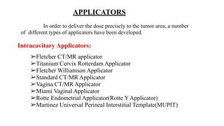
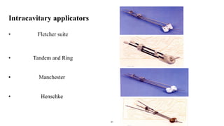
HDR BRACHYTHERAPY
PRESENTED BY
KRISHAN MURARI
RADIATION THERAPIST
BRACHYTHERAPY
➢ It is a method of treatment in which sealed radioactive source
are used to deliver radiation at short distance to the tumor.
➢ The radioactive source placed inside or near the body surface,
within natural body cavities or implanted directly into the tumor.
Classification of brachytherapy:
Based on loading
Based on removal of sources
Based on implant technique
Based on dose rate
➢ Pre-loading(Hot Loading)
➢ Manual after-loading
➢ Remote after-loading
Intracavitary
Interstitial
Mould
Intraluminal
Intraoperative
Temporary Implant
Permanent Implant
Low Dose Rate(LDR)
Medium Dose Rate(MDR)
High Dose Rate(HDR)
Pulsed Dose Rate(PDR)
Source Loading
Pre-loading(HOT Loading):The applicator is preloaded and contains
radioactive sources at the time of placement into the patient.
Manual after-loading: The applicator is placed first into the target position and
the radioactive sources are loaded later by hand.
Disadvantage:
Exposure to medical and support staff.
4
Remote after-loading: The applicator is placed first into
the target position and the radioactive sources are loaded
later by a machine
Advantage:
➢ Increased patient treatment capacity.
➢ Consistent and reproducible treatment delivery.
➢ Reduced radiation exposure to staff.
Duration of treatment
Temporary Implant : Dose is delivered over a short period of time
and the sources are removed after the prescribed dose has been
reached.
Examples: Cesium-137, Iridium-192, Cobalt-60
Permanent Implant: Dose is delivered over the lifetime of the
source until complete decay)
Example: Gold-198,Iodine-125
6
Implant technique types
Intracavitary : Sources are placed into body cavities close to the tumour volume
Interstitial: Sources are implanted surgically within the tumour volume
Surface Mould: Sources are placed over the Skin/tissue to be treated
Intraluminal : Sources are placed in a lumen
Intraoperative: Sources are implanted into the target tissue during surgery
Intravascular: A single source is placed into small or large arteries
7
8
Intracavitary Interstitial
Surface Mould
Intraluminal
Intra Operative
Implant technique types
Intravascular
Dose Rate Classification
• Low Dose Rate : < 2 Gy/hour
• Medium Dose Rate : 2-12 Gy/hour
• High Dose Rate : >12 Gy/hour
• Pulsed Dose Rate : pulses of around 1 Gy/hour.
9
High Dose Rate(HDR) Brachytherapy
➢ It has dose rate more than 12 Gy per hour.
➢ It used with remote afterloader in well shielded rooms.
➢ Very high activity sources are used and produce very intense
radiation field.
➢ Advantage
A specified dose can be delivered in minutes, instead of days
Patients are not required to remain in the hospital.
➢ Examples
Iridium-192, Cobalt-60
Desirable Properties
➢ Source may be naturally available or artificially obtained
➢Long Half life is required for permanent storage
➢ Charged Particle emission should be absent
➢Should not be gaseous disintegration product
➢should have high specific activity
➢Possible to available in different shapes, sizes
➢should be insoluble, nontoxic and not in powder form
HDR Brachytherapy Source
Sources used in Brachytherapy
• Radium -226:
• First source used in Brachytherapy.
• It is a naturally available source.
• It decays to Pb-206 by emitting 0.83MeV (Average) energy.
• Disadvantage:
• Daughter product , RADON is an alpha emitter.
• It is a Gas which is soluble in tissue.
• It can escape through hairline crack in the radium capsule.
• low specific activity ( 0.98 Ci/g).
• Radiation production for these source wants to required large thickness.
Cesium 137:
Cs- 137 is a nuclear fission by product and decays to Ba -137 by emitting
0.662MeV gamma energy.
Disadvantage:
Its low specific activity (50Ci/g)
limited this usage in LDR only.
Cobalt – 60:
➢ Co-60 is a neutron activated product, which decays to Ni-60 by emitting
1.25MeV (Average) energy.
➢ High specific activity (200 Ci/g) makes its wide usage in Brachy earlier.
But due to short half life (5.26Y) and cost effective, no longer used at
present in Brachy.
Disadvantage:
➢ Higher cost
➢ Higher Energy (1.25MeV)
➢ Required Higher shielding.
Iridium -192:
➢ It is more popular as a replacement of Ra-226.
➢ It decays to Pt-192 by emitting 0.361MeV (Average) energy.
Advantage:
➢ High Specific activity ( 400 Ci/g)
➢ Higher Energy (0.3MeV)
➢ Disadvantage:
➢ short half life (73.8 days)
Iridium-192 HDR Sources
16
Ideal characteristics of HDR equipment:
(i) A shielding safe to store the source when not in use.
(ii) A system to move the source from the safe to the treatment position.
This includes a driving mechanism, a channel position control and a
timer control system.
(iii) Emergency systems that allow the source to be withdrawn into the
safe if something goes wrong. Such a system must include a manual
retraction mechanism.
(iv) A console to program the treatment and to control the different steps
of the operation of the equipment.
HDR-Units
Microselectron
(ELEKTA)
Gammamed plus IX
(VARIAN)
Multisource
Bravos
Varian 30CH
Varisource 20 CH
MACHINE COMPONENTS:
1. Treatment Unit Head
2. Treatment Unit Base
3. Telescopic Mounting
4. Source storage (safe)
5. Indexer Locking System
6. Access Panel to access Head Cranks
7. Safe and Radiation Indicators: emergency
Button
8. Head Up/Down switch
9. Cable Hook
10.Brakes
11.Mains Switch with indicator light
12.Mains Fuses
13.Mains Cable
14.System cable to connection Box (via
Junction Box to TCP)
Treatment Unit Head:
Indexer:
➢ The main function of the indexer is the channel
selection.
➢ The indexer has locking system due to safety
purpose.
➢ The indexer locking ring is designed to secure
applicators into position when inserted in the
indexer. This is done by turning the locking ring
slightly clockwise.
Indexer motor:
➢ It is used to source is running desired channel.
➢ Movie the source to indexer through a cable.
Function:
➢ Channel selection
➢ Applicator detection
Stepper Motor:
➢Stepper motor is consisting of gearwheel and shaft
encoder.
➢There are two motor is there on machine head. Each
motor has 5 coils.
➢This motor is connected to cranks.
➢It is mainly perform the source movement work.
Emergency Stop Button on Head:
➢Machine head have one main emergency stop button
on Head. It is useful for during source stuck.
➢After pressing this emergency stop button the main
power supply of machine is cut and two 12-volt
battery inside the machine is retract the source into
safe position.
Emergency Hand Crank:
➢ During the source stuck in case of emergency button
is not working then manually rotate the golden crank
to retract the source into safe position.
Scintillation Type Integrated Radiation
Detector:
➢ Radiation is detected although the source should be in
the safe.
➢ Radiation level is low, although the source should be
outside of the safe.
Head Movement Switch (Up/Down):
➢ This switch is used to increase or decrease the height
of the machine head based on treatment position.
Power controller circuit board:
Control power supply to the complete machine.
It is distribute the power supply from main connection
into different part of machine such as
1. Indexer Motor
2. Telescope Motor
3. Backup Battery
Backup battery:
➢ There are two 12-volt
Battery is present at
both side of the
machine.
➢ Suppose main power
supply produce any
interrupts from power
this two 12 volt supply
are manage to power of
the whole machine.
➢ Safety features of Remote Afterloader:
➢ HDR remote afterloader are complicated device containing very high
activity radioactive source. Because of high dose rate and the short
treatment time, it may be accident can happen quickly.
➢ All these units have many safety features and operational interlocks
to prevent the accident. There are flowing by,
➢Emergency Switch
➢Emergency Crank
➢Door Interlock
➢Audio/Visual System
➢Radiation Monitor
➢Treatment ON Indicator.
➢Backup Battery
TREATMENT CONTROL PANEL COMPONENTS (TCP):
➢ Start Button
➢ Interrupt
➢ Emergency key
➢ Reset Key
➢ Service Key
Emergency/Service Container:
➢ The emergency/Service container
can be used for temporarily
keeping the source, either in the
emergency well or in the service
channel.
➢ The emergency/Service container
cannot be considered as a storage
container.
➢ The source is in this container
access in the treatment room is
restricted due to insufficient
shielding of Container:
Intracavitary Applicators:
➢Fletcher CT/MR applicator
➢Titanium Cervix Rotterdam Applicator
➢Fletcher Williamson Applicator
➢Standard CT/MR Applicator
➢Vagina CT/MR Applicator
➢Miami Vaginal Applicator
➢Rotte Endometrial Applicator(Rotte Y Applicator)
➢Martinez Universal Perineal Interstitial Template(MUPIT)
In order to deliver the dose precisely to the tumor area, a number
of different types of applicators have been developed.
APPLICATORS
Manchester Applicator
Tandem of variable length and angles
Ovoids of di
ff
erent sizes and shapes
31
Intracavitary applicators
• Fletcher suite
• Tandem and Ring
• Manchester
• Henschke
Intraluminal Applicator
• The Standard Nasopharyngeal Applicator
• Easophagal Applicator
• Lumencath Applicator
Interstitial Applicator:
• Pipard Template set
• Kuske Breast Applicator
• Martinez Brachytherapy Prostate Template
Surface Applicator:
• Leipzig Applicator
• Freiburg Flap Applicator
Dose Specification
• Most commonly used systems of dose specification for Intracavitary treatments are
Machester System and ICRU System
• Manchester System is characterized by dose to points A and B, Bladder and Rectum
• In ICRU system, apart from dose to points A and B, dose to target volume is
recommended. 60Gy isodose surface is chosen as the reference volume.
• Reference points recommended for dose to organs at risk.
• Dose to bony structures specified (nodal points in the pelvic region).
• Reporting of Total Reference Air Kerma
ICRU 38 Treatment Reporting
•Description of the technique used
•Total reference air kerma (cGy@ 1m)
•Absorbed dose at reference point
•Bladder
•Rectum
•Lymphatic trapezoid
•Pelvic wall reference point
•Reference volume
•Shape (pear) and dimensions
Point A and Isodose Shape
• Point A was first introduced in the Manchester dosimetric system
•Not recommended by ICRU 38
• The isodose line is pear shaped (dotted line)
ICRU 38- Dose ,Volume and Reporting Intracavitary
Brachytherapy in Gynecology.
Point A is defined as a point 2 cm
lateral to the central canal of the uterus
and 2cm superior to external cervical OS
Point B is defined as being in the
transverse axis through points A, 5 cm
from the midline.
Applicator Points:
Dose distribution in brachytherapy for
cervix cancer
Combination of intrauterine source
and intravaginal sources results in frontal pear
safe isodose surface used to extend dose
distributions laterally and in sagittal banana
shape isodose surfaces used to spare rectum
and bladder in the AP direction.
Bladder reference point:
On the lateral radiograph, the
bladder reference point is obtained on an
AP line drawn through the centre of the
balloon. The reference point is taken on
this line at the posterior surface of the
balloon.
Rectum reference point:
On the lateral radiograph, an anterior-
posterior line is drawn from the lower end of
the intrauterine source (or from the middle of
the intra vaginal sources). The point is located
on this line, 5 mm behind the posterior vaginal
wall (not in the contrast filling tube).
The lymphatic trapezoid: on the left on the AP radiograph,
and on the right on the lateral.
lymphatic trapezoid of fletcher
The points correspond to the paraaortic and
iliac nodes
Pelvic wall points
On the lateral view these points are marked as
the highest middistance points of the right and left
acetabulums.
Time dose fraction
the duration and time sequence of the implant
relative to the external beam treatment should be
recorded.
Interstitial Brachytherapy
• Various preplanning dosimetry systems have been developed for Interstitial
therapy
• In early years Tables of total dose as a function of area or volume were made
use of
• Two systems widely used were P-P (Manchester) and Quimby (Memorial
system)
• In P-P System uniform dose (±10%) by non uniform distribution of activity
• In Quimby System uniform distribution of activity resulting non uniform dose
Interstitial Therapy-Contd
• A more recent system is Paris System
• Primarily for single plane and multi-planar implants
• Sources must be linear and parallel
• Centre of all sources in the same plane
• Linear source strength must be uniform
• Adjacent sources must be equidistant
• Spacing between sources wider for long sources
Stockholm system
• Course over a period of 1 month.
• Time interval each fraction is 24 hrs
• This system is used by, intravaginal box made up of silver or
gold
• Intrauterine made up of flexible rubbers
• Unequal loading of radium
• 32 to 90 mg radium was placed inside the uterus
• 60 to 80 mg placed the vagina
• Total dose of 6500 to 7000 mg/hr
• Dose rate- 110 R/hr
Paris system
• Single fraction of radium 120 hrs (5 to 6 days)
• This system is used by two cork colpostats (cylinder)
• Intrauterine tube made up of silk rubber
• Equal amount of radium used uterus and vagina
• Total dose 7000 to 8000 mg/hr
• Dose rate 45R/hr
Manchester system
• Fractionated (2 to 3 fraction)
• Course over a period of 1 month
• Time interval each fraction 72 hrs
• Applicator- tandem and ovoids ect.
• Point A,B was introduced it was easily adopted by different
afterloading techniques
Computer aided systems Brachytherapy treatment planning
software
●Varian BrachyVision
●Varian VariSeed(for prostate implant)
●Philips Medical Systems Pinnacle
●CMS Interplant(for prostate implant)
●NucletronPLATO Brachytherapy/Oncentra
●Prowess Panther 3D BrachyPro
●Rosses Medical Systems Strata Suite
Treatment planning
• Planning software
• Catheter reconstructions
• Activation
• Dose normalization
• Dose optimization
• Geometric optimization
• Dose point optimization
• Graphical optimization
• Inverse optimazation
• Dose prescription
• Dose calculation
Orthogonal X ray image
with isodose curves
Short comings
• In complex implants having
many sources, any individual
source may be hidden in one or
both of the two films.
• Sources may be hidden by
anatomical structure or by other
sources.
Difference between 2D& 3D planning
2D planning 3D planning
Total dose Use physical dos Use biologically weighted dose
Dose prescription Point A Target volume
Volumes Only describe tumor volumes
Tumor and OAR volumes
CTV split into HR CTV,IR
CTV,LR CTV
Reference volumes 60 Gy isodose volume 60Gy 80Gy isodose volume
Dose optimization
Based on dose points, isodose
shape
Based on dose points, isodose
shape and coverage, DVH
Dose reporting
Point A, bladder, rectum, shape
ref isodose.
Same as in 2D + other volumes
Advantages of brachytherapy
•Less exposure for radiation workers
•Dose optimization
•Outpatient treatment
•Better documentation
•Use of Calibrated Sources
•Accurate positioning of sources
•Use of suitable dosimetric model for treatment time and dose calculations
•Additional advantage of gynecological treatments
•Less movement of the applicator
•Dose reduction to normal tissue
•Applicator size
Disadvantage
•High cost
•Complexity
•Compressed time frame
•Labor intensive
•As the dose rate increases the radio sensitivity
increases for both normal tissue and tumors
BRACHYTHERAPY OVERVIEW  AND  APPLICATORS

BRACHYTHERAPY OVERVIEW AND APPLICATORS

  • 1.
    HDR BRACHYTHERAPY PRESENTED BY KRISHANMURARI RADIATION THERAPIST
  • 2.
    BRACHYTHERAPY ➢ It isa method of treatment in which sealed radioactive source are used to deliver radiation at short distance to the tumor. ➢ The radioactive source placed inside or near the body surface, within natural body cavities or implanted directly into the tumor.
  • 3.
    Classification of brachytherapy: Basedon loading Based on removal of sources Based on implant technique Based on dose rate ➢ Pre-loading(Hot Loading) ➢ Manual after-loading ➢ Remote after-loading Intracavitary Interstitial Mould Intraluminal Intraoperative Temporary Implant Permanent Implant Low Dose Rate(LDR) Medium Dose Rate(MDR) High Dose Rate(HDR) Pulsed Dose Rate(PDR)
  • 4.
    Source Loading Pre-loading(HOT Loading):Theapplicator is preloaded and contains radioactive sources at the time of placement into the patient. Manual after-loading: The applicator is placed first into the target position and the radioactive sources are loaded later by hand. Disadvantage: Exposure to medical and support staff. 4
  • 5.
    Remote after-loading: Theapplicator is placed first into the target position and the radioactive sources are loaded later by a machine Advantage: ➢ Increased patient treatment capacity. ➢ Consistent and reproducible treatment delivery. ➢ Reduced radiation exposure to staff.
  • 6.
    Duration of treatment TemporaryImplant : Dose is delivered over a short period of time and the sources are removed after the prescribed dose has been reached. Examples: Cesium-137, Iridium-192, Cobalt-60 Permanent Implant: Dose is delivered over the lifetime of the source until complete decay) Example: Gold-198,Iodine-125 6
  • 7.
    Implant technique types Intracavitary: Sources are placed into body cavities close to the tumour volume Interstitial: Sources are implanted surgically within the tumour volume Surface Mould: Sources are placed over the Skin/tissue to be treated Intraluminal : Sources are placed in a lumen Intraoperative: Sources are implanted into the target tissue during surgery Intravascular: A single source is placed into small or large arteries 7
  • 8.
    8 Intracavitary Interstitial Surface Mould Intraluminal IntraOperative Implant technique types Intravascular
  • 9.
    Dose Rate Classification •Low Dose Rate : < 2 Gy/hour • Medium Dose Rate : 2-12 Gy/hour • High Dose Rate : >12 Gy/hour • Pulsed Dose Rate : pulses of around 1 Gy/hour. 9
  • 10.
    High Dose Rate(HDR)Brachytherapy ➢ It has dose rate more than 12 Gy per hour. ➢ It used with remote afterloader in well shielded rooms. ➢ Very high activity sources are used and produce very intense radiation field. ➢ Advantage A specified dose can be delivered in minutes, instead of days Patients are not required to remain in the hospital. ➢ Examples Iridium-192, Cobalt-60
  • 11.
    Desirable Properties ➢ Sourcemay be naturally available or artificially obtained ➢Long Half life is required for permanent storage ➢ Charged Particle emission should be absent ➢Should not be gaseous disintegration product ➢should have high specific activity ➢Possible to available in different shapes, sizes ➢should be insoluble, nontoxic and not in powder form HDR Brachytherapy Source
  • 12.
    Sources used inBrachytherapy • Radium -226: • First source used in Brachytherapy. • It is a naturally available source. • It decays to Pb-206 by emitting 0.83MeV (Average) energy. • Disadvantage: • Daughter product , RADON is an alpha emitter. • It is a Gas which is soluble in tissue. • It can escape through hairline crack in the radium capsule. • low specific activity ( 0.98 Ci/g). • Radiation production for these source wants to required large thickness.
  • 13.
    Cesium 137: Cs- 137is a nuclear fission by product and decays to Ba -137 by emitting 0.662MeV gamma energy. Disadvantage: Its low specific activity (50Ci/g) limited this usage in LDR only.
  • 14.
    Cobalt – 60: ➢Co-60 is a neutron activated product, which decays to Ni-60 by emitting 1.25MeV (Average) energy. ➢ High specific activity (200 Ci/g) makes its wide usage in Brachy earlier. But due to short half life (5.26Y) and cost effective, no longer used at present in Brachy. Disadvantage: ➢ Higher cost ➢ Higher Energy (1.25MeV) ➢ Required Higher shielding.
  • 15.
    Iridium -192: ➢ Itis more popular as a replacement of Ra-226. ➢ It decays to Pt-192 by emitting 0.361MeV (Average) energy. Advantage: ➢ High Specific activity ( 400 Ci/g) ➢ Higher Energy (0.3MeV) ➢ Disadvantage: ➢ short half life (73.8 days)
  • 16.
  • 17.
    Ideal characteristics ofHDR equipment: (i) A shielding safe to store the source when not in use. (ii) A system to move the source from the safe to the treatment position. This includes a driving mechanism, a channel position control and a timer control system. (iii) Emergency systems that allow the source to be withdrawn into the safe if something goes wrong. Such a system must include a manual retraction mechanism. (iv) A console to program the treatment and to control the different steps of the operation of the equipment.
  • 18.
  • 19.
    MACHINE COMPONENTS: 1. TreatmentUnit Head 2. Treatment Unit Base 3. Telescopic Mounting 4. Source storage (safe) 5. Indexer Locking System 6. Access Panel to access Head Cranks 7. Safe and Radiation Indicators: emergency Button 8. Head Up/Down switch 9. Cable Hook 10.Brakes 11.Mains Switch with indicator light 12.Mains Fuses 13.Mains Cable 14.System cable to connection Box (via Junction Box to TCP)
  • 20.
  • 21.
    Indexer: ➢ The mainfunction of the indexer is the channel selection. ➢ The indexer has locking system due to safety purpose. ➢ The indexer locking ring is designed to secure applicators into position when inserted in the indexer. This is done by turning the locking ring slightly clockwise. Indexer motor: ➢ It is used to source is running desired channel. ➢ Movie the source to indexer through a cable. Function: ➢ Channel selection ➢ Applicator detection
  • 22.
    Stepper Motor: ➢Stepper motoris consisting of gearwheel and shaft encoder. ➢There are two motor is there on machine head. Each motor has 5 coils. ➢This motor is connected to cranks. ➢It is mainly perform the source movement work. Emergency Stop Button on Head: ➢Machine head have one main emergency stop button on Head. It is useful for during source stuck. ➢After pressing this emergency stop button the main power supply of machine is cut and two 12-volt battery inside the machine is retract the source into safe position.
  • 23.
    Emergency Hand Crank: ➢During the source stuck in case of emergency button is not working then manually rotate the golden crank to retract the source into safe position. Scintillation Type Integrated Radiation Detector: ➢ Radiation is detected although the source should be in the safe. ➢ Radiation level is low, although the source should be outside of the safe.
  • 24.
    Head Movement Switch(Up/Down): ➢ This switch is used to increase or decrease the height of the machine head based on treatment position. Power controller circuit board: Control power supply to the complete machine. It is distribute the power supply from main connection into different part of machine such as 1. Indexer Motor 2. Telescope Motor 3. Backup Battery
  • 25.
    Backup battery: ➢ Thereare two 12-volt Battery is present at both side of the machine. ➢ Suppose main power supply produce any interrupts from power this two 12 volt supply are manage to power of the whole machine.
  • 26.
    ➢ Safety featuresof Remote Afterloader: ➢ HDR remote afterloader are complicated device containing very high activity radioactive source. Because of high dose rate and the short treatment time, it may be accident can happen quickly. ➢ All these units have many safety features and operational interlocks to prevent the accident. There are flowing by, ➢Emergency Switch ➢Emergency Crank ➢Door Interlock ➢Audio/Visual System ➢Radiation Monitor ➢Treatment ON Indicator. ➢Backup Battery
  • 27.
    TREATMENT CONTROL PANELCOMPONENTS (TCP): ➢ Start Button ➢ Interrupt ➢ Emergency key ➢ Reset Key ➢ Service Key
  • 28.
    Emergency/Service Container: ➢ Theemergency/Service container can be used for temporarily keeping the source, either in the emergency well or in the service channel. ➢ The emergency/Service container cannot be considered as a storage container. ➢ The source is in this container access in the treatment room is restricted due to insufficient shielding of Container:
  • 29.
    Intracavitary Applicators: ➢Fletcher CT/MRapplicator ➢Titanium Cervix Rotterdam Applicator ➢Fletcher Williamson Applicator ➢Standard CT/MR Applicator ➢Vagina CT/MR Applicator ➢Miami Vaginal Applicator ➢Rotte Endometrial Applicator(Rotte Y Applicator) ➢Martinez Universal Perineal Interstitial Template(MUPIT) In order to deliver the dose precisely to the tumor area, a number of different types of applicators have been developed. APPLICATORS
  • 30.
    Manchester Applicator Tandem ofvariable length and angles Ovoids of di ff erent sizes and shapes
  • 31.
    31 Intracavitary applicators • Fletchersuite • Tandem and Ring • Manchester • Henschke
  • 33.
    Intraluminal Applicator • TheStandard Nasopharyngeal Applicator • Easophagal Applicator • Lumencath Applicator Interstitial Applicator: • Pipard Template set • Kuske Breast Applicator • Martinez Brachytherapy Prostate Template Surface Applicator: • Leipzig Applicator • Freiburg Flap Applicator
  • 34.
    Dose Specification • Mostcommonly used systems of dose specification for Intracavitary treatments are Machester System and ICRU System • Manchester System is characterized by dose to points A and B, Bladder and Rectum • In ICRU system, apart from dose to points A and B, dose to target volume is recommended. 60Gy isodose surface is chosen as the reference volume. • Reference points recommended for dose to organs at risk. • Dose to bony structures specified (nodal points in the pelvic region). • Reporting of Total Reference Air Kerma
  • 35.
    ICRU 38 TreatmentReporting •Description of the technique used •Total reference air kerma (cGy@ 1m) •Absorbed dose at reference point •Bladder •Rectum •Lymphatic trapezoid •Pelvic wall reference point •Reference volume •Shape (pear) and dimensions
  • 36.
    Point A andIsodose Shape • Point A was first introduced in the Manchester dosimetric system •Not recommended by ICRU 38 • The isodose line is pear shaped (dotted line)
  • 37.
    ICRU 38- Dose,Volume and Reporting Intracavitary Brachytherapy in Gynecology. Point A is defined as a point 2 cm lateral to the central canal of the uterus and 2cm superior to external cervical OS Point B is defined as being in the transverse axis through points A, 5 cm from the midline. Applicator Points:
  • 38.
    Dose distribution inbrachytherapy for cervix cancer Combination of intrauterine source and intravaginal sources results in frontal pear safe isodose surface used to extend dose distributions laterally and in sagittal banana shape isodose surfaces used to spare rectum and bladder in the AP direction.
  • 39.
    Bladder reference point: Onthe lateral radiograph, the bladder reference point is obtained on an AP line drawn through the centre of the balloon. The reference point is taken on this line at the posterior surface of the balloon. Rectum reference point: On the lateral radiograph, an anterior- posterior line is drawn from the lower end of the intrauterine source (or from the middle of the intra vaginal sources). The point is located on this line, 5 mm behind the posterior vaginal wall (not in the contrast filling tube).
  • 40.
    The lymphatic trapezoid:on the left on the AP radiograph, and on the right on the lateral. lymphatic trapezoid of fletcher The points correspond to the paraaortic and iliac nodes Pelvic wall points On the lateral view these points are marked as the highest middistance points of the right and left acetabulums. Time dose fraction the duration and time sequence of the implant relative to the external beam treatment should be recorded.
  • 41.
    Interstitial Brachytherapy • Variouspreplanning dosimetry systems have been developed for Interstitial therapy • In early years Tables of total dose as a function of area or volume were made use of • Two systems widely used were P-P (Manchester) and Quimby (Memorial system) • In P-P System uniform dose (±10%) by non uniform distribution of activity • In Quimby System uniform distribution of activity resulting non uniform dose
  • 42.
    Interstitial Therapy-Contd • Amore recent system is Paris System • Primarily for single plane and multi-planar implants • Sources must be linear and parallel • Centre of all sources in the same plane • Linear source strength must be uniform • Adjacent sources must be equidistant • Spacing between sources wider for long sources
  • 43.
    Stockholm system • Courseover a period of 1 month. • Time interval each fraction is 24 hrs • This system is used by, intravaginal box made up of silver or gold • Intrauterine made up of flexible rubbers • Unequal loading of radium • 32 to 90 mg radium was placed inside the uterus • 60 to 80 mg placed the vagina • Total dose of 6500 to 7000 mg/hr • Dose rate- 110 R/hr
  • 44.
    Paris system • Singlefraction of radium 120 hrs (5 to 6 days) • This system is used by two cork colpostats (cylinder) • Intrauterine tube made up of silk rubber • Equal amount of radium used uterus and vagina • Total dose 7000 to 8000 mg/hr • Dose rate 45R/hr
  • 45.
    Manchester system • Fractionated(2 to 3 fraction) • Course over a period of 1 month • Time interval each fraction 72 hrs • Applicator- tandem and ovoids ect. • Point A,B was introduced it was easily adopted by different afterloading techniques
  • 46.
    Computer aided systemsBrachytherapy treatment planning software ●Varian BrachyVision ●Varian VariSeed(for prostate implant) ●Philips Medical Systems Pinnacle ●CMS Interplant(for prostate implant) ●NucletronPLATO Brachytherapy/Oncentra ●Prowess Panther 3D BrachyPro ●Rosses Medical Systems Strata Suite
  • 47.
    Treatment planning • Planningsoftware • Catheter reconstructions • Activation • Dose normalization • Dose optimization • Geometric optimization • Dose point optimization • Graphical optimization • Inverse optimazation • Dose prescription • Dose calculation
  • 48.
    Orthogonal X rayimage with isodose curves Short comings • In complex implants having many sources, any individual source may be hidden in one or both of the two films. • Sources may be hidden by anatomical structure or by other sources.
  • 49.
    Difference between 2D&3D planning 2D planning 3D planning Total dose Use physical dos Use biologically weighted dose Dose prescription Point A Target volume Volumes Only describe tumor volumes Tumor and OAR volumes CTV split into HR CTV,IR CTV,LR CTV Reference volumes 60 Gy isodose volume 60Gy 80Gy isodose volume Dose optimization Based on dose points, isodose shape Based on dose points, isodose shape and coverage, DVH Dose reporting Point A, bladder, rectum, shape ref isodose. Same as in 2D + other volumes
  • 50.
    Advantages of brachytherapy •Lessexposure for radiation workers •Dose optimization •Outpatient treatment •Better documentation •Use of Calibrated Sources •Accurate positioning of sources •Use of suitable dosimetric model for treatment time and dose calculations •Additional advantage of gynecological treatments •Less movement of the applicator •Dose reduction to normal tissue •Applicator size
  • 51.
    Disadvantage •High cost •Complexity •Compressed timeframe •Labor intensive •As the dose rate increases the radio sensitivity increases for both normal tissue and tumors