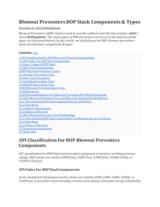
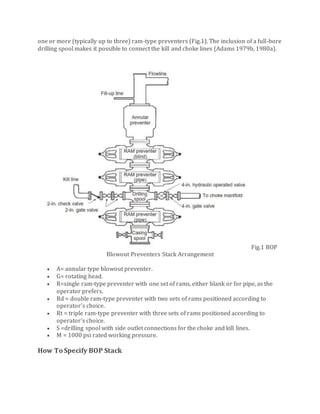
Simple Explanation about BOP stack or blowout preventers and it explians more its classifications, API codes and arrangements. You will find also ENI recommendation for BOP operations
Blowout preventers are critical well control equipment used to seal the wellbore. They consist of valves attached to the wellhead that can seal around drill pipes or close the wellbore entirely. The document discusses the types of blowout preventers, criteria for selection, specifications including sizes and pressure ratings, components like ram and annular blowout preventers, and testing procedures to ensure proper operation. Function tests are performed weekly to verify components can close and seal within specified time limits using stored accumulator pressure.
This document provides an overview of well control techniques. It discusses the importance of maintaining primary well control by keeping hydrostatic pressure greater than formation pressure. It describes what a kick is and types of kicks that can occur. Common causes of kicks include not keeping the hole full, insufficient mud density, swabbing, lost circulation, and poor well planning. Warning signs of a kick and methods for recognition are outlined. Finally, it discusses the objective of well control and some important well control concepts like determining reservoir pressure and selecting a well control method.
This document discusses drilling optimization by considering drilling problems and their solutions. It begins by describing different types of stuck pipe situations including bridging, pack off, wellbore geometry issues, and differential sticking. It then examines indicators and prevention methods for several specific causes of stuck pipe like unconsolidated formations, cement blocks, junk, key seating, ledges, undergauge holes, and mobile formations like salt. The document also reviews rate of penetration factors, well control methods, kick causes, and provides a case study example for calculating differential force, buoyant weight, hook load, and margin of overpull to free a stuck pipe.
This document discusses well intervention using coiled tubing. It defines coiled tubing and its main components, which include an injector head, coiled tubing reel, control unit, power pack unit, and bottom-hole assembly. Coiled tubing can be used for various applications like wellbore cleanout, milling, logging, perforating, drilling deviated wells, fluid conveyance, and tool conveyance. It has advantages over conventional drilling like not requiring connections and allowing faster tripping in and out. However, coiled tubing also has disadvantages like fatigue life limits and reduced bore diameter.
This document provides an introduction to well control from Kingdom Drilling Services. It discusses primary and secondary well control, including maintaining pressure and monitoring flows. Loss of primary control can occur through pressure changes or lost circulation. Secondary control indicators include increased flow rates or mud pit volume changes. Methods for controlling kicks include circulating or bullheading. The document also covers well control terms, blowout prevention, shallow well hazards, and lost circulation detection and remedies.
The document discusses various drilling problems that can occur such as pipe sticking, loss of circulation, hole deviation, and more. It describes the causes and solutions for different types of pipe sticking problems including differential pressure sticking and mechanical sticking due to cuttings accumulation, borehole instability, or key seating. The document also covers loss of circulation issues and explains common lost circulation zones and causes. Planning and understanding potential problems is key to successfully reaching the target zone.
This document discusses downhole problems that can occur while drilling wells and methods to prevent them. It covers various downhole problems like pipe sticking, pipe failure, dog legs, key seats, shale problems, and lost circulation. Pipe sticking can be mechanical or differential. Dog legs occur from changes in formation dip or bit weight. Key seats form from doglegs. Shale problems include hole enlargement, caving, sloughing, and heaving. Lost circulation happens when mud pressure exceeds formation pressure. Prevention methods include using inhibitive muds, slowing drill string movement, and drilling with low pump pressure and fluid velocity. Faster drilling can mitigate many downhole problems by reducing shale exposure time and mud costs.
1. The document discusses different types of stuck pipe that can occur while drilling, including differential pressure pipe sticking and mechanical pipe sticking.
2. Differential pressure pipe sticking occurs when part of the drillstring embeds in the mudcake on the formation wall. Mechanical pipe sticking can be caused by cuttings accumulation, borehole instability, or key seating.
3. Methods to prevent or mitigate stuck pipe include maintaining low fluid loss and drilled solids levels, using smooth mudcake systems, and rotating drillstring. Common techniques for freeing stuck pipe include reducing hydrostatic pressure, oil spotting, or increasing mud weight.
This document provides an overview of basic well control procedures including:
- Kick detection and control methods like primary prevention and secondary detection and control
- Shut-in procedures such as hard, soft, and specialized shut-ins
- Well kill procedures including calculating initial and final circulating pressures, the wait-and-weight/engineer's method, and providing an example pump schedule.
It describes the key objectives and considerations for safely controlling a well when kicks occur and bringing the well pressure to a controlled state.
This document provides definitions and information about directional drilling. It discusses the applications of directional drilling including its history and typical uses. It describes the main deflection tools used like whipstocks, jetting bits, and bent subs with mud motors. It also explains the two main types of mud motors - turbines and positive displacement motors. Finally, it outlines the three main types of well profiles: Type I or "build and hold", Type II "build, hold, and drop", and Type III "continuous build".
The document discusses casing design considerations. It begins by outlining the general criteria considered in casing design, including loading conditions, formation strength, availability/cost of casing strings, and expected deterioration over time. It then describes how casing is designed to withstand burst, collapse, tension, and biaxial stresses using safety factors. Graphical and mathematical methods are presented for designing casing strings to meet differential pressure requirements at varying depths. Considerations like centralizer spacing and stretch are also covered. The document provides a detailed overview of the factors and calculations involved in optimizing casing design.
Formation evaluation is the process of interpreting measurements taken inside a wellbore to detect and quantify oil and gas reserves. It involves mud logging during drilling, coring to obtain formation samples, open-hole logging before casing, logging while drilling for real-time data, formation testing to obtain fluid samples and pressure measurements, and cased-hole logging after well completion. The data are used to evaluate reservoirs and predict fluid flow for optimal hydrocarbon recovery.
The document discusses well deliverability and pressure drop in oil and gas wells. It explains that pressure drop is affected by properties of the reservoir fluids, production rates, and the mechanical configuration of the wellbore. Pressure loss is highest in the tubing and can be estimated using charts, correlations, or equations that consider fluid properties, flow rates, and well geometry. Matching inflow and outflow pressures gives the stabilized flow rate. The document compares methods for estimating pressure drop in single-phase and multiphase flow.
Complete Casing Design with types of casing, casing properties, casing functions, design criteria and properties used for designing and one numerical problem
This document discusses directional drilling techniques and their applications. It begins by defining directional drilling as deflecting a wellbore in a specified direction to reach a target below the surface. It then lists several applications of directional drilling including drilling multiple wells from a single location, drilling in inaccessible locations, avoiding geological problems, sidetracking, relief well drilling, and horizontal drilling. The document also discusses directional drilling applications in mining, construction, and geothermal engineering. It provides details on well profiles, azimuth and quadrants, horizontal well types, and directional drilling assemblies for building angle and holding angle.
This document discusses well intervention techniques using coiled tubing. It describes coiled tubing as continuously-milled tubular product that is straightened before insertion into the wellbore. The main types of well intervention discussed are pumping, slickline, snubbing, workover, and coiled tubing. It provides details on the components and functions of a coiled tubing unit, including the reel, injector head, control cabin, power pack, blowout preventer, stripper, and bottom hole assembly.
The document provides an overview of wellhead components and their functions. It discusses the key parts of a wellhead including casing head housing, casing head spool, tubing head spool, flanges, seals, and hangers. The document also outlines API specification 6A for wellheads and the objectives of the course which are to familiarize students with wellhead components, selection criteria, API standards, and installation/use considerations.
Casing Design | Tubing | Well Control | Drilling | Gaurav Singh RajputGaurav Singh Rajput
This document provides information on casing design, including:
- The functions of casing such as preventing hole collapse and contamination.
- Examples of typical casing strings like surface, intermediate, and production casing.
- Design considerations for casing like burst, collapse, and tension ratings.
- An example showing the iterative process of designing a casing string to withstand certain burst, collapse and tension requirements over multiple casing joints.
The document outlines the basic process and factors involved in designing well casing strings to isolate formations and safely drill to total depth.
This document discusses different types of well completion methods including open hole completion and cased hole completion. Open hole completion involves setting the production casing just above the pay zone and leaving the bottom hole uncased, allowing maximum exposure but inability to isolate zones. Cased hole completion involves cementing and perforating the production casing/liner selectively, allowing isolation of zones but risk of formation damage. Common cased hole methods are liner completions, selective perforations of casing, and cemented production tubing. Flow methods include casing flow, tubing and annulus flow, and single/multiple tubing flows.
This document discusses various aspects of well planning such as pore pressure and fracture gradient determination, casing depth selection, and well configuration. It describes the different types of well planning for exploration, development, and completion/workover. Key factors in well planning include interaction between drilling and other departments to optimize costs, and fully evaluating rig and well design options. Typical well casing includes conductor, surface, intermediate, and production casing. Formulas are provided for pore pressure prediction based on overburden stress, hydrostatic pressure, and compaction effects. Criteria for selecting casing setting depths include controlling formation pressures and preventing differential pressure sticking.
1. Open-hole completions, also called 'barefoot' completions, involve setting casing above the productive interval and drilling into and through the reservoir, leaving it uncased and exposed to the wellbore.
2. For a simple open-hole well completion, the process involves setting production casing above the zone of interest before drilling into it, leaving it open to the wellbore, and then installing wellhead equipment to control flow.
3. Key steps include drilling into the formation, installing wellhead valves and pipes to direct and burn off initial flow, and cleaning the well until the flow stabilizes before testing and starting production.
This document provides an overview of directional well trajectory types and calculations. It discusses the importance of well planning, defining the surface and target locations using a local coordinate system. During drilling, the wellbore trajectory is constantly monitored in relation to the predefined target. The acceptable target size must be defined to make cost-effective decisions and ensure the well objectives are met, as drilling costs depend on the required accuracy. It also notes that the target size should reflect geological needs rather than just conventions.
This is an academic lecture for Diploma in Engineering 7th Semester Mining and Mine Survey Technology. The Course related to this presentation is Basic of well planning.
This document provides information on gas lift valve mechanics, including the three basic types of gas lift valves, how they operate, and the forces involved in opening and closing them. It discusses unloading valves, orifice valves, and how gas lift valves close in sequence from the bottom of the well upward. Diagrams show the components of different gas lift valve designs and the formulas used to calculate valve opening and closing pressures.
about 70 % of the existing reservoirs are impossible to reach with conventional drilling . MPD or managed pressure drilling is the best solution for HPHT and very deep reservoirs .
Directional drilling is the process of directing a wellbore along a non-vertical trajectory towards a predetermined target. It involves techniques like whipstocks, jet bits, and downhole motors to gradually build angle in the wellbore. There are three main types of directional well paths: Type I involves continuously building angle to a maximum and then holding; Type II involves building, holding, and dropping the angle; Type III only involves continuously building angle. Survey calculation methods like the average angle method are used to determine the wellbore position between survey points by calculating average inclination and azimuth angles.
Wellhead function, rating and selectionElsayed Amer
The document discusses various components of wellhead and Christmas tree equipment used in oil and gas wells. It describes the purpose and components of the wellhead assembly including the casing head, casing hangers, tubing head, and tubing hanger. It also discusses the tubing head adapter and its role in connecting the tubing head to the Christmas tree. Seals, valves, and other surface equipment used to control flow from the well are also covered.
A drill stem test (DST) is used to test characteristics of a newly drilled well while the drilling rig is still on site. It can provide estimates of permeability, reservoir pressure, fluid types, wellbore damage, barriers and fluid contacts. There are three main methods to analyze DST data: Horner's plot method, type curve matching method, and computer matching. Type curve matching involves matching pressure change over time data from the DST to standard type curves to determine properties like permeability and skin factor. Gringarten type curves are commonly used and account for variations in pressure over time based on reservoir-well configurations.
The document provides information about a blowout preventer (BOP) used on an oil rig. It discusses the various components of the BOP including annular preventers, ram preventers, and control systems. It describes the purpose and functioning of different types of rams, and provides specifications for components like annular preventers, ram types, pressure ratings, and inspection procedures. Maintenance and testing of the BOP is important for safety and preventing blowouts when drilling oil wells.
Blowout preventers (BOPs), in conjunction
with other equipment and techniques, are
used to close the well in and allow the
crew to control a kick before it becomes a
blowout.
This document discusses casing design and selection for oil and gas wells. It begins by explaining the functions of different casing strings, including conductor, surface, intermediate, production casing, and liners. Key factors in determining casing setting depths are discussed, such as mud weight profiles, formation pressures, and hole sizes. Common casing sizes and connections are also outlined. Proper casing design is important for well integrity and cost-effectiveness of the drilling project.
This document discusses casing design and functions of casing. It provides examples of casing design calculations for burst, collapse, and tension. The key points are:
1. Casing serves several purposes including supporting weak formations, isolating fluid zones, and providing a passage for production.
2. Casing design involves calculating burst, collapse, and tension requirements using API design factors as safety margins. Worst case conditions are assumed.
3. An example problem demonstrates designing a 9 5/8" casing string to withstand expected pore pressures and hydrostatic pressures from drilling mud using API factors and available casing grades. Iteration is required to find the optimal design.
The article discusses submarine pipeline ball valves. It explains that ball valves use a hollow, perforated ball to control flow, opening when the ball's hole is aligned with flow and closing when pivoted 90 degrees. Ball valves are durable, performing well after many cycles, and reliable, closing securely even after long periods of use. The article outlines technical features of ball valves like withstanding high pressures and temperatures, applicable standards, design requirements, testing criteria, and more.
Wellhead equipment Introduction Based on API 6a & NACEAmir Rafati
1. Typical Onshore Wellhead and Casing Head Types
• CSG HEAD NO.1
• CSG HEAD NO.3
• CSG HEAD NO.6
• CSG HEAD NO.8
• CSG HEAD NO.9
• CSG HEAD DESIGN DUE TO FIELD EXPERIENCES
• AG(H)-10K
• B(H)-10K
• C(H)-5K
• V(H)-5K
• T(H)-3K,5K
• WELLHEAD DESIGN DUE TO FIELD EXPERIENCES
2. Brief Description of Wellhead Equipment and their Types
• Sealings and Ring Gaskets
• Safety valves
• Gate valves
• Double Studded Adaptors
• Spools
• Hangers
• Flanges
3. Install and Testing Wellhead and Casing Head Equipment
• Safety valves
• Gate valves
• Double Studded Adaptors
• Spools
• Hangers
• Flanges
4. Introduction to API 6A applications
• PSL: PRODUCT SPECIFICATION LEVELS
• PR: PERFORMANCE REQUIREMENT
• T/C: TEMPERATURE CLASS
• M/C: MATERIAL CLASS
The document describes the Vector SPO® Compact Flange, a compact flange sealing technology that provides significant weight and space savings over conventional flanges while ensuring leak-free sealing of critical mechanical joints. It weighs 70-80% less than a conventional flange and has been proven through extensive testing to maintain sealing integrity equally to pipe welds. The compact flange offers benefits such as reduced equipment footprint, prevention of corrosion, superior sealing ability, and maintenance-free operation. It has been widely used in oil and gas installations globally since 1989.
The document discusses well control systems used in drilling engineering. It describes the components of the well control system including sensors to detect fluid influx, the blowout preventer (BOP) stack, choke manifold, and associated equipment. The BOP stack is made up of different sealing devices like annular and ram BOPs that can shut off the well in an emergency. Sensors and monitoring systems are used to detect kicks and monitor drilling parameters important for well control. The overall system aims to safely detect, control, and remove any unexpected influx of formation fluids into the wellbore.
This document contains a pre-school exercise book for well control with 769 pages of content across multiple sections. The introduction explains that the exercises were designed to help prepare students for well control school by providing up-to-date self-study questions with answers in the back. Section A contains questions about well control equipment, including blowout preventers, diverters, control systems and their components. Further sections cover topics like causes of kicks, kick indications, shut-in procedures, and example kick scenarios. Formulas for well control calculations are also included at the end.
The document discusses injection molding machines and their components. It describes the main components of an injection molding machine including the injection unit, clamping unit, and multi-program control. It then discusses causes of defective moldings and remedies. Specifically, it discusses three key points:
1. The main components of an injection molding machine including the injection unit, clamping unit, and multi-program control for controlling factors like injection rate and holding pressure.
2. Causes of defective moldings for both general grades and glass fiber reinforced grades of materials and potential remedies.
3. How mold temperature affects the appearance of glass fiber reinforced grades and problems and remedies for accurate moldings.
Field Failure Analysis of DTH Hammer BitIRJET Journal
This document summarizes a field failure analysis of a down-the-hole (DTH) hammer bit used in drilling operations. It discusses common failure modes of drilling tools like drill strings and drill bits, including fatigue failure, tooth loss/fracture, and vibrations. It analyzes how factors like borehole geometry, drilling conditions, fluid properties, and bit design can negatively impact drilling tools and cause premature failure. The document aims to identify reasons for failure in order to improve drilling efficiency and wellbore stability.
GE Oil & Gas provides a full range of industry-leading ram designs for blowout preventers used in surface and subsea drilling applications. The rams reliably stop unexpected flows from wells and include blind, blind shear, casing, casing shear, fixed bore, and wireline shear rams. GE offers variable rams that can seal over a wide range of pipe sizes and temperatures from -20°F to 500°F depending on the model. Extensive testing and field use demonstrate the reliability of GE's ram designs.
Gaskets, types, construction, and application usagessusereb45b7
The document provides guidelines for assembling flanged connections according to ASME PCC-1 standards. It discusses cleaning and inspecting flange sealing surfaces, allowable defect sizes, flatness requirements, inspecting and assembling fasteners, aligning flanges, installing gaskets, torqueing bolts in a crisscross pattern, and performing start-up retorquing on high temperature services. The document is intended to help achieve a leak-tight integrity for properly designed bolted flange joint assemblies.
A mechanical seal is a sealing device which forms a running seal between rotating and stationary parts. They were developed to overcome the disadvantages of compression packing. Leakage can be reduced to a level meeting environmental standards of government regulating agencies and maintenance costs can be lower.
This document provides information on flange management including piping specifications, flanges, gaskets, and flange bolting. It discusses piping specifications, commonly used materials, pipe sizing standards, flange types, standards, pressure and temperature ratings, specifications, identification, installation guidelines, and gasket types. It emphasizes the importance of following piping specifications and using the correct materials for flanges and gaskets according to the service conditions.
International Journal of Engineering Research and DevelopmentIJERD Editor
This document summarizes a research paper on high pressure silent screw pumps. It describes the construction and working of three screw pumps, which use one power rotor and two idler rotors to pump fluids. Three screw pumps can pump both Newtonian and non-Newtonian fluids to pressures over 300 bar and flows of 750 m3/h. They have advantages like being noiseless even at high pressures and speeds, requiring no maintenance or lubrication. However, they also have high costs. Three screw pumps find applications in industries like marine, industrial, and environmental for tasks like machinery lubrication and fuel transport.
Multi-StageSheet Metal Fromed Bolted Fastener DesignMark Brooks
This document discusses the development of a multi-stage sheet metal fastening design that eliminates nuts to reduce costs and improve manufacturing efficiency. Testing showed that while extruded, rivet, and PEM nuts exceeded torque specifications, shear/tap fasteners only marginally met specifications, failing through thread tear. To breakthrough this technology barrier, the basics of thread forming were revisited. Roll-forming threads through compression may improve performance over cutting threads.
WOM’s Floating Ball Valves provide the user with an exceedingly reliable and proven design offering maximum sealing against leaks. WOM’s Floating Ball Valves have separate ball and stem design with a free floating ball preloaded between the seats during assembly.
WOM Group provides Floating Ball Valves with an exceedingly reliable and proven design offering maximum sealing against leaks. They have separate ball and stem design with a free floating ball preloaded between the seats during assembly.
Casing is essential for safely drilling oil and gas wells. It must withstand forces during drilling and through the life of the well. Different casing strings are run to isolate formations with different pressures and seal off problematic zones to allow deeper drilling. Surface casing isolates fresh water and supports blowout preventers. Intermediate casing increases pressure integrity to drill deeper and protects progress. Production casing houses completion equipment and isolates the producing zone. Liners are shorter strings hung from intermediate casing to complete zones economically. Proper casing and cementing is crucial to isolate formations and prevent communication between zones.
Software Engineering and Project Management - Introduction, Modeling Concepts...Prakhyath Rai
Introduction, Modeling Concepts and Class Modeling: What is Object orientation? What is OO development? OO Themes; Evidence for usefulness of OO development; OO modeling history. Modeling
as Design technique: Modeling, abstraction, The Three models. Class Modeling: Object and Class Concept, Link and associations concepts, Generalization and Inheritance, A sample class model, Navigation of class models, and UML diagrams
Building the Analysis Models: Requirement Analysis, Analysis Model Approaches, Data modeling Concepts, Object Oriented Analysis, Scenario-Based Modeling, Flow-Oriented Modeling, class Based Modeling, Creating a Behavioral Model.
An improved modulation technique suitable for a three level flying capacitor ...IJECEIAES
This research paper introduces an innovative modulation technique for controlling a 3-level flying capacitor multilevel inverter (FCMLI), aiming to streamline the modulation process in contrast to conventional methods. The proposed
simplified modulation technique paves the way for more straightforward and
efficient control of multilevel inverters, enabling their widespread adoption and
integration into modern power electronic systems. Through the amalgamation of
sinusoidal pulse width modulation (SPWM) with a high-frequency square wave
pulse, this controlling technique attains energy equilibrium across the coupling
capacitor. The modulation scheme incorporates a simplified switching pattern
and a decreased count of voltage references, thereby simplifying the control
algorithm.
Discover the latest insights on Data Driven Maintenance with our comprehensive webinar presentation. Learn about traditional maintenance challenges, the right approach to utilizing data, and the benefits of adopting a Data Driven Maintenance strategy. Explore real-world examples, industry best practices, and innovative solutions like FMECA and the D3M model. This presentation, led by expert Jules Oudmans, is essential for asset owners looking to optimize their maintenance processes and leverage digital technologies for improved efficiency and performance. Download now to stay ahead in the evolving maintenance landscape.
Embedded machine learning-based road conditions and driving behavior monitoringIJECEIAES
Car accident rates have increased in recent years, resulting in losses in human lives, properties, and other financial costs. An embedded machine learning-based system is developed to address this critical issue. The system can monitor road conditions, detect driving patterns, and identify aggressive driving behaviors. The system is based on neural networks trained on a comprehensive dataset of driving events, driving styles, and road conditions. The system effectively detects potential risks and helps mitigate the frequency and impact of accidents. The primary goal is to ensure the safety of drivers and vehicles. Collecting data involved gathering information on three key road events: normal street and normal drive, speed bumps, circular yellow speed bumps, and three aggressive driving actions: sudden start, sudden stop, and sudden entry. The gathered data is processed and analyzed using a machine learning system designed for limited power and memory devices. The developed system resulted in 91.9% accuracy, 93.6% precision, and 92% recall. The achieved inference time on an Arduino Nano 33 BLE Sense with a 32-bit CPU running at 64 MHz is 34 ms and requires 2.6 kB peak RAM and 139.9 kB program flash memory, making it suitable for resource-constrained embedded systems.
Comparative analysis between traditional aquaponics and reconstructed aquapon...bijceesjournal
The aquaponic system of planting is a method that does not require soil usage. It is a method that only needs water, fish, lava rocks (a substitute for soil), and plants. Aquaponic systems are sustainable and environmentally friendly. Its use not only helps to plant in small spaces but also helps reduce artificial chemical use and minimizes excess water use, as aquaponics consumes 90% less water than soil-based gardening. The study applied a descriptive and experimental design to assess and compare conventional and reconstructed aquaponic methods for reproducing tomatoes. The researchers created an observation checklist to determine the significant factors of the study. The study aims to determine the significant difference between traditional aquaponics and reconstructed aquaponics systems propagating tomatoes in terms of height, weight, girth, and number of fruits. The reconstructed aquaponics system’s higher growth yield results in a much more nourished crop than the traditional aquaponics system. It is superior in its number of fruits, height, weight, and girth measurement. Moreover, the reconstructed aquaponics system is proven to eliminate all the hindrances present in the traditional aquaponics system, which are overcrowding of fish, algae growth, pest problems, contaminated water, and dead fish.
LLM Fine Tuning with QLoRA Cassandra Lunch 4, presented by Anant
Blowout preventer
1. Blowout Preventers BOP Stack Components & Types
December 23, 2017Drilling Manual
Blowout Preventers (BOP) Stack is used to seal the wellbore and thereby contain a kick (
check drilling kick). Two main types of BOP preventers are in use in the industry (both
types are discussed below). In this article, we shall discuss its BOP blowout preventers
stack classification, components & types.
Contents hide
1 API Classification For BOP Blowout Preventers Components
1.1 API Codes For BOP Stack Components
1.2 How To Specify BOP Stack
1.3 BOP StackArrangements
2 BOP Blowout Preventers Types
2.1 Annular Preventers Type
2.2 Ram Type Preventers
2.3 Variable Bore Rams Type
2.4 Blind & Shear Rams Type
3 BOP Blowout PreventerSpare Parts
4 Drilling Spools
5 ENI Recommendations For BlowoutPreventers BOP Stack Operations
5.1 BOP BlowoutPreventers For Land Rigs, Jack-UpsAnd Fixed Platform
5.1.1 The minimum BOP stack requirements are as follows:
5.1.2 Pipe Rams
5.1.3 Rig Site Maintenance
5.1.4 Choke & Kill Lines
5.2 BOP BlowoutPreventers For Floating Rigs
5.2.1 The minimum BOP stack requirements forfloating rigs are as follows:
5.2.2 Pipe Rams
5.2.3 Choke & Kill Lines
5.3 Deep Water Operations
5.4 Share this:
API ClassificationFor BOP Blowout Preventers
Components
API classification for BOP blowout preventers equipment is based on working pressure
ratings. BOP stacks are rated to 2000 (2m), 3,000 (3m), 5,000 (5m), 10,000 (10m), or
15,000 (15m) psi.
API Codes For BOP Stack Components
As we mentioned, blowout preventer stacks are rated to 2000, 3,000, 5,000, 10,000, or
15,000 psi. A preventer stack normally consists of an annular preventer on top, followed by
2. one or more (typically up to three) ram-type preventers (Fig.1). The inclusion of a full-bore
drilling spool makes it possible to connect the kill and choke lines (Adams 1979b, 1980a).
Fig.1 BOP
Blowout Preventers Stack Arrangement
A= annular type blowout preventer.
G= rotating head.
R=single ram-type preventer with one set of rams, either blank or for pipe, as the
operator prefers.
Rd = double ram-type preventer with two sets of rams positioned according to
operator’s choice.
Rt = triple ram-type preventer with three sets of rams positioned according to
operator’s choice.
S =drilling spool with side outlet connections for the choke and kill lines.
M = 1000 psi rated working pressure.
How To Specify BOP Stack
3. Components are listed reading upward from the uppermost piece of permanent
wellhead equipment, or from the bottom of the BOP blowout preventers stack.
A blowout preventer stack may be fully identified by a very simple designation, such
as:
5M -13 5/ 8 – SRRA
This preventer stack would be rated 5000 psi working pressure, would have an internal
bore of 13 5 /8 inches, and would be arranged as in the below Figure
Fig.2
BOP Stack Arrangements
BOP blowout preventers stack arrangements other than those illustrated may be equally
adequate in meeting well requirements and promoting safety and efficiency.
6. Fig.5
An important consideration for the design of the BOP blowout preventer stack
arrangement is the space it occupies under the rig. Even after setting multiple casings (with
each casing head adding to the total height of the equipment), it still must be possible to
accommodate the full preventer stack.
BOP Blowout Preventers Types
AnnularPreventers Type
This type of preventer is able to seal around any object with a circular (or nearly circular)
cross-section as well as over an empty hole. This means that it can also seal around kelly
(hexagonal shapes are better than square shapes). Because of its variable diameter, it also
allows tool joints to pass when the pipe is being lowered into the hole while surface
pressure is present, an operation called stripping (check also well control stripping
procedure) (overcoming the pressure area forces with the pipe weight)
7. or snubbing (forcing the pipe into the hole because the weight is not enough to overcome
the pressure area forces) (Fig.6).
Fig.6 Annular Preventers
Operating pressure is generally lower than that used for ram-type preventers because the
piston area is far larger. The pressure can also be adjusted to ease the passage of the
tubular while stripping into the well by reducing friction. Still, it is necessary to lubricate
the pipe while stripping it into the well. Drilling mud or water can be used for lubrication.
The operating principle of this type of preventer is simple. Hydraulic pressure is applied to
the low side of a wedge-shaped piston. The circular wedge then forces the sealing element
toward the inside. Frequent closing and opening of the sealing element will significantly
shorten its life. In particular, closing over an empty hole has an adverse effect on the
sealing element. For this reason, it is common not to test annular preventers as often as
ram-type preventers.
Ram Type Preventers
Rams are found on most BOP blowout preventers stacks, except in some low-pressure
applications. They are closed by hydraulic pressure, which forces the set of rams together
from both sides. As a backup measure, they can also be manually closed (Fig. 10.7).
8. Sealing is achieved between the upper surface of the ram and the preventer body and
between the sealing surfaces of the ram. Different kinds of rams are available. Pipe rams
have a semicircular groove that enables sealing around the pipe. They are designed for
sealing around a specific diameter of the pipe. Therefore, changing the rams can be
necessary when switching to a different-diameter drill pipe or closing in a well with drill
collars or casing (or other equipment) within the preventer stack. Furthermore, while
shutting in the well, no tool joints should be located within the BOP blowout preventers
stack. This is easily avoided by lowering or lifting the top tool joint of the drill string to an
easily accessible working height at the rig floor.
Most modern ram-type preventers have a built-in secondary seal consisting of a plastic
sealing material that is forced against the sealing surfaces by twisting a bolt. This seal is
designed as a contingency measure in case the ram preventer starts to leak during a well-
control operation (Adams 2005).
Ram type preventers should be equipped with extension hand wheels hydraulic
locks.
Variable Bore Rams Type
The variable-bore rams type are available with flexible steel fingers that can seal around
pipe diameters smaller than that of the ram itself. With a standard pipe ram, it is possible to
hang a drill string on the ram. A variable-bore ram, on the other hand, is not strong enough
to support a drill string.
Blind & ShearRams Type
Blind rams type are used to seal over an open hole. They have a sealing surface that is
pressed together when actuated. A special kind of blind ram is called a shear ram. Blind
9. shear rams have cutting edges and are able to shear through drill pipe (and small-
diameter drill collars) and seal over it. Because this option eliminates the possibility of
circulating through the drill pipe, the shear ram is considered an option of last resort.
Typically these are used offshore.
BOP Blowout Preventer Spare Parts
The following recommended minimum BOP blowout preventers spare parts approved for
the service intended should be available at each rig:
1. A complete set of drill pipe rams and ram rubbers for each size drill pipe being used,
2. A complete set of bonnet or door seals for each size and type of ram preventer being
used,
3. Plastic packing for BOP blowout preventers secondary seals,
4. Ring gaskets to fit flange connections, and
5. Appropriate spare parts for annular, when used.
When storing blowout preventer metal parts and related equipment, they should be
coated with a protective coating to prevent rust.
Drilling Spools
While choke and kill lines may be connected to side outlets of the BOP blowout preventers
stack, many operators prefer that these lines be connected to a drilling spool installed
below at least one preventer capable of closing on pipe. Utilization of the blowout BOP side
outlet reduces the number of stack connections by eliminating the drilling spool and
shortens the overall height. The reasons for using a drilling spool are to localize possible
erosion in the less expensive spool and to allow additional space between rams to facilitate
stripping operations.
According to API, drilling spools should meet the following minimum specifications:
1. Have side outlets no smaller than 2″ nominal diameter and be flanged, studded, or
clamped for API Class 2M, 3M, and 5M. For
2. API Class 10M and 15M installations should have a minimum of two side outlets,
one 3″ and one 2″ nominal diameter.
3. Have a vertical bore diameter at least equal to the maximum bore of the uppermost
casing head.
4. Have a working pressure rating equal to the rated working pressure of the attached
blowout preventer.
10. ENI Recommendations For Blowout Preventers BOP
Stack Operations
In my point of view, Eni presented a good and useful considerations while blowout BOP
Design & Operations which are as following:
BOP Blowout Preventers For Land Rigs, Jack-Ups And Fixed Platform
The pressure rating requirement for blowout BOP equipment is based on the ‘maximum
anticipated surface pressure. Projects that require a different working pressure in the
whole system shall be agreed upon by the Company and Drilling Contractor.
The minimum BOP stack requirements are as follows:
Firstly, A 5,000 psi WP stack should have at least:
Two ram-type preventers (one shear ram and one pipe ram).
One 2,000 psi annular type.
Secondly, A 10,000 psi stack should have at least:
Three ram-type preventers (one shear ram and two pipe ram).
One 5,000 psi annular type.
Thirdly, A 15,000 psi stack should have at least:
Four ram-type preventers (one shear ram and three pipe ram)
One 10,000psi annular type.
Pipe Rams
While drilling, all pipe ram preventers shall always be equipped with the correct
sized rams to match the drill pipe being used. If a tapered drill string is being used
e.g. 3 ” and 5”, one set of rams will be dressed to match the smaller drill pipe size.
During casing jobs or production testing, the choice of pipe rams shall be defined by
the Company, depending on the external diameter(s) of the casing/drilling/testing
string(s) in the operation and blowout BOP stack composition.
At least one ram preventer, below the shear rams, shall be equipped with fixed pipe
rams to fit the upper drill pipe in use. The minimum distance between shear rams
and hang-off pipe rams shall be 80cm (30”).
The use of variable bore rams (VBRs) is acceptable but they should not be used for
hanging off pipe which is near to the lower end of their operating range.
11. Rig Site Maintenance
Rig site repair of BOP equipment is limited to replacing worn or damaged parts. Under no
circumstances is welding or cutting to be performed on any BOP equipment. Replacement
parts should only be those supplied or recommended by the equipment manufacturer.
Choke & Kill Lines
Each choke and kill line BOP outlet shall be equipped with two full bore valves, the
outer valve of which will be hydraulically operated (preferably fail-safe closed).
The minimum diameter of the choke line will be 3″ ID, while the kill line should have
not less than a 2″ ID. Articulated choke lines (Chiksan) are not acceptable unless
derogation is agreed for a particular application.
A number of various arrangements in the position of the choke and kill line outlets
are used in blowout BOP stack configurations throughout the oil industry. The rig
operating manual should highlight these variations, their limitations, and all the
potential uses of a particular layout.
On a four ram BOP stack, Eni-AGIP recommends that the positioning of choke and
kill line outlets below the lowest pipe rams be avoided as these are like the last
resort ‘Master Valve’ of the BOP stack.
The inclusion of shear rams requires the choke and kill lines positions to be such
that the direct circulation of the kick, through the drill pipe stub after shear rams
activation, can be performed with the drill string hang-off on the closed pipe rams
and holding pressure.
BOP Blowout Preventers For FloatingRigs
The minimum BOP stack requirements for floating rigs are as follows:
Firstly, A 10,000 psi stack should have at least:
Four ram type preventers (one shear ram and three pipe rams)
One or preferably two 5,000psi annular type preventers (one annular retrievable on
Lower Marine Riser Package).
Secondly, A 15,000 psi stack should have at least:
Four ram-type preventers (one shear ram and three pipe rams)
Two 10,000 psi annular type blowout preventers (one annular retrievable on the
Lower Marine Riser Package).
b) The upper hydraulic connector shall have a pressure rating equal to or exceeding the
working pressure of the bag type preventers.
12. Pipe Rams
Any type of blowout preventer stack will contain pipe rams that are able to close on every
size of drill pipe/tubing that will be run through the stack. The use of VBRs is acceptable
but they should not be used for hanging off pipe which is near to the lower end of their
operating range. At least one ram preventer below the shear rams shall be equipped with
fixed pipe rams to fit the upper drill pipe in use. The minimum distance between shear
rams and hang-off pipe rams shall be 80cm (30”).
Choke & Kill Lines
Each choke and kill line BOP outlet shall be equipped with two fail-safe, remotely
controlled gate valves, rated to the BOP working pressure. The valves shall be fail-safe in
the closed position.
The minimum diameter of choke/kill lines will be 3″ ID. The function of each line must be
interchangeable at the surface to be able to line up with both the rig pumps and the choke
manifold.
A number of various arrangements in the position of choke/kill line outlets are used in BOP
stack configurations throughout the oil industry, The rig operating manual should highlight
these variations, their limitation and all the potential uses of the particular Layout.
The inclusion of shear rams requires choke and kill line positioning such that the direct
circulation of the kick, through the drillpipe stub after shear rams activation, can be
performed with the drill sting hang-off on closed pipe rams holding pressure. Eni-Agip
recommends that choke and kill line outlets are positioned above the lowest pipe rams as
these are the like the last resort ‘Master Valve’ of the blowout BOP stack.
Deep WaterOperations
For deepwater operation, it is recommended to use a BOP stack equipped with an injection
line to pump methanol or glycol, in order to reduce the likelihood of hydrates forming
during well control operations. It is also recommended that pressure and temperature
gauges are located on the blowout BOP stack.
Ref: Applied Drilling Engineering, Eni Drilling Operations Manual, Aramco Drilling
Manual 2006