Download to read offline
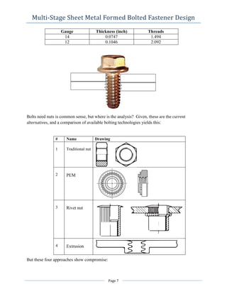
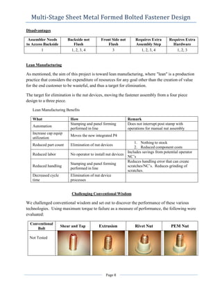
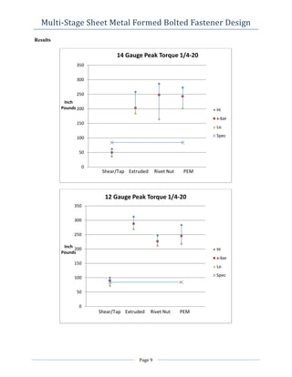
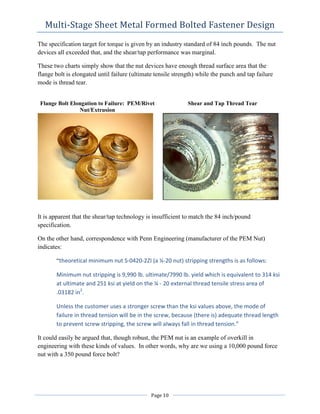
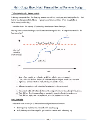

This document discusses the development of a multi-stage sheet metal fastening design that eliminates nuts to reduce costs and improve manufacturing efficiency. Testing showed that while extruded, rivet, and PEM nuts exceeded torque specifications, shear/tap fasteners only marginally met specifications, failing through thread tear. To breakthrough this technology barrier, the basics of thread forming were revisited. Roll-forming threads through compression may improve performance over cutting threads.


![ME 312 Mechanical Machine Design [Screws, Bolts, Nuts]](https://cdn.slidesharecdn.com/ss_thumbnails/me312-dsulec10-screws-170213050612-thumbnail.jpg?width=640&height=640&fit=bounds)


