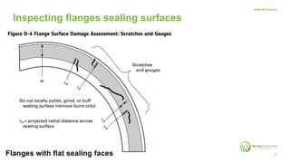
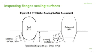
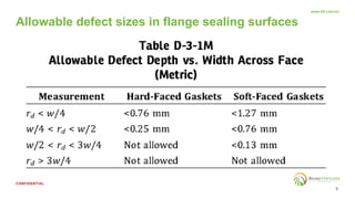
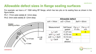
3. 4
CONFIDENTIAL
www.bfi.com.bn
Scope of ASME PCC-1
- These guidelines for bolted flange joint assemblies (BFJAs) apply principally to pressure-
boundary flanged joints with ring-type gaskets that are entirely within the circle enclosed by the
bolt holes and with no contact outside this circle.
These include all gaskets EXCEPT FULL FACE gaskets.
- The guidelines outlined in this document cover the assembly elements essential for a high level
of leak-tightness integrity of otherwise PROPERLY DESIGNED / CONSTRUCTED BFJAs.
4. 5
CONFIDENTIAL
www.bfi.com.bn
Cleaning of flanges & fastener contact surfaces
- Clean and examine flange and fastener contact surfaces.
- Remove all indications of the previous gasket installation from the gasket contact surfaces
- Use approved solvents and / or soft-wire brushes, if required, for cleaning to prevent surface contamination
and damage to existing surface finish.
- Avoid using carbon steel brushes on stainless steel flanges
Cleaning exception
The exception based on experience is residual flexible graphite that may remain in the surface finish
grooves, when either a flexible graphite clad or a spiral-wound gasket with flexible graphite filler is to be used
as the replacement gasket.
5. 6
CONFIDENTIAL
www.bfi.com.bn
Sealing Surface Imperfections
• Examine the gasket contact surfaces
of both mating joint flanges for damage
to surface finish such as scratches,
nicks, gouges, and burrs. Indications
running radially across the facing are
of particular concern.
Inspecting flanges sealing surfaces
9. 10
CONFIDENTIAL
www.bfi.com.bn
For example: we have a 4” 150# rating RF flange, which has two pits on its sealing face as shown in the
figure below.
Pit-1: 17mm wide radially & 1.2mm deep
Pit-2: 3mm wide radially & 1.2mm deep
Allowable defect
w/4 = 14mm w/2 = 27mm 3w/4 = 42mm
Measurement Soft faced
gasket
For rd =
17 mm
For rd = 3
mm
rd < w/4 <1.27 mm
w/4 < rd < w/2 <0.76 mm
w/2 < rd < 3w/4 <0.13 mm
rd > 3w/4 Not
allowed
Allowable defect sizes in flange sealing surfaces
10. 11
CONFIDENTIAL
www.bfi.com.bn
Sealing Surface Flatness check
• A flatness check is typically specified when working with large-diameter, problematic, or critical service
flanges with a history of leakage or suspect fabrication.
Flatness requirement for flange sealing surfaces
11. 12
CONFIDENTIAL
www.bfi.com.bn
• Examine bolt and nut threads andwasher faces of nuts for damage such as rust, corrosion, and burrs.
• Verify that each nut turns freely by hand past the location on the bolt where it will come to rest after
tightening.
• If the bolted joint assembly includes tapped hole threads, verify that the bolts thread by hand to the full
depth of the tapped holes.
What to look for?
• Dirty / clogged threads
• Bending of threads or thread damage due to over-tightening practices
• Reduction in thread diameter at a particular location on the bolt due to multiple times tightening / re-use.
• Charred, burred, cracked, pitted washers
• Washer material softer than the nut or flange material
Inspecting fasteners & washers
12. 13
CONFIDENTIAL
www.bfi.com.bn
How to assemble fastners correctly?
• effective lubrication of the bolts with an appropriate lubricant suitable for the service temperature
conditions.
• Apply the lubricant from the end of the stud to extend past the location where the nut face will rest
aftertightening.
Assembling fasteners & washers correctly
13. 14
CONFIDENTIAL
www.bfi.com.bn
• Application oflubricant after stud insertionminimizes the likelihood of contamination with foreign particles
such as rust,paint scale, sand, coke fines, or similar abrasive particles that could negatively affect
the overall nut factor.
• Do not apply lubricant on the gasket or gasket seating surfaces.
Assembling fasteners & washers correctly
14. 15
CONFIDENTIAL
www.bfi.com.bn
• Install the nut on one end of the stud with minimal thread protrusion such that any excess thread length
is located on the opposite end of the stud. This practice facilitates joint disassembly (attempting to
centering a longer bolt in the flange is old method and should not be practised anymore).
• Once the bolts and nuts are tightened, each nut bolt pair become unique from the other. So, donot mix
the nuts together after dis-assembling. Keep each nut bolt pair separately.
• If a replacement is necessary for any one item (either nut or bolt), it is recommended to replace both
items with new.
• If one bolt in a flange require replacement, it is recommended that all bolts be replaced. If all bolts cannot
be changed, and more than one bolt is changed, space them symmetrically around the bolt circle so that
they are surrounded by old fasteners.
• Avoid excessively long bolts. Excessive thread protrusion can complicate joint disassembly due to
corrosion, paint, or damage on the exposed thread.
• Do not exceed 10% of the total target assembly bolt load or torque value.
Assembling fasteners & washers correctly
15. 16
CONFIDENTIAL
www.bfi.com.bn
Short Bolting
• When the bolt threads fall short of mating with all the nut threads; is called short bolting. It
must be avoided.
• The minimum bolt protrusion through the nut is at least one thread of the bolt should be out of
the nut.
Assembling fasteners & washers correctly
19. 20
CONFIDENTIAL
www.bfi.com.bn
Correct Gasket Installation
• Examine the new gasket for damage or defects.
• Verify the gasket conforms to dimensions (O.D, I.D, thickness) and material
specifications.
• Position the gasket to be concentric with the flange I.D. such that the gasket is
supported during the positioning process.
• Verify that no portion of the gasket sealing face projects into the flow path.
• Secure the gasket in place, & ensure the gasket will remain in place during the
joint assembly process.
• Do not apply adhesive tape or grease on the gasket or flange sealing face. Only
use an appropriate adhesive spray (compatible with the flange & gasket
material) to secure the gasket in place.
20. 21
CONFIDENTIAL
www.bfi.com.bn
Flange tightening & torqueing
• Ensure to follow criss-cross (or star) tightening pattern.
• In case of lot of bolts on a flange, number the flanges to avoid forgetting the tightening sequence.
21. 22
CONFIDENTIAL
www.bfi.com.bn
Flange tightening & torqueing
No. of passes for tightening
Option-1: Conventional criss-cross pattern
Pass-1: all bolts tightened to 20 ~ 30% of tightening torque in criss-cross pattern.
Pass-2: all bolts tightened to 50 ~ 70% of tightening torque in criss-cross pattern.
Pass-3: all bolts tightened to 100% of tightening torque in criss-cross pattern
Pass-4: This pass follows circular pattern to check all the bolts at 100% torque.
Option-2: Quadrant pattern (accelerated version)
This option can be adapted for flanges having huge number of bolts to save time by eliminating repeated tool
movement during the 3 passes across all the bolts.
Pass-1: Bolt # 1 thru 4, tightened to 20 ~ 30% of tightening torque in criss-cross pattern.
Pass-2: Bolt # 1 thru 4, tightened to 50 ~ 70% of tightening torque in criss-cross pattern.
Pass-3: Bolt # 1 thru 4, tightened to 100% of tightening torque in criss-cross pattern.
Pass-4: All bolts tightened at 100% torque, using circular pattern.
22. 23
CONFIDENTIAL
www.bfi.com.bn
Flange tightening & torqueing
Important consideration:
The 3-pass torqueing method is good for thin-profile flat gaskets (e.g. spiral wound, full-face, RF gaskets,
flat metallic ring gaskets, and small-dia ring joint gaskets).
However, as the thickness of gaskets start increasing ( e.g. bigger size ring joint gaskets) or the gasket profile
/ geometry changes (e.g. lens ring gasket); it is recommended to increase the tightening passes to 4, to
break the torque value in relatively smaller steps, that will keep the flange alignment during tightening.
Yet another better way is to use multiple torque tools simultaneously to prevent flange-gasket misalignment
(such as the bolt tensioner tool, in which at-least 4 bridges are installed simultaneously for each torquing
pass).
23. 24
CONFIDENTIAL
www.bfi.com.bn
Flange tightening & torqueing
Start-up retorque (Hot torquing):
Flanges on high-temp services, usually undergo different expansion rates for bolts & flanges.
• The bolts expand at a higher rate at a given temperature as compared to the flanges. This is because they
are more concealed from the atmosphere and have much smaller surface area as compared to the
flanges, which prevent them to dissipate as much heat as the flanges can. This result in more thermal
expansion of bolts as compared to the flanges, which makes a joint loose and can cause leaks typically
characterised as “start-up” leaks.
• Once the flange-bolt assembly reaches a temperature equilibrium, the leak usually stops. However, in
some cases, having such a leak can be catastrophic (e.g. in high temp hydrogen service). In that case, it is
usually recommended to perform a start-up retorque to make up for any lost torque due to temperature
increase and avoid such leaks.
Start-up retorque is performed when the temperature of the flange or bolts is between 150°C (300°F) and
230°C (450°F) or within 24h of unit start-up if the joint temperature remains below 150°C (300°F). Start-up
retorque is carried out in circular pattern only, until the nuts no longer turn.
25. 26
CONFIDENTIAL
www.bfi.com.bn
Post-tightening activities
• Check high-low and gap measurement between flanges. The gap measurement should be done at 4-points
(0o, 90o, 180o, 270o) for small dia flanges; and at-least 8 equi-spaced points for large dia flanges.
• Use a measuring device such as vernier caliper or tapered wedge gage to get a precise measurement.
Avoid using the measuring tape. Ensure that the difference in the measured values is with-in prescribed
tolerance of 0.25mm.
26. 27
CONFIDENTIAL
www.bfi.com.bn
Flange Dis-assembly
• Step-1: Loosen one bolt completely. Note the total nut turns required to fully relieve the bolt load from
assembled to the finger-tight condition.
• Step-2: Retighten the loose bolt to 7∕8 of the total nut turn noted in Step 1.
• Step-3: In a circular pattern, loosen each bolt by 1∕8 ofthe total nut turn noted in Step 1.
• Step-4: Proceed with nut loosening in a circular pattern, removing all load on each stud.