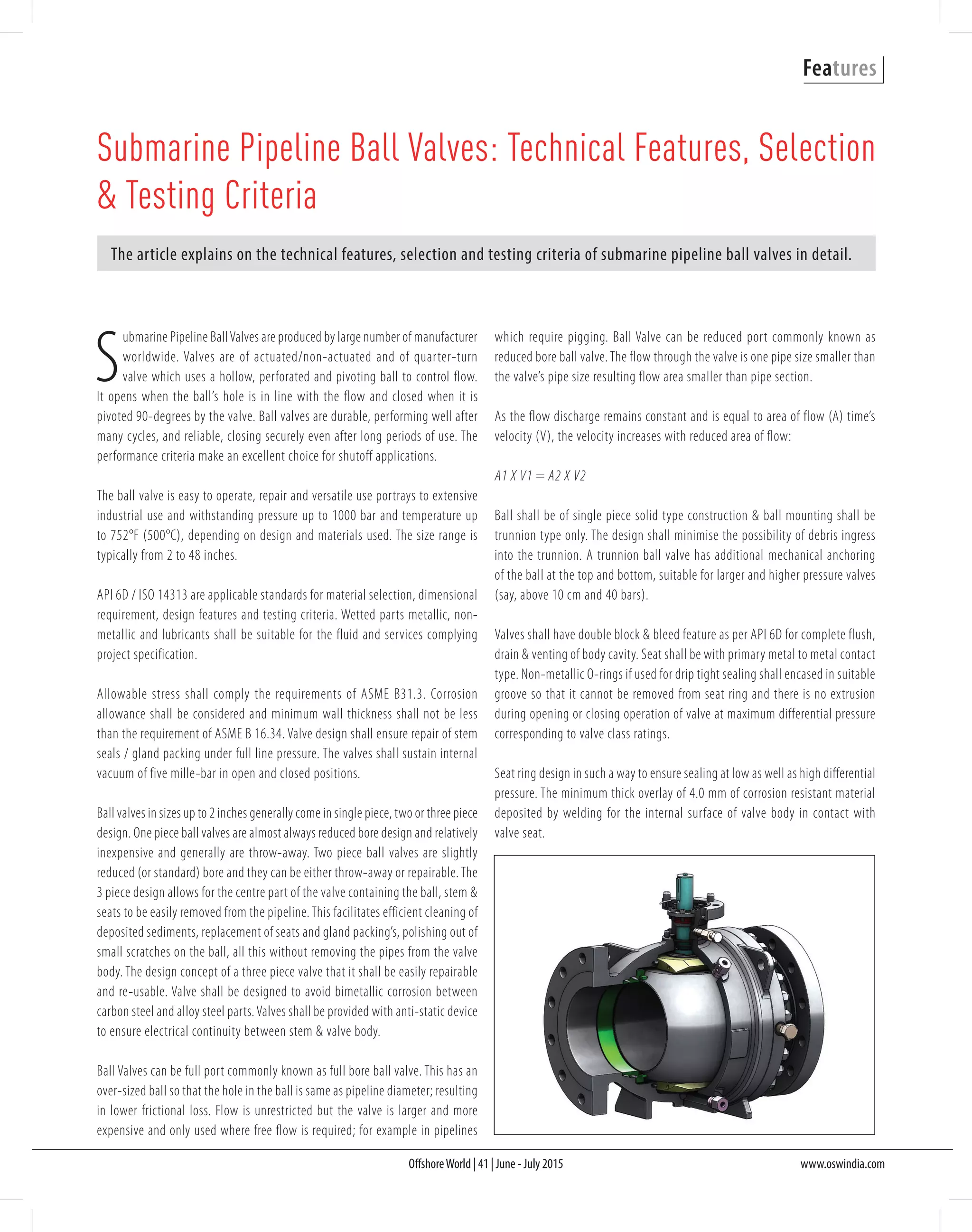
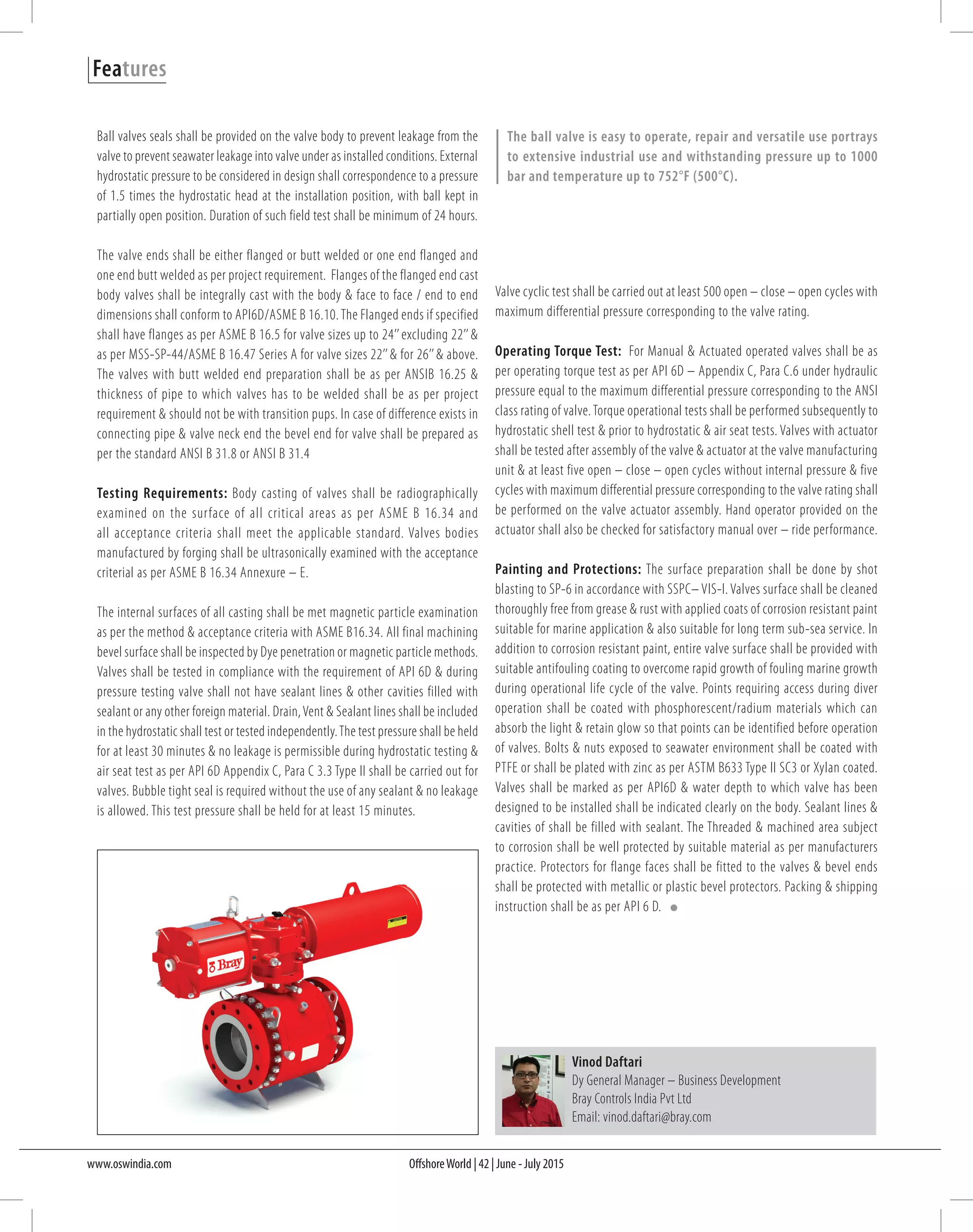
SlideShare a Scribd company logo
OffshoreWorld | 41 | June - July 2015 www.oswindia.com
Features
S
ubmarine Pipeline BallValves are produced by large number of manufacturer
worldwide. Valves are of actuated/non-actuated and of quarter-turn
valve which uses a hollow, perforated and pivoting ball to control flow.
It opens when the ball’s hole is in line with the flow and closed when it is
pivoted 90-degrees by the valve. Ball valves are durable, performing well after
many cycles, and reliable, closing securely even after long periods of use. The
performance criteria make an excellent choice for shutoff applications.
The ball valve is easy to operate, repair and versatile use portrays to extensive
industrial use and withstanding pressure up to 1000 bar and temperature up
to 752°F (500°C), depending on design and materials used. The size range is
typically from 2 to 48 inches.
API 6D / ISO 14313 are applicable standards for material selection, dimensional
requirement, design features and testing criteria. Wetted parts metallic, non-
metallic and lubricants shall be suitable for the fluid and services complying
project specification.
Allowable stress shall comply the requirements of ASME B31.3. Corrosion
allowance shall be considered and minimum wall thickness shall not be less
than the requirement of ASME B 16.34. Valve design shall ensure repair of stem
seals / gland packing under full line pressure. The valves shall sustain internal
vacuum of five mille-bar in open and closed positions.
Ball valves in sizes up to 2 inches generally come in single piece, two or three piece
design. One piece ball valves are almost always reduced bore design and relatively
inexpensive and generally are throw-away. Two piece ball valves are slightly
reduced (or standard) bore and they can be either throw-away or repairable.The
3 piece design allows for the centre part of the valve containing the ball, stem &
seats to be easily removed from the pipeline.This facilitates efficient cleaning of
deposited sediments, replacement of seats and gland packing’s, polishing out of
small scratches on the ball, all this without removing the pipes from the valve
body. The design concept of a three piece valve that it shall be easily repairable
and re-usable. Valve shall be designed to avoid bimetallic corrosion between
carbon steel and alloy steel parts.Valves shall be provided with anti-static device
to ensure electrical continuity between stem & valve body.
Ball Valves can be full port commonly known as full bore ball valve. This has an
over-sized ball so that the hole in the ball is same as pipeline diameter; resulting
in lower frictional loss. Flow is unrestricted but the valve is larger and more
expensive and only used where free flow is required; for example in pipelines
Submarine Pipeline Ball Valves: Technical Features, Selection
& Testing Criteria
The article explains on the technical features, selection and testing criteria of submarine pipeline ball valves in detail.
which require pigging. Ball Valve can be reduced port commonly known as
reduced bore ball valve. The flow through the valve is one pipe size smaller than
the valve’s pipe size resulting flow area smaller than pipe section.
As the flow discharge remains constant and is equal to area of flow (A) time’s
velocity (V), the velocity increases with reduced area of flow:
A1 X V1 = A2 X V2
Ball shall be of single piece solid type construction & ball mounting shall be
trunnion type only. The design shall minimise the possibility of debris ingress
into the trunnion. A trunnion ball valve has additional mechanical anchoring
of the ball at the top and bottom, suitable for larger and higher pressure valves
(say, above 10 cm and 40 bars).
Valves shall have double block & bleed feature as per API 6D for complete flush,
drain & venting of body cavity. Seat shall be with primary metal to metal contact
type. Non-metallic O-rings if used for drip tight sealing shall encased in suitable
groove so that it cannot be removed from seat ring and there is no extrusion
during opening or closing operation of valve at maximum differential pressure
corresponding to valve class ratings.
Seat ring design in such a way to ensure sealing at low as well as high differential
pressure. The minimum thick overlay of 4.0 mm of corrosion resistant material
deposited by welding for the internal surface of valve body in contact with
valve seat.
OffshoreWorld | 42 | June - July 2015www.oswindia.com
Features
Ball valves seals shall be provided on the valve body to prevent leakage from the
valve to prevent seawater leakage into valve under as installed conditions. External
hydrostatic pressure to be considered in design shall correspondence to a pressure
of 1.5 times the hydrostatic head at the installation position, with ball kept in
partially open position. Duration of such field test shall be minimum of 24 hours.
The valve ends shall be either flanged or butt welded or one end flanged and
one end butt welded as per project requirement. Flanges of the flanged end cast
body valves shall be integrally cast with the body & face to face / end to end
dimensions shall conform to API6D/ASME B 16.10.The Flanged ends if specified
shall have flanges as per ASME B 16.5 for valve sizes up to 24’’excluding 22’’&
as per MSS-SP-44/ASME B 16.47 Series A for valve sizes 22’’& for 26’’& above.
The valves with butt welded end preparation shall be as per ANSIB 16.25 &
thickness of pipe to which valves has to be welded shall be as per project
requirement & should not be with transition pups. In case of difference exists in
connecting pipe & valve neck end the bevel end for valve shall be prepared as
per the standard ANSI B 31.8 or ANSI B 31.4
Testing Requirements: Body casting of valves shall be radiographically
examined on the surface of all critical areas as per ASME B 16.34 and
all acceptance criteria shall meet the applicable standard. Valves bodies
manufactured by forging shall be ultrasonically examined with the acceptance
criterial as per ASME B 16.34 Annexure – E.
The internal surfaces of all casting shall be met magnetic particle examination
as per the method & acceptance criteria with ASME B16.34. All final machining
bevel surface shall be inspected by Dye penetration or magnetic particle methods.
Valves shall be tested in compliance with the requirement of API 6D & during
pressure testing valve shall not have sealant lines & other cavities filled with
sealant or any other foreign material. Drain,Vent & Sealant lines shall be included
in the hydrostatic shall test or tested independently.The test pressure shall be held
for at least 30 minutes & no leakage is permissible during hydrostatic testing &
air seat test as per API 6D Appendix C, Para C 3.3 Type II shall be carried out for
valves. Bubble tight seal is required without the use of any sealant & no leakage
is allowed. This test pressure shall be held for at least 15 minutes.
Vinod Daftari
Dy General Manager – Business Development
Bray Controls India Pvt Ltd
Email: vinod.daftari@bray.com
Valve cyclic test shall be carried out at least 500 open – close – open cycles with
maximum differential pressure corresponding to the valve rating.
Operating Torque Test: For Manual & Actuated operated valves shall be as
per operating torque test as per API 6D – Appendix C, Para C.6 under hydraulic
pressure equal to the maximum differential pressure corresponding to the ANSI
class rating of valve.Torque operational tests shall be performed subsequently to
hydrostatic shell test & prior to hydrostatic & air seat tests. Valves with actuator
shall be tested after assembly of the valve & actuator at the valve manufacturing
unit & at least five open – close – open cycles without internal pressure & five
cycles with maximum differential pressure corresponding to the valve rating shall
be performed on the valve actuator assembly. Hand operator provided on the
actuator shall also be checked for satisfactory manual over – ride performance.
Painting and Protections: The surface preparation shall be done by shot
blasting to SP-6 in accordance with SSPC– VIS-I. Valves surface shall be cleaned
thoroughly free from grease & rust with applied coats of corrosion resistant paint
suitable for marine application & also suitable for long term sub-sea service. In
addition to corrosion resistant paint, entire valve surface shall be provided with
suitable antifouling coating to overcome rapid growth of fouling marine growth
during operational life cycle of the valve. Points requiring access during diver
operation shall be coated with phosphorescent/radium materials which can
absorb the light & retain glow so that points can be identified before operation
of valves. Bolts & nuts exposed to seawater environment shall be coated with
PTFE or shall be plated with zinc as per ASTM B633 Type II SC3 or Xylan coated.
Valves shall be marked as per API6D & water depth to which valve has been
designed to be installed shall be indicated clearly on the body. Sealant lines &
cavities of shall be filled with sealant. The Threaded & machined area subject
to corrosion shall be well protected by suitable material as per manufacturers
practice. Protectors for flange faces shall be fitted to the valves & bevel ends
shall be protected with metallic or plastic bevel protectors. Packing & shipping
instruction shall be as per API 6 D.
The ball valve is easy to operate, repair and versatile use portrays
to extensive industrial use and withstanding pressure up to 1000
bar and temperature up to 752°F (500°C).

More Related Content

What's hot

Branch connections
Branch connectionsBranch connections
Branch connections
Nazar Abdul Kareem Hussein
 
Floating Ball Valve, Floating Ball Valve Oilfield Equipment- WOM Group
Floating Ball Valve, Floating Ball Valve Oilfield Equipment- WOM GroupFloating Ball Valve, Floating Ball Valve Oilfield Equipment- WOM Group
Floating Ball Valve, Floating Ball Valve Oilfield Equipment- WOM Group
womgroup
 
Trsv overview external
Trsv overview externalTrsv overview external
Trsv overview externalManuel Coxe
 
Wellhead
WellheadWellhead
Wellhead
amrhaggag
 
Terofox dual check, butterfly (rev.00)
Terofox dual check, butterfly (rev.00) Terofox dual check, butterfly (rev.00)
Terofox dual check, butterfly (rev.00)
Terofox Valves Integrated Corp.
 
Terofox api609 resilient seated butterfly valve (rev.00)
Terofox api609 resilient seated butterfly valve (rev.00)Terofox api609 resilient seated butterfly valve (rev.00)
Terofox api609 resilient seated butterfly valve (rev.00)
Terofox Valves Integrated Corp.
 
Blow out preventer (bop)
Blow out preventer (bop)Blow out preventer (bop)
Blow out preventer (bop)danperth
 
GWC Valve International Forged Steel Gate, Globe, and Check
GWC Valve International Forged Steel Gate, Globe, and CheckGWC Valve International Forged Steel Gate, Globe, and Check
GWC Valve International Forged Steel Gate, Globe, and Check
GWC Valve International
 
complete guide to process valves
complete guide to process valves complete guide to process valves
complete guide to process valves
Elsayed Amer
 
Subsurface flow controls external
Subsurface flow controls externalSubsurface flow controls external
Subsurface flow controls externalBladimir R
 
Valves pipe fittings
Valves pipe fittingsValves pipe fittings
Valves pipe fittings
Roberto Dela Cruz
 
Hwayoo - Lubricator assembly
Hwayoo - Lubricator assemblyHwayoo - Lubricator assembly
Hwayoo - Lubricator assemblyHwayoo Petroleum
 
Avcon presentation
Avcon presentationAvcon presentation
Avcon presentation
vijay oak
 
10 flanges gaskets & fasteners
10 flanges gaskets & fasteners10 flanges gaskets & fasteners
10 flanges gaskets & fasteners
cahngawi1981
 
Valves operation and functions complete guide
Valves operation and functions complete guideValves operation and functions complete guide
Valves operation and functions complete guide
Elsayed Amer
 
Válvulas de mariposa - Butterfly Valves
Válvulas de mariposa - Butterfly ValvesVálvulas de mariposa - Butterfly Valves
Válvulas de mariposa - Butterfly Valves
JLX Valve
 
Liquid level specification
Liquid level specificationLiquid level specification
Liquid level specification
IPEC
 

What's hot (18)

Branch connections
Branch connectionsBranch connections
Branch connections
 
Floating Ball Valve, Floating Ball Valve Oilfield Equipment- WOM Group
Floating Ball Valve, Floating Ball Valve Oilfield Equipment- WOM GroupFloating Ball Valve, Floating Ball Valve Oilfield Equipment- WOM Group
Floating Ball Valve, Floating Ball Valve Oilfield Equipment- WOM Group
 
Trsv overview external
Trsv overview externalTrsv overview external
Trsv overview external
 
Wellhead
WellheadWellhead
Wellhead
 
Terofox dual check, butterfly (rev.00)
Terofox dual check, butterfly (rev.00) Terofox dual check, butterfly (rev.00)
Terofox dual check, butterfly (rev.00)
 
Terofox api609 resilient seated butterfly valve (rev.00)
Terofox api609 resilient seated butterfly valve (rev.00)Terofox api609 resilient seated butterfly valve (rev.00)
Terofox api609 resilient seated butterfly valve (rev.00)
 
Blow out preventer (bop)
Blow out preventer (bop)Blow out preventer (bop)
Blow out preventer (bop)
 
GWC Valve International Forged Steel Gate, Globe, and Check
GWC Valve International Forged Steel Gate, Globe, and CheckGWC Valve International Forged Steel Gate, Globe, and Check
GWC Valve International Forged Steel Gate, Globe, and Check
 
complete guide to process valves
complete guide to process valves complete guide to process valves
complete guide to process valves
 
Subsurface flow controls external
Subsurface flow controls externalSubsurface flow controls external
Subsurface flow controls external
 
Valves pipe fittings
Valves pipe fittingsValves pipe fittings
Valves pipe fittings
 
Hwayoo - Lubricator assembly
Hwayoo - Lubricator assemblyHwayoo - Lubricator assembly
Hwayoo - Lubricator assembly
 
Avcon presentation
Avcon presentationAvcon presentation
Avcon presentation
 
10 flanges gaskets & fasteners
10 flanges gaskets & fasteners10 flanges gaskets & fasteners
10 flanges gaskets & fasteners
 
Valves operation and functions complete guide
Valves operation and functions complete guideValves operation and functions complete guide
Valves operation and functions complete guide
 
Válvulas de mariposa - Butterfly Valves
Válvulas de mariposa - Butterfly ValvesVálvulas de mariposa - Butterfly Valves
Válvulas de mariposa - Butterfly Valves
 
KLOK-36-37-Brochure
KLOK-36-37-BrochureKLOK-36-37-Brochure
KLOK-36-37-Brochure
 
Liquid level specification
Liquid level specificationLiquid level specification
Liquid level specification
 

Similar to Submarine Pipeline Ball Valves

Hwayoo - Wellhead Equipment & Christmass Tree 20160802
Hwayoo - Wellhead Equipment & Christmass Tree 20160802Hwayoo - Wellhead Equipment & Christmass Tree 20160802
Hwayoo - Wellhead Equipment & Christmass Tree 20160802Hwayoo Petroleum
 
74 57 catalogue-of-ball-valves
74 57 catalogue-of-ball-valves74 57 catalogue-of-ball-valves
74 57 catalogue-of-ball-valves
Remaval S.A.S Domotica Mantenimiento
 
Control Valve and Types of caged trims
Control Valve and Types of caged trimsControl Valve and Types of caged trims
Control Valve and Types of caged trims
naz4u
 
Expert knife gate-valves
Expert knife gate-valvesExpert knife gate-valves
Expert knife gate-valvessachindesai055
 
Valvulas globo - Globe valves
Valvulas globo - Globe valvesValvulas globo - Globe valves
Valvulas globo - Globe valves
JLX Valve
 
GWC Valve International Pressure Seal Valves
GWC Valve International Pressure Seal ValvesGWC Valve International Pressure Seal Valves
GWC Valve International Pressure Seal Valves
GWC Valve International
 
KDV WT Brochure 100510
KDV WT Brochure 100510KDV WT Brochure 100510
KDV WT Brochure 100510Ilan Almagor
 
Our company presentation copy
Our company presentation    copyOur company presentation    copy
Our company presentation copy
Aqab Engineers
 
Technical data sheet
Technical data sheetTechnical data sheet
Technical data sheet
Niladri Bhattacharyya
 
Change-over-valve-Catalog_EN (1)
Change-over-valve-Catalog_EN (1)Change-over-valve-Catalog_EN (1)
Change-over-valve-Catalog_EN (1)Leser UK
 
NEWCON Knife Gate Valve for Slurry Application
NEWCON Knife Gate Valve for Slurry ApplicationNEWCON Knife Gate Valve for Slurry Application
NEWCON Knife Gate Valve for Slurry Application
Adroitt Flow Control Pvt Ltd
 
Floating Ball Valve, Floating Ball Valve Manufacturers - WOM Group
Floating Ball Valve, Floating Ball Valve Manufacturers - WOM GroupFloating Ball Valve, Floating Ball Valve Manufacturers - WOM Group
Floating Ball Valve, Floating Ball Valve Manufacturers - WOM Group
womgroup
 
Floating Ball Valve, Floating Ball Valve Surface Equipment - WOM Group
Floating Ball Valve, Floating Ball Valve Surface Equipment - WOM GroupFloating Ball Valve, Floating Ball Valve Surface Equipment - WOM Group
Floating Ball Valve, Floating Ball Valve Surface Equipment - WOM Group
womgroup
 
Severe Service Control & Isolation Valves in the Refining Industry
Severe Service Control & Isolation Valves in the Refining IndustrySevere Service Control & Isolation Valves in the Refining Industry
Severe Service Control & Isolation Valves in the Refining Industry
CTi Controltech
 
Pump api 675 presentation
Pump api 675 presentationPump api 675 presentation
Pump api 675 presentation
Vothanh Trung
 
Wellhead equipment Introduction Based on API 6a & NACE
Wellhead equipment Introduction Based on API 6a & NACEWellhead equipment Introduction Based on API 6a & NACE
Wellhead equipment Introduction Based on API 6a & NACE
Amir Rafati
 
Determination of Range of Splash of Testing Fluid during Hydro Testing of Kni...
Determination of Range of Splash of Testing Fluid during Hydro Testing of Kni...Determination of Range of Splash of Testing Fluid during Hydro Testing of Kni...
Determination of Range of Splash of Testing Fluid during Hydro Testing of Kni...
ijtsrd
 
Knife Edge Gate Valve
Knife Edge Gate ValveKnife Edge Gate Valve
Knife Edge Gate Valve
KEROMIYONS INTECH PRIVATE LIMITED
 
Lined Ball Valves Provide Corrosion Protection
Lined Ball Valves Provide Corrosion ProtectionLined Ball Valves Provide Corrosion Protection
Lined Ball Valves Provide Corrosion Protection
CTi Controltech
 

Similar to Submarine Pipeline Ball Valves (20)

Control valves
Control  valvesControl  valves
Control valves
 
Hwayoo - Wellhead Equipment & Christmass Tree 20160802
Hwayoo - Wellhead Equipment & Christmass Tree 20160802Hwayoo - Wellhead Equipment & Christmass Tree 20160802
Hwayoo - Wellhead Equipment & Christmass Tree 20160802
 
74 57 catalogue-of-ball-valves
74 57 catalogue-of-ball-valves74 57 catalogue-of-ball-valves
74 57 catalogue-of-ball-valves
 
Control Valve and Types of caged trims
Control Valve and Types of caged trimsControl Valve and Types of caged trims
Control Valve and Types of caged trims
 
Expert knife gate-valves
Expert knife gate-valvesExpert knife gate-valves
Expert knife gate-valves
 
Valvulas globo - Globe valves
Valvulas globo - Globe valvesValvulas globo - Globe valves
Valvulas globo - Globe valves
 
GWC Valve International Pressure Seal Valves
GWC Valve International Pressure Seal ValvesGWC Valve International Pressure Seal Valves
GWC Valve International Pressure Seal Valves
 
KDV WT Brochure 100510
KDV WT Brochure 100510KDV WT Brochure 100510
KDV WT Brochure 100510
 
Our company presentation copy
Our company presentation    copyOur company presentation    copy
Our company presentation copy
 
Technical data sheet
Technical data sheetTechnical data sheet
Technical data sheet
 
Change-over-valve-Catalog_EN (1)
Change-over-valve-Catalog_EN (1)Change-over-valve-Catalog_EN (1)
Change-over-valve-Catalog_EN (1)
 
NEWCON Knife Gate Valve for Slurry Application
NEWCON Knife Gate Valve for Slurry ApplicationNEWCON Knife Gate Valve for Slurry Application
NEWCON Knife Gate Valve for Slurry Application
 
Floating Ball Valve, Floating Ball Valve Manufacturers - WOM Group
Floating Ball Valve, Floating Ball Valve Manufacturers - WOM GroupFloating Ball Valve, Floating Ball Valve Manufacturers - WOM Group
Floating Ball Valve, Floating Ball Valve Manufacturers - WOM Group
 
Floating Ball Valve, Floating Ball Valve Surface Equipment - WOM Group
Floating Ball Valve, Floating Ball Valve Surface Equipment - WOM GroupFloating Ball Valve, Floating Ball Valve Surface Equipment - WOM Group
Floating Ball Valve, Floating Ball Valve Surface Equipment - WOM Group
 
Severe Service Control & Isolation Valves in the Refining Industry
Severe Service Control & Isolation Valves in the Refining IndustrySevere Service Control & Isolation Valves in the Refining Industry
Severe Service Control & Isolation Valves in the Refining Industry
 
Pump api 675 presentation
Pump api 675 presentationPump api 675 presentation
Pump api 675 presentation
 
Wellhead equipment Introduction Based on API 6a & NACE
Wellhead equipment Introduction Based on API 6a & NACEWellhead equipment Introduction Based on API 6a & NACE
Wellhead equipment Introduction Based on API 6a & NACE
 
Determination of Range of Splash of Testing Fluid during Hydro Testing of Kni...
Determination of Range of Splash of Testing Fluid during Hydro Testing of Kni...Determination of Range of Splash of Testing Fluid during Hydro Testing of Kni...
Determination of Range of Splash of Testing Fluid during Hydro Testing of Kni...
 
Knife Edge Gate Valve
Knife Edge Gate ValveKnife Edge Gate Valve
Knife Edge Gate Valve
 
Lined Ball Valves Provide Corrosion Protection
Lined Ball Valves Provide Corrosion ProtectionLined Ball Valves Provide Corrosion Protection
Lined Ball Valves Provide Corrosion Protection
 

Submarine Pipeline Ball Valves

  • 1. OffshoreWorld | 41 | June - July 2015 www.oswindia.com Features S ubmarine Pipeline BallValves are produced by large number of manufacturer worldwide. Valves are of actuated/non-actuated and of quarter-turn valve which uses a hollow, perforated and pivoting ball to control flow. It opens when the ball’s hole is in line with the flow and closed when it is pivoted 90-degrees by the valve. Ball valves are durable, performing well after many cycles, and reliable, closing securely even after long periods of use. The performance criteria make an excellent choice for shutoff applications. The ball valve is easy to operate, repair and versatile use portrays to extensive industrial use and withstanding pressure up to 1000 bar and temperature up to 752°F (500°C), depending on design and materials used. The size range is typically from 2 to 48 inches. API 6D / ISO 14313 are applicable standards for material selection, dimensional requirement, design features and testing criteria. Wetted parts metallic, non- metallic and lubricants shall be suitable for the fluid and services complying project specification. Allowable stress shall comply the requirements of ASME B31.3. Corrosion allowance shall be considered and minimum wall thickness shall not be less than the requirement of ASME B 16.34. Valve design shall ensure repair of stem seals / gland packing under full line pressure. The valves shall sustain internal vacuum of five mille-bar in open and closed positions. Ball valves in sizes up to 2 inches generally come in single piece, two or three piece design. One piece ball valves are almost always reduced bore design and relatively inexpensive and generally are throw-away. Two piece ball valves are slightly reduced (or standard) bore and they can be either throw-away or repairable.The 3 piece design allows for the centre part of the valve containing the ball, stem & seats to be easily removed from the pipeline.This facilitates efficient cleaning of deposited sediments, replacement of seats and gland packing’s, polishing out of small scratches on the ball, all this without removing the pipes from the valve body. The design concept of a three piece valve that it shall be easily repairable and re-usable. Valve shall be designed to avoid bimetallic corrosion between carbon steel and alloy steel parts.Valves shall be provided with anti-static device to ensure electrical continuity between stem & valve body. Ball Valves can be full port commonly known as full bore ball valve. This has an over-sized ball so that the hole in the ball is same as pipeline diameter; resulting in lower frictional loss. Flow is unrestricted but the valve is larger and more expensive and only used where free flow is required; for example in pipelines Submarine Pipeline Ball Valves: Technical Features, Selection & Testing Criteria The article explains on the technical features, selection and testing criteria of submarine pipeline ball valves in detail. which require pigging. Ball Valve can be reduced port commonly known as reduced bore ball valve. The flow through the valve is one pipe size smaller than the valve’s pipe size resulting flow area smaller than pipe section. As the flow discharge remains constant and is equal to area of flow (A) time’s velocity (V), the velocity increases with reduced area of flow: A1 X V1 = A2 X V2 Ball shall be of single piece solid type construction & ball mounting shall be trunnion type only. The design shall minimise the possibility of debris ingress into the trunnion. A trunnion ball valve has additional mechanical anchoring of the ball at the top and bottom, suitable for larger and higher pressure valves (say, above 10 cm and 40 bars). Valves shall have double block & bleed feature as per API 6D for complete flush, drain & venting of body cavity. Seat shall be with primary metal to metal contact type. Non-metallic O-rings if used for drip tight sealing shall encased in suitable groove so that it cannot be removed from seat ring and there is no extrusion during opening or closing operation of valve at maximum differential pressure corresponding to valve class ratings. Seat ring design in such a way to ensure sealing at low as well as high differential pressure. The minimum thick overlay of 4.0 mm of corrosion resistant material deposited by welding for the internal surface of valve body in contact with valve seat.
  • 2. OffshoreWorld | 42 | June - July 2015www.oswindia.com Features Ball valves seals shall be provided on the valve body to prevent leakage from the valve to prevent seawater leakage into valve under as installed conditions. External hydrostatic pressure to be considered in design shall correspondence to a pressure of 1.5 times the hydrostatic head at the installation position, with ball kept in partially open position. Duration of such field test shall be minimum of 24 hours. The valve ends shall be either flanged or butt welded or one end flanged and one end butt welded as per project requirement. Flanges of the flanged end cast body valves shall be integrally cast with the body & face to face / end to end dimensions shall conform to API6D/ASME B 16.10.The Flanged ends if specified shall have flanges as per ASME B 16.5 for valve sizes up to 24’’excluding 22’’& as per MSS-SP-44/ASME B 16.47 Series A for valve sizes 22’’& for 26’’& above. The valves with butt welded end preparation shall be as per ANSIB 16.25 & thickness of pipe to which valves has to be welded shall be as per project requirement & should not be with transition pups. In case of difference exists in connecting pipe & valve neck end the bevel end for valve shall be prepared as per the standard ANSI B 31.8 or ANSI B 31.4 Testing Requirements: Body casting of valves shall be radiographically examined on the surface of all critical areas as per ASME B 16.34 and all acceptance criteria shall meet the applicable standard. Valves bodies manufactured by forging shall be ultrasonically examined with the acceptance criterial as per ASME B 16.34 Annexure – E. The internal surfaces of all casting shall be met magnetic particle examination as per the method & acceptance criteria with ASME B16.34. All final machining bevel surface shall be inspected by Dye penetration or magnetic particle methods. Valves shall be tested in compliance with the requirement of API 6D & during pressure testing valve shall not have sealant lines & other cavities filled with sealant or any other foreign material. Drain,Vent & Sealant lines shall be included in the hydrostatic shall test or tested independently.The test pressure shall be held for at least 30 minutes & no leakage is permissible during hydrostatic testing & air seat test as per API 6D Appendix C, Para C 3.3 Type II shall be carried out for valves. Bubble tight seal is required without the use of any sealant & no leakage is allowed. This test pressure shall be held for at least 15 minutes. Vinod Daftari Dy General Manager – Business Development Bray Controls India Pvt Ltd Email: vinod.daftari@bray.com Valve cyclic test shall be carried out at least 500 open – close – open cycles with maximum differential pressure corresponding to the valve rating. Operating Torque Test: For Manual & Actuated operated valves shall be as per operating torque test as per API 6D – Appendix C, Para C.6 under hydraulic pressure equal to the maximum differential pressure corresponding to the ANSI class rating of valve.Torque operational tests shall be performed subsequently to hydrostatic shell test & prior to hydrostatic & air seat tests. Valves with actuator shall be tested after assembly of the valve & actuator at the valve manufacturing unit & at least five open – close – open cycles without internal pressure & five cycles with maximum differential pressure corresponding to the valve rating shall be performed on the valve actuator assembly. Hand operator provided on the actuator shall also be checked for satisfactory manual over – ride performance. Painting and Protections: The surface preparation shall be done by shot blasting to SP-6 in accordance with SSPC– VIS-I. Valves surface shall be cleaned thoroughly free from grease & rust with applied coats of corrosion resistant paint suitable for marine application & also suitable for long term sub-sea service. In addition to corrosion resistant paint, entire valve surface shall be provided with suitable antifouling coating to overcome rapid growth of fouling marine growth during operational life cycle of the valve. Points requiring access during diver operation shall be coated with phosphorescent/radium materials which can absorb the light & retain glow so that points can be identified before operation of valves. Bolts & nuts exposed to seawater environment shall be coated with PTFE or shall be plated with zinc as per ASTM B633 Type II SC3 or Xylan coated. Valves shall be marked as per API6D & water depth to which valve has been designed to be installed shall be indicated clearly on the body. Sealant lines & cavities of shall be filled with sealant. The Threaded & machined area subject to corrosion shall be well protected by suitable material as per manufacturers practice. Protectors for flange faces shall be fitted to the valves & bevel ends shall be protected with metallic or plastic bevel protectors. Packing & shipping instruction shall be as per API 6 D. The ball valve is easy to operate, repair and versatile use portrays to extensive industrial use and withstanding pressure up to 1000 bar and temperature up to 752°F (500°C).