Downloaded 311 times


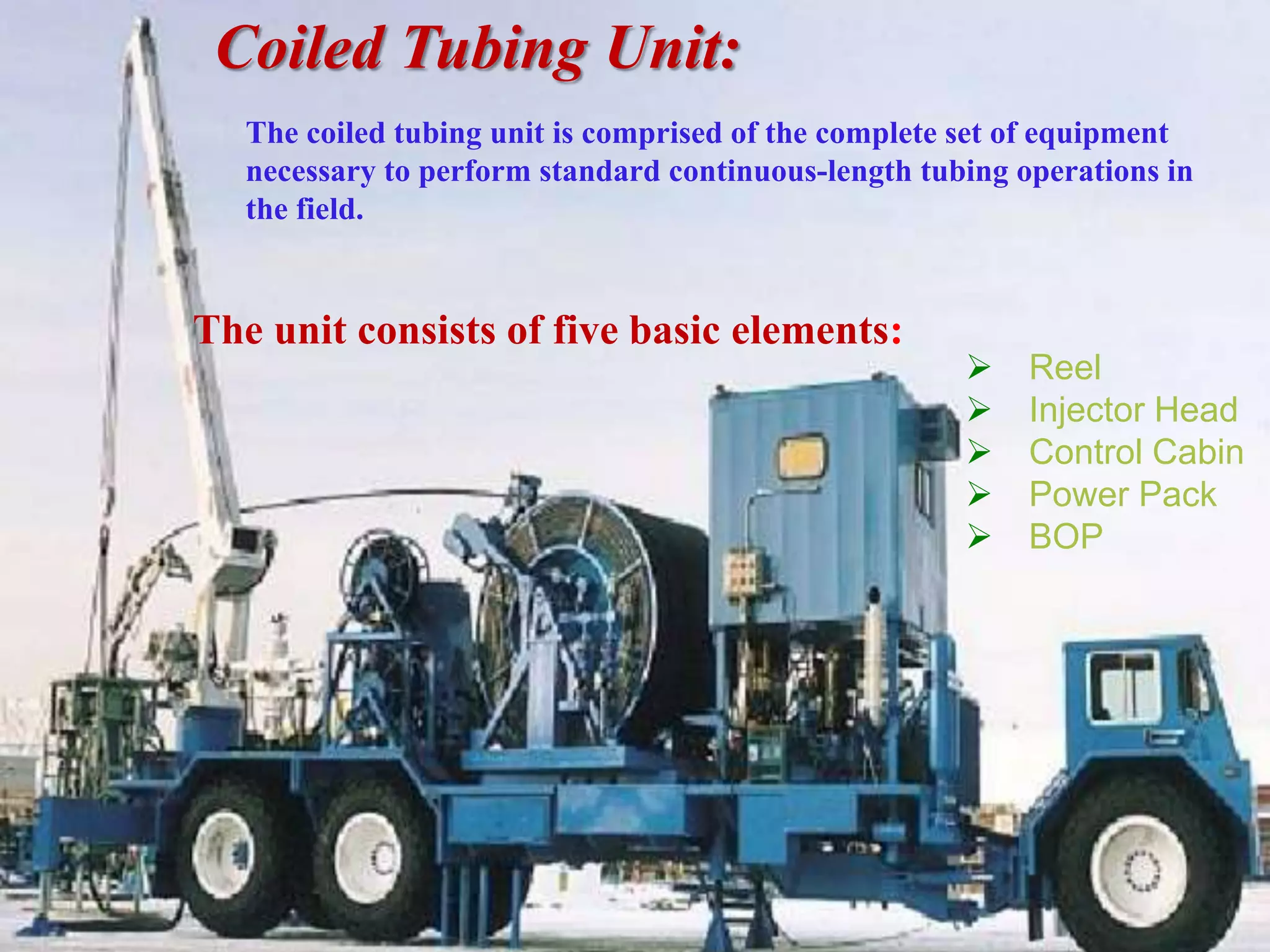


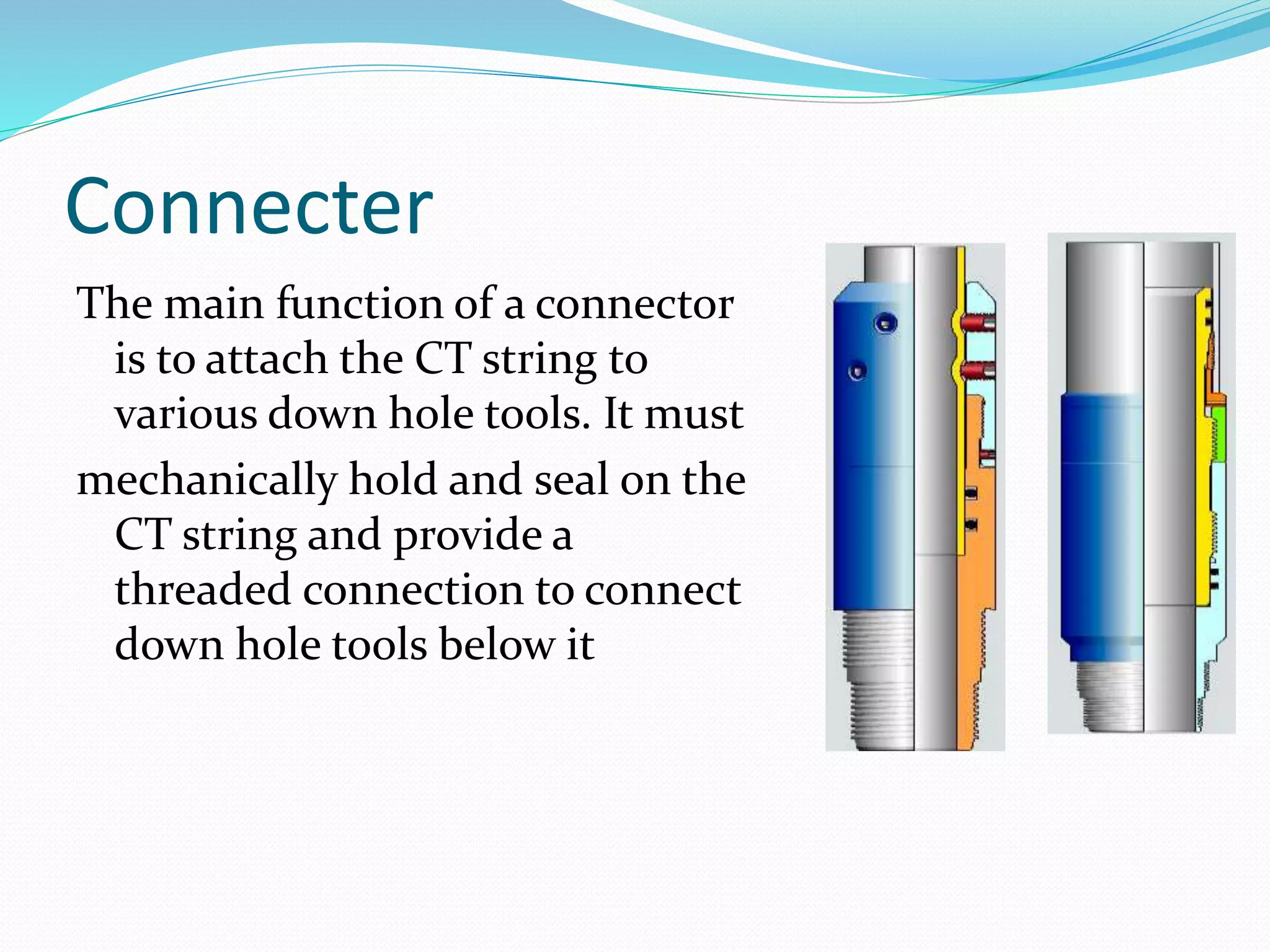


This document discusses well intervention techniques using coiled tubing. It describes coiled tubing as continuously-milled tubular product that is straightened before insertion into the wellbore. The main types of well intervention discussed are pumping, slickline, snubbing, workover, and coiled tubing. It provides details on the components and functions of a coiled tubing unit, including the reel, injector head, control cabin, power pack, blowout preventer, stripper, and bottom hole assembly.