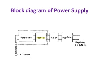
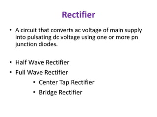
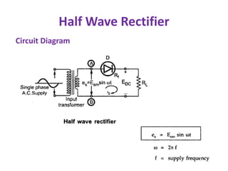
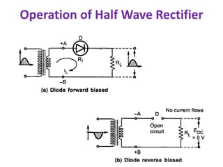
Rectifiers
R.Ramalakshmi
Assistant Professor
Ramco Institute of Technology
Rajapalayam
Block diagram of Power Supply
Rectifier
• A circuit that converts ac voltage of main supply
into pulsating dc voltage using one or more pn
junction diodes.
• Half Wave Rectifier
• Full Wave Rectifier
• Center Tap Rectifier
• Bridge Rectifier
Important Characteristics of Rectifier
• Waveform of the load current
• Regulation of output voltage
• Rectifier efficiency
• Peak value of current in the rectifier circuit
• Peak value of voltage across the rectifier
element in the reverse direction ( PIV)
• Ripple factor
Half Wave Rectifier
Circuit Diagram
Operation of Half Wave Rectifier
Waveform of Half Wave Rectifier
Average DC load Current (IDC )
Average DC voltage (Edc)
RMS Load Current (Irms)
RMS Load Voltage (Erms)
DC Power Delivered to the load
AC input power from transformer
secondary
How effectively a rectifier converts
ac into dc:
• Rectifier Efficiency (η)
• Ripple Factor (r)
Rectifier Efficiency (η)
Tells us the percentage of total input ac power
that is converted into useful dc output power.
η = 40.6 %
Under best conditions (no diode loss) only 40.6% of the
ac input power is converted into dc power.
The rest remains as the ac power in the load
Ripple Factor
Measure of purity of the dc output of a rectifier
Defined as the ratio of ac component of the output
wave to the dc component in the wave
Ripple Factor
This indicates that the ripple content in the output are 1.211 times the dc component.
i.e. 121.1 % of dc component.
The ripple factor is very high.
Therefore a half wave rectifier is a poor converter of ac to dc.
The ripple factor is minimized using filter circuits along with the rectifier.
Peak Inverse Voltage (PIV)
PIV = Em
Diode must be selected based on the PIV rating and
the circuit specification.
Disadvantage of HWR
•The ripple factor of half wave rectifier is 1.21,
which is quite high.
•The output contains lot of ripples
•The maximum theoretical efficiency is 40%.
•The practical value will be quite less than this.
•This indicates that HWR is quite inefficient.
Full WaveRectifier
Working of Center Tap Rectifier
Current Flow during the positive half of the input cycle
Current Flow during the negative half of the input cycle
Waveforms
Average DC current
Average (DC) Voltage
RMS Load Current (Irms)
RMS Load Voltage
DC Output Power
AC input power (Pac)
Rectifier Efficiency (η)
Ripple Factor
This indicates that the ripple contents in the output are 48%
of the dc component which is much less than that for the
half wave rectifier.
Peak Inverse Voltage
Advantages of Full Wave Rectifier
• Efficiency is higher.
• The large dc power output
• The ripple factor is less
Disadvantages of Full Wave Rectifier
• PIV rating of diode is higher.
• Higher PIV diodes are larger in size and costlier.
• The cost of center tap transformer is high.
Bridge Rectifier
Working of Bridge Rectifier
Waveforms of Bridge Rectifier
Parameters :
Advantages of Bridge Rectifier
• It does not need center tap transformer secondary.
• The transformer secondary voltage of CT rectifier is
2Vm, where as in Bridge the transformer secondary
must have a peak voltage of Vm. That is the
transformer secondary of CT rectifier must have double
the number of turns. Such transformers are costlier.
• If stepping up or stepping down of voltage is not
needed, we may even do away without transformer.
• Each diode in center tap has a PIV rating of 2Vm,
whereas diodes in bridge rectifier needs a PIV rating of
Vm. Hence the diodes for use in center tap rectifier are
costlier than meant for bridge rectifier.
Disadvantages of Bridge Rectifier
• It requires four diodes, two of which conduct
in alternate half cycles. This creates a total
voltage drop of 1.4V (if Si diodes are used).
• Therefore this creates a problem if low dc
voltage is required.
• The secondary voltage is low and two diode
voltage drop of 1.4V becomes significant.
Applications of Rectifiers
• Mobile chargers
• Laptop adapters
TUF-Transformer Utilization Factor
• The factor which indicates how much is the
utilization of the transformer in the circuit is
called TUF.
• It is defined as the ratio of dc power delivered to
the load to the ac power rating of the
transformer.
• For HWR, TUF = 0.287; Transformer is utilized less
• For FWR, TUF = 0.693; Transformer is utilized
more.
REFERENCES
• 1. Donald. A. Neamen, Electronic Circuits
Analysis and Design, 3rd Edition, Mc Graw Hill
Education (India) Private Ltd., 2010.
• 2. Robert L. Boylestad and Louis Nasheresky,
―Electronic Devices and Circuit Theory, 11th
Edition, Pearson Education, 2013.
Thank You

Rectifiers

  • 1.
  • 2.
    Block diagram ofPower Supply
  • 3.
    Rectifier • A circuitthat converts ac voltage of main supply into pulsating dc voltage using one or more pn junction diodes. • Half Wave Rectifier • Full Wave Rectifier • Center Tap Rectifier • Bridge Rectifier
  • 4.
    Important Characteristics ofRectifier • Waveform of the load current • Regulation of output voltage • Rectifier efficiency • Peak value of current in the rectifier circuit • Peak value of voltage across the rectifier element in the reverse direction ( PIV) • Ripple factor
  • 5.
  • 6.
    Operation of HalfWave Rectifier
  • 7.
    Waveform of HalfWave Rectifier
  • 8.
    Average DC loadCurrent (IDC )
  • 9.
  • 10.
    RMS Load Current(Irms) RMS Load Voltage (Erms)
  • 11.
    DC Power Deliveredto the load
  • 12.
    AC input powerfrom transformer secondary
  • 13.
    How effectively arectifier converts ac into dc: • Rectifier Efficiency (η) • Ripple Factor (r)
  • 14.
    Rectifier Efficiency (η) Tellsus the percentage of total input ac power that is converted into useful dc output power. η = 40.6 % Under best conditions (no diode loss) only 40.6% of the ac input power is converted into dc power. The rest remains as the ac power in the load
  • 15.
    Ripple Factor Measure ofpurity of the dc output of a rectifier Defined as the ratio of ac component of the output wave to the dc component in the wave
  • 16.
    Ripple Factor This indicatesthat the ripple content in the output are 1.211 times the dc component. i.e. 121.1 % of dc component. The ripple factor is very high. Therefore a half wave rectifier is a poor converter of ac to dc. The ripple factor is minimized using filter circuits along with the rectifier.
  • 17.
    Peak Inverse Voltage(PIV) PIV = Em Diode must be selected based on the PIV rating and the circuit specification.
  • 18.
    Disadvantage of HWR •Theripple factor of half wave rectifier is 1.21, which is quite high. •The output contains lot of ripples •The maximum theoretical efficiency is 40%. •The practical value will be quite less than this. •This indicates that HWR is quite inefficient.
  • 19.
  • 20.
    Working of CenterTap Rectifier Current Flow during the positive half of the input cycle Current Flow during the negative half of the input cycle
  • 21.
  • 22.
  • 23.
    RMS Load Current(Irms) RMS Load Voltage
  • 24.
    DC Output Power ACinput power (Pac)
  • 25.
  • 26.
    Ripple Factor This indicatesthat the ripple contents in the output are 48% of the dc component which is much less than that for the half wave rectifier.
  • 27.
  • 28.
    Advantages of FullWave Rectifier • Efficiency is higher. • The large dc power output • The ripple factor is less Disadvantages of Full Wave Rectifier • PIV rating of diode is higher. • Higher PIV diodes are larger in size and costlier. • The cost of center tap transformer is high.
  • 29.
  • 30.
  • 31.
  • 32.
  • 33.
    Advantages of BridgeRectifier • It does not need center tap transformer secondary. • The transformer secondary voltage of CT rectifier is 2Vm, where as in Bridge the transformer secondary must have a peak voltage of Vm. That is the transformer secondary of CT rectifier must have double the number of turns. Such transformers are costlier. • If stepping up or stepping down of voltage is not needed, we may even do away without transformer. • Each diode in center tap has a PIV rating of 2Vm, whereas diodes in bridge rectifier needs a PIV rating of Vm. Hence the diodes for use in center tap rectifier are costlier than meant for bridge rectifier.
  • 34.
    Disadvantages of BridgeRectifier • It requires four diodes, two of which conduct in alternate half cycles. This creates a total voltage drop of 1.4V (if Si diodes are used). • Therefore this creates a problem if low dc voltage is required. • The secondary voltage is low and two diode voltage drop of 1.4V becomes significant.
  • 35.
    Applications of Rectifiers •Mobile chargers • Laptop adapters
  • 36.
    TUF-Transformer Utilization Factor •The factor which indicates how much is the utilization of the transformer in the circuit is called TUF. • It is defined as the ratio of dc power delivered to the load to the ac power rating of the transformer. • For HWR, TUF = 0.287; Transformer is utilized less • For FWR, TUF = 0.693; Transformer is utilized more.
  • 37.
    REFERENCES • 1. Donald.A. Neamen, Electronic Circuits Analysis and Design, 3rd Edition, Mc Graw Hill Education (India) Private Ltd., 2010. • 2. Robert L. Boylestad and Louis Nasheresky, ―Electronic Devices and Circuit Theory, 11th Edition, Pearson Education, 2013.
  • 38.