Downloaded 34 times

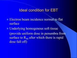
![Selection of energy
Ep0(MeV) = 3.3 x R90 (cm) [R90 exceeds max
depth of PTV]
Ep0(MeV) = 2 x Rp [Rp is the practical range
of electrons ]](https://image.slidesharecdn.com/electronbeamtherapy-210209013724/85/ELECTRON-BEAM-RADIOTHERAPY-30-320.jpg)

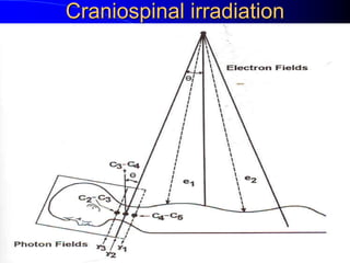
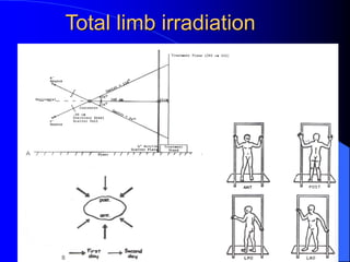


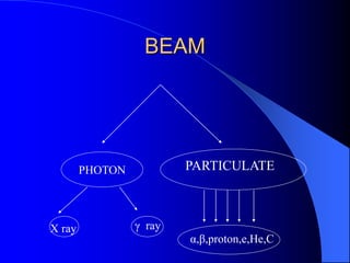
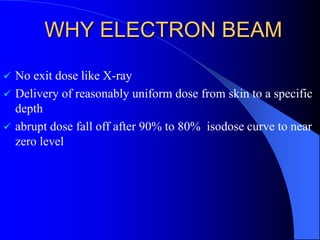
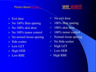
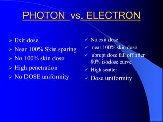
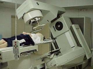
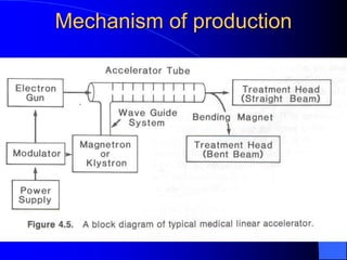
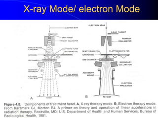
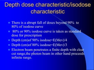
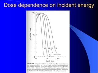
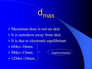
Electron beam therapy is a type of radiation therapy that uses beams of electrons to treat superficial tumors. It has advantages over photon therapy like no exit dose beyond the treatment area and a more abrupt dose fall-off. Electron beams can deliver a reasonably uniform dose from the skin surface to a specific depth before rapidly falling to near zero. This allows for sparing of normal tissues beyond the treatment volume. Electron beam machines like linear accelerators are used to produce high energy electron beams that are then scattered and shaped using scattering foils, applicators, and blocks to conform to the tumor area. Dosimetry is performed to determine the dose distribution and depth-dose characteristics of the electron beams. Electron beam therapy is indicated for diseases affecting the


