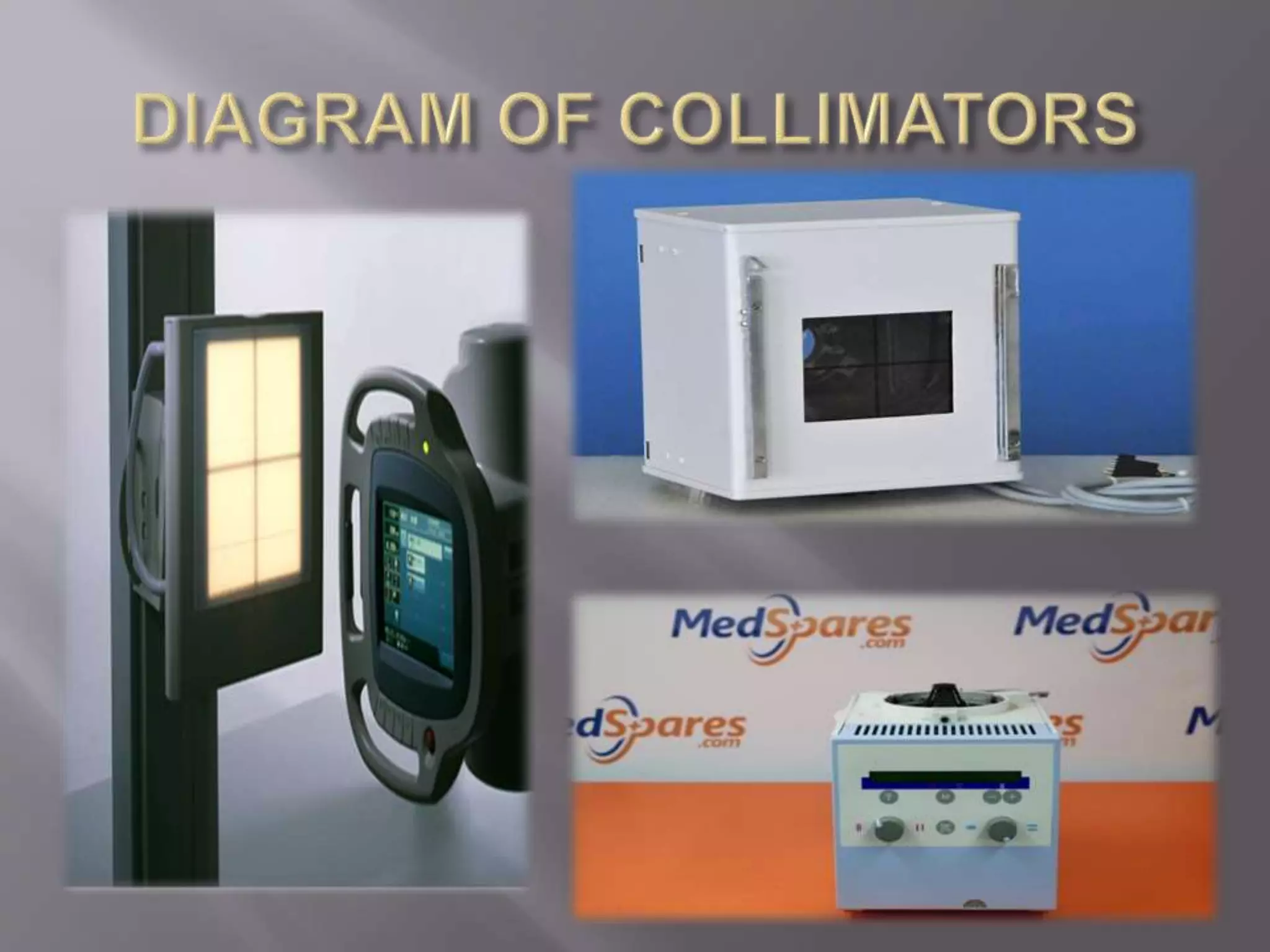
BY:- NITISH RAJPUT
BSc. RADIODIAGNOSIS 2ND YEAR
BATCH-2k16
1- SCATTERED RADIATION
2- BEAM LIMITING DEVICES
3- BEAM CENTERING DEVICES
4- RADIATION GRIDS
5- ASSESMENT OF GRID FUNCTION
 Xray’s belong to a group of radiation known as
the ELECTROMAGNETIC RADIATIONS.
 All the electromagnetic radiations have dual
characteristics.
 WAVE NATURE
 PARTICLE NATURE
 Wave nature can be understood by :- c=
 Particle nature can be understood by :- E=hv
 Scattering is basically of five types:-
 COHERENT
 COMPTON
 PHOTOELECTRIC
 PHOTODISINTEGRATION
 PAIR PRODUCTION
 (of these compton scattering occurs mostly in
diagnostic radiology)
 Basically, when x-rays are absorbed then they
cease to exist but when they are scattered then
they are deflected from there original path and
hence carry no useful information...
 At the end they only add up NOISE (unwanted
densities) to the film.
 The end result is that the radiographic image is
of a poor quality which makes it difficult to
diagnose it. Contrast of the film is also
degraded.
VARIOUS DEVICES TO REDUCE SCATTER:-
 Filters
 Aperture diaphragms
 Cones and cylinders
 Collimators
 Beam centering devices
 Radiographic Grids
 More scatter is created in bone than in soft
tissue.
 When the beam is restricted then less scatter
occurs and hence less of it reaches the film.
 Technical factors may have to be manipulated
to reduce the amount of scatter.
 Filtration is basically a process of shaping the
x-ray beam to increase the amount of useful
photons and decrease the low energy photons
so that we can get an image with better
contrast.
 This also decreases the patient radiation dose
and occupational hazards.
 When exposure is done then both high as well
as low energy x-ray photons are produced.
 When these x-ray photons interact with the
human body, only the high energy photons
penetrate while the low energy photons get
absorbed in the body, hence increasing the
patient radiation dose.
 Filtration basically absorbs the low energy
photons from the beam and hence increases the
image contrast.
 INHERENT FILTRATION(x-ray
tube and its housing).
 ADDED FILTRATION (sheets of
metal placed in the path of beam).
 THE PATIENT.
 The absorption of the low energy x-ray photons by
the x-ray tube components itself is known as the
inherent filtration.
 Glass housing, metal enclosure and the assembly
oil is responsible for inherent filtration.
 Inherent filtration of a tube is measured in
ALUMINIUM EQUIVALENT.
 It is basically the amount of aluminium required to
absorb the same radiation which the tube material
was absorbing.
 Inherent filtration is generally between 0.5-1.00mm
of aluminium equivalent.
 But disadvantage of inherent filtration is that it
causes a significant reduction in the image
contrast.
 At some places where unfiltered x-ray beam is
required, there BERYLLIUM filters are mostly
used.
 Added filtration is a result of any beam
absorber which is placed in the path of the xray
beam, this absorber absorbs the low or high
energy photons.
 Ideally an added filter should absorb all the
low energy photons and let the high energy
photons pass through it.
 But no such material exists.
 SOLUTION- we always use added filters
mostly in a group of Aluminium(13) +
Copper(29).
 They are arranged as the high at. No.(COPPER)
element faces the x-ray tube while the
other(ALUMINIUM) one faces the patient.
 Most of the filtration is done by copper.
 They can't be used separately.
 Patient radiation dose as well as the image
contrast is reduced.
 This combination of two layers of filters is also
known as COMPOUND FILTERS.
 It also increases the tube loading.
 Wedge filters are mostly used at places where the
body part to be radiographed varies greatly in
densities.(thick from one side and thin from
another side)
 Wedge filters are like the shape of a wedge , the
thin part is placed under thick body part while
thick part is placed under thin body part.
 Result is that ,beam attenuation by thick part is
more hence less radiation reaches the part and
beam attenuation by thin part is less hence more
radiation reaches thick part.
 Therefore a radiograph of uniform density is got.
 More will be the thickness of filters ,more will
be the attenuation of x-rays by it.
 In other words:-
 ATTENUATION 0<(directly proportional)
FILTER THICKNESS
 Filters with metals of high atomic number.
 Usually used with x-ray tubes of high capacity
and high speed intensifying screen.
 These filters basically use the K-EDGE
ABSORPTION of the element.
 K-EDGE is basically the
 Beam restricting devices include:-
 APERTURE DIAPHRAGMS.
 CONES AND CYLINDERS.
 COLLIMATORS.
 These are basically the simplest xray beam
restrictors.
 It is made of a sheet of lead which is having a hole
at its centre.
 Its advantage is its simplicity, it can be altered to
any shape or size because lead it is soft.
 Its disadvantage is that it produces a fairly large
PENUMBRA(unexposed area) shadow.
 Penumbra can be reduced by placing the
diaphragm far away from the x-ray tube.
 The centre of the xray field is exposed by the
circular area.
 These restrictors are the shape of cones and
cylinders.
 They reduce the UNEXPOSED AREA at edges
by reducing PENUMBRA.
 The flare of the cone is similar to the geometric
shape of the xray beam, but it is greater than
the flare of the xray beam.
 They are attached to the front of the x-ray tube
and may also be equipped with extensions to
give even better restriction.
 The major disadvantage of these is thtat a
limited shapes and sizes are available even a
large assortment cannot fulfill the demands
and changing them is very inconvenient.
 Collimators are considered the best beam
restrictor devices.
 It is having two advantages:-
 It provides an infinite variety of rectangular
xray fields.
 It also shows the centre point of the xray beam.
 It consists of two sets of SHUTTERS (S1 & S2)
which move in opposite directions to remove
the PENUMBRA produced by each other.
 One set of shutters can be moved without moving
the other shutters which provides a no. of
rectangular shapes.
 A plus sign mounted on the front of the collimator
(made of PLEXIGLASS) helps to identify the centre
of the xray beam.
 Collimators can also measure the film-source
distance with the help of mirrors placed at
45degree inside it.
 Nowadays ( in DR) ,automatic collimators are used
which are known as POSITIVE BEAM LIMITING
DEVICES.
 Alignment of beams have to be checked
periodically
 MATERIAL REQUIRED:-
 Four L shaped wires.
 14*17 inches film.
 Lead foil of R shape.
 Load the film in cassette and place it over the
xray table.
 Now open the collimator shutter to a
convenient size (10*10in.).
 Carefully place four L-shaped wires at the
corners of the light beam.
 Place the lead letter R at the bottom right
corner of the collimated area.
 NOW EXPOSE THE FILM.
 Arrows indicate the area of the LIGHT BEAM
while exposed area indicates the area of XRAY
BEAM.
 Grids were invented by DR. GUSTAVE
BUCKY in 1913.
 Grids are used to decrease the patient radiation
dose and the scattered radiation.
 Grids basically consists of LEAD
INTERSPACING (interspace is made up of
ORGANIC MATERIAL OR ALUMINIUM)
which is aligned with the geometry of xray
beam of a particular tube.
 Grid ratio is defined as the ratio of the height of
the lead strips to the distance between the lead
strips.
 Grid ratio is always expressed as e.g. 8:1(where
8 is the actual ratio and the second no. is
always one).
 In radiology ,grids of ratio between 4:1 to 16:1
are generally used.
 Usually the thickness of lead strips is about
o.o5mm.
 Basically there are two types of grid pattern :-
 1-LINEAR GRID
 2-CROSSED GRID
 LINEAR GRID is a grid in which the lead strips
are placed parallel to each other.
 Its advantage is that when using linear grid ,then
we can angle the tube also.
 CROSSED GRID is formed when two linear grids
are overlapped with each other. It cannot be used
with oblique techniques.
 A focused grid is a grid which is made up of
lead strips which are angled slightly so that
they focus in space.
 Distance b/w the FOCUS and the lead strips is
known as the FOCAL LENGTH of the grid.
 There focus is also of two types.:-
 1-convergent line focus.
 2-convergent point focus.
 Focal ranges of the grid are indicated on the
top of the grids y manufacturers.
 It is basically the no. of lead strips present per
inch of the grid.
 Its formula is :- 25.4
D+d
Where:- D=thickness of interspaces
d=thickness of lead strips
and 25.4 is the no. of mm in 1 inch
 There are three tests which are used evaluate
the grid performance.
 CONTRAST IMPROVEMENT FACTOR.
 PRIMARY TRANSMISSION.
 BUCKY FACTOR.
 Contrast improvement factor is the ratio of the
contrast with grid to without the grid (K).
 Its formula:- contrast with GRID
 contrast without GRID
 This is the ultimate test for grids performance
because it measures the ability of the grid to
improve its contrast.
 It is the percentage of the primary radiation
transmitted through the grid (ideally it should
be 100%).
 It requires a special equipment to measure the
primary transmission of the grid.
 Typical value of pt. is b/w 55% to 75%.
 Theoretical calculation > actual calculation.
 PRIMARY TRANSMISSION =intensitywitgrid*
intensity without grid
 It is the ratio of the incident radiation falling on
the grid to the transmitted radiation passing
through the grid.
 It is a practical determination because it
indicates how much we should increase or
decrease the factors when doing xrays with or
without grid.
 BUCKY FACTOR(B)=incident radiation
 transmitted radiation
The control of scattered radiation

The control of scattered radiation

  • 1.
    BY:- NITISH RAJPUT BSc.RADIODIAGNOSIS 2ND YEAR BATCH-2k16
  • 2.
    1- SCATTERED RADIATION 2-BEAM LIMITING DEVICES 3- BEAM CENTERING DEVICES 4- RADIATION GRIDS 5- ASSESMENT OF GRID FUNCTION
  • 3.
     Xray’s belongto a group of radiation known as the ELECTROMAGNETIC RADIATIONS.  All the electromagnetic radiations have dual characteristics.  WAVE NATURE  PARTICLE NATURE  Wave nature can be understood by :- c=  Particle nature can be understood by :- E=hv
  • 6.
     Scattering isbasically of five types:-  COHERENT  COMPTON  PHOTOELECTRIC  PHOTODISINTEGRATION  PAIR PRODUCTION  (of these compton scattering occurs mostly in diagnostic radiology)
  • 7.
     Basically, whenx-rays are absorbed then they cease to exist but when they are scattered then they are deflected from there original path and hence carry no useful information...  At the end they only add up NOISE (unwanted densities) to the film.  The end result is that the radiographic image is of a poor quality which makes it difficult to diagnose it. Contrast of the film is also degraded.
  • 9.
    VARIOUS DEVICES TOREDUCE SCATTER:-  Filters  Aperture diaphragms  Cones and cylinders  Collimators  Beam centering devices  Radiographic Grids
  • 10.
     More scatteris created in bone than in soft tissue.  When the beam is restricted then less scatter occurs and hence less of it reaches the film.  Technical factors may have to be manipulated to reduce the amount of scatter.
  • 11.
     Filtration isbasically a process of shaping the x-ray beam to increase the amount of useful photons and decrease the low energy photons so that we can get an image with better contrast.  This also decreases the patient radiation dose and occupational hazards.
  • 12.
     When exposureis done then both high as well as low energy x-ray photons are produced.  When these x-ray photons interact with the human body, only the high energy photons penetrate while the low energy photons get absorbed in the body, hence increasing the patient radiation dose.  Filtration basically absorbs the low energy photons from the beam and hence increases the image contrast.
  • 14.
     INHERENT FILTRATION(x-ray tubeand its housing).  ADDED FILTRATION (sheets of metal placed in the path of beam).  THE PATIENT.
  • 15.
     The absorptionof the low energy x-ray photons by the x-ray tube components itself is known as the inherent filtration.  Glass housing, metal enclosure and the assembly oil is responsible for inherent filtration.  Inherent filtration of a tube is measured in ALUMINIUM EQUIVALENT.  It is basically the amount of aluminium required to absorb the same radiation which the tube material was absorbing.  Inherent filtration is generally between 0.5-1.00mm of aluminium equivalent.
  • 16.
     But disadvantageof inherent filtration is that it causes a significant reduction in the image contrast.  At some places where unfiltered x-ray beam is required, there BERYLLIUM filters are mostly used.
  • 18.
     Added filtrationis a result of any beam absorber which is placed in the path of the xray beam, this absorber absorbs the low or high energy photons.  Ideally an added filter should absorb all the low energy photons and let the high energy photons pass through it.  But no such material exists.  SOLUTION- we always use added filters mostly in a group of Aluminium(13) + Copper(29).
  • 19.
     They arearranged as the high at. No.(COPPER) element faces the x-ray tube while the other(ALUMINIUM) one faces the patient.  Most of the filtration is done by copper.  They can't be used separately.  Patient radiation dose as well as the image contrast is reduced.  This combination of two layers of filters is also known as COMPOUND FILTERS.  It also increases the tube loading.
  • 21.
     Wedge filtersare mostly used at places where the body part to be radiographed varies greatly in densities.(thick from one side and thin from another side)  Wedge filters are like the shape of a wedge , the thin part is placed under thick body part while thick part is placed under thin body part.  Result is that ,beam attenuation by thick part is more hence less radiation reaches the part and beam attenuation by thin part is less hence more radiation reaches thick part.  Therefore a radiograph of uniform density is got.
  • 23.
     More willbe the thickness of filters ,more will be the attenuation of x-rays by it.  In other words:-  ATTENUATION 0<(directly proportional) FILTER THICKNESS
  • 24.
     Filters withmetals of high atomic number.  Usually used with x-ray tubes of high capacity and high speed intensifying screen.  These filters basically use the K-EDGE ABSORPTION of the element.  K-EDGE is basically the
  • 25.
     Beam restrictingdevices include:-  APERTURE DIAPHRAGMS.  CONES AND CYLINDERS.  COLLIMATORS.
  • 26.
     These arebasically the simplest xray beam restrictors.  It is made of a sheet of lead which is having a hole at its centre.  Its advantage is its simplicity, it can be altered to any shape or size because lead it is soft.  Its disadvantage is that it produces a fairly large PENUMBRA(unexposed area) shadow.  Penumbra can be reduced by placing the diaphragm far away from the x-ray tube.  The centre of the xray field is exposed by the circular area.
  • 28.
     These restrictorsare the shape of cones and cylinders.  They reduce the UNEXPOSED AREA at edges by reducing PENUMBRA.  The flare of the cone is similar to the geometric shape of the xray beam, but it is greater than the flare of the xray beam.  They are attached to the front of the x-ray tube and may also be equipped with extensions to give even better restriction.
  • 29.
     The majordisadvantage of these is thtat a limited shapes and sizes are available even a large assortment cannot fulfill the demands and changing them is very inconvenient.
  • 31.
     Collimators areconsidered the best beam restrictor devices.  It is having two advantages:-  It provides an infinite variety of rectangular xray fields.  It also shows the centre point of the xray beam.  It consists of two sets of SHUTTERS (S1 & S2) which move in opposite directions to remove the PENUMBRA produced by each other.
  • 32.
     One setof shutters can be moved without moving the other shutters which provides a no. of rectangular shapes.  A plus sign mounted on the front of the collimator (made of PLEXIGLASS) helps to identify the centre of the xray beam.  Collimators can also measure the film-source distance with the help of mirrors placed at 45degree inside it.  Nowadays ( in DR) ,automatic collimators are used which are known as POSITIVE BEAM LIMITING DEVICES.
  • 34.
     Alignment ofbeams have to be checked periodically  MATERIAL REQUIRED:-  Four L shaped wires.  14*17 inches film.  Lead foil of R shape.
  • 35.
     Load thefilm in cassette and place it over the xray table.  Now open the collimator shutter to a convenient size (10*10in.).  Carefully place four L-shaped wires at the corners of the light beam.  Place the lead letter R at the bottom right corner of the collimated area.  NOW EXPOSE THE FILM.
  • 37.
     Arrows indicatethe area of the LIGHT BEAM while exposed area indicates the area of XRAY BEAM.
  • 38.
     Grids wereinvented by DR. GUSTAVE BUCKY in 1913.  Grids are used to decrease the patient radiation dose and the scattered radiation.  Grids basically consists of LEAD INTERSPACING (interspace is made up of ORGANIC MATERIAL OR ALUMINIUM) which is aligned with the geometry of xray beam of a particular tube.
  • 40.
     Grid ratiois defined as the ratio of the height of the lead strips to the distance between the lead strips.  Grid ratio is always expressed as e.g. 8:1(where 8 is the actual ratio and the second no. is always one).  In radiology ,grids of ratio between 4:1 to 16:1 are generally used.  Usually the thickness of lead strips is about o.o5mm.
  • 41.
     Basically thereare two types of grid pattern :-  1-LINEAR GRID  2-CROSSED GRID  LINEAR GRID is a grid in which the lead strips are placed parallel to each other.  Its advantage is that when using linear grid ,then we can angle the tube also.  CROSSED GRID is formed when two linear grids are overlapped with each other. It cannot be used with oblique techniques.
  • 43.
     A focusedgrid is a grid which is made up of lead strips which are angled slightly so that they focus in space.  Distance b/w the FOCUS and the lead strips is known as the FOCAL LENGTH of the grid.  There focus is also of two types.:-  1-convergent line focus.  2-convergent point focus.  Focal ranges of the grid are indicated on the top of the grids y manufacturers.
  • 45.
     It isbasically the no. of lead strips present per inch of the grid.  Its formula is :- 25.4 D+d Where:- D=thickness of interspaces d=thickness of lead strips and 25.4 is the no. of mm in 1 inch
  • 46.
     There arethree tests which are used evaluate the grid performance.  CONTRAST IMPROVEMENT FACTOR.  PRIMARY TRANSMISSION.  BUCKY FACTOR.
  • 47.
     Contrast improvementfactor is the ratio of the contrast with grid to without the grid (K).  Its formula:- contrast with GRID  contrast without GRID  This is the ultimate test for grids performance because it measures the ability of the grid to improve its contrast.
  • 48.
     It isthe percentage of the primary radiation transmitted through the grid (ideally it should be 100%).  It requires a special equipment to measure the primary transmission of the grid.
  • 49.
     Typical valueof pt. is b/w 55% to 75%.  Theoretical calculation > actual calculation.  PRIMARY TRANSMISSION =intensitywitgrid* intensity without grid
  • 51.
     It isthe ratio of the incident radiation falling on the grid to the transmitted radiation passing through the grid.  It is a practical determination because it indicates how much we should increase or decrease the factors when doing xrays with or without grid.  BUCKY FACTOR(B)=incident radiation  transmitted radiation