Downloaded 175 times
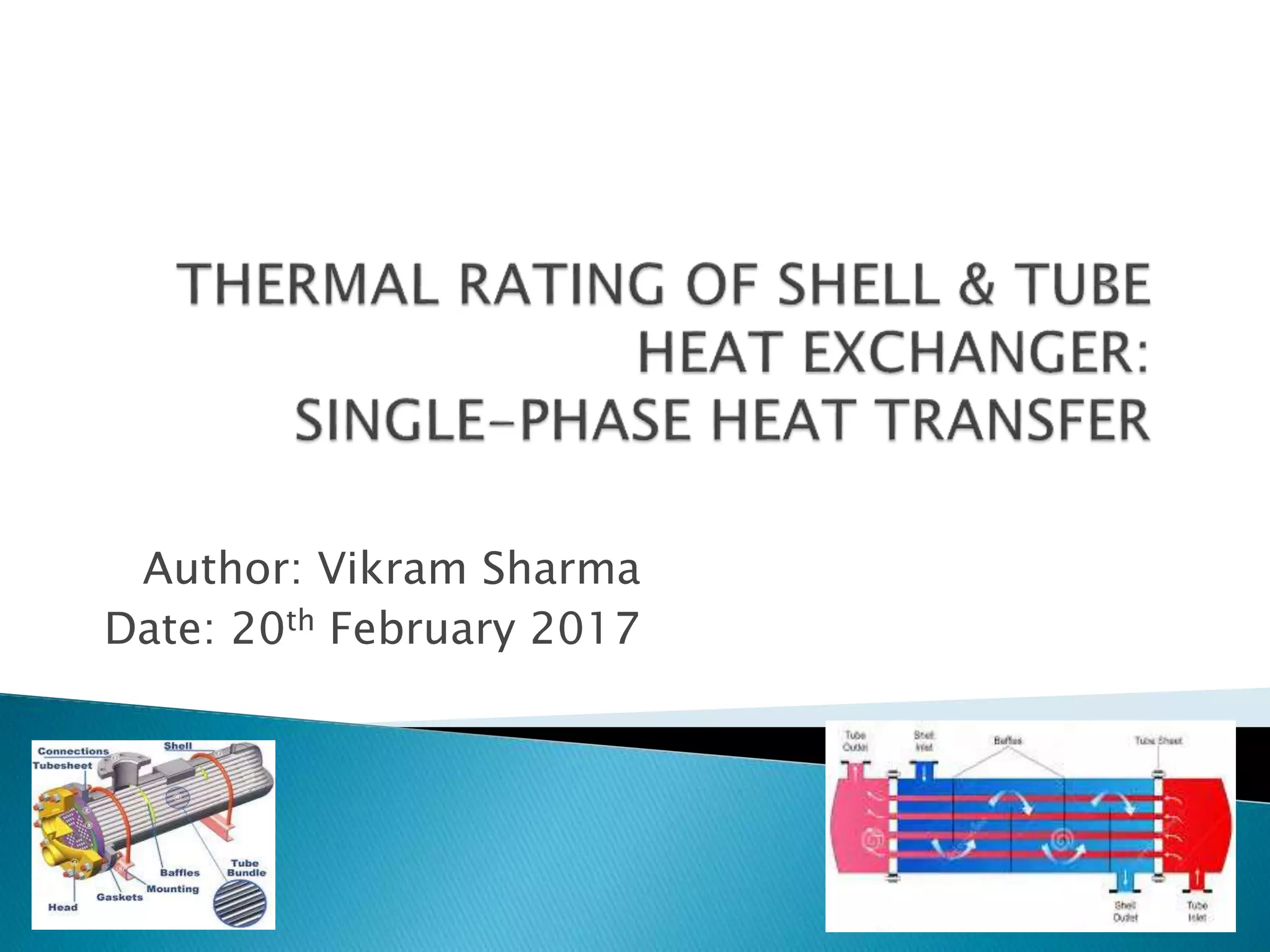
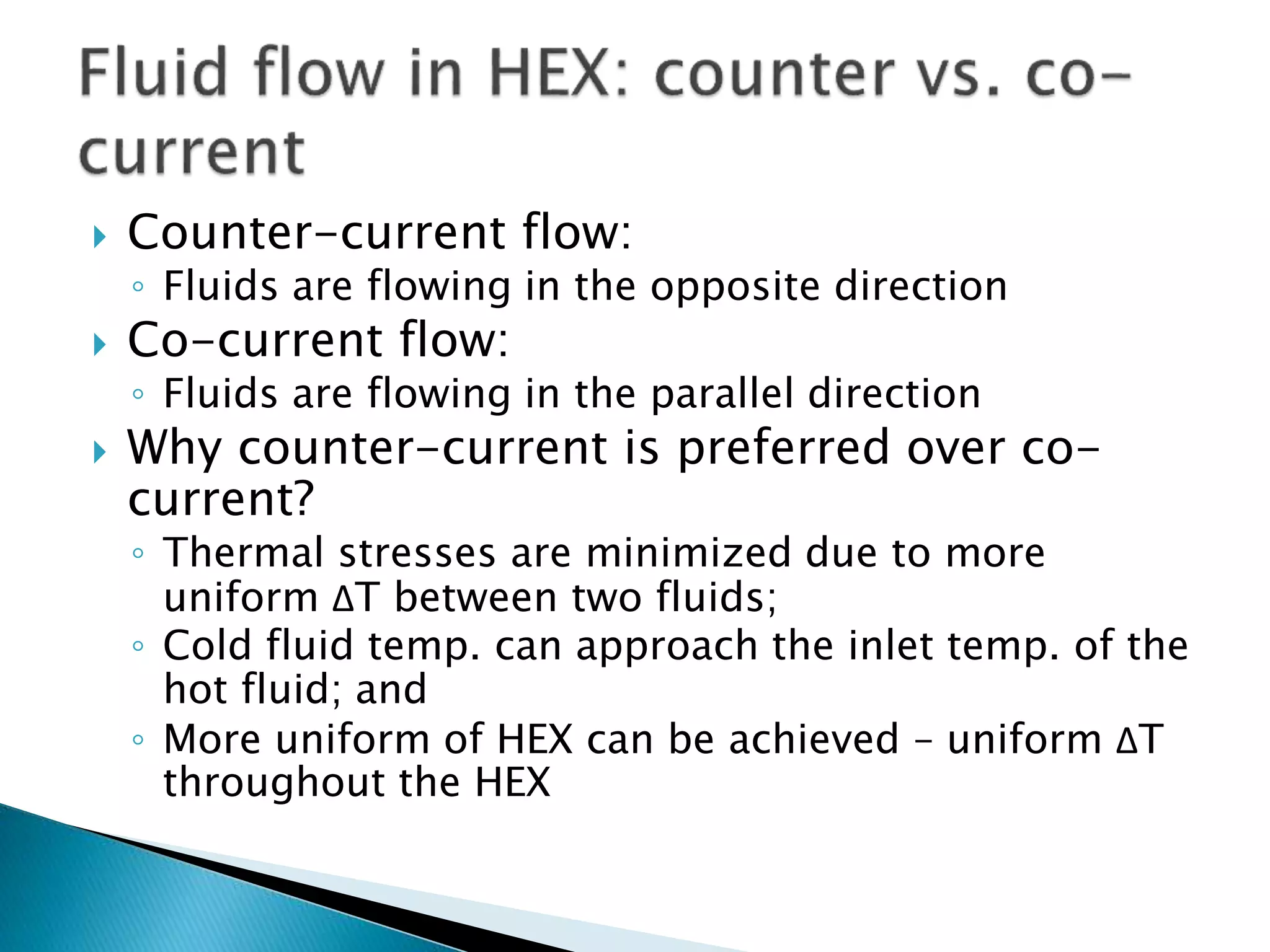
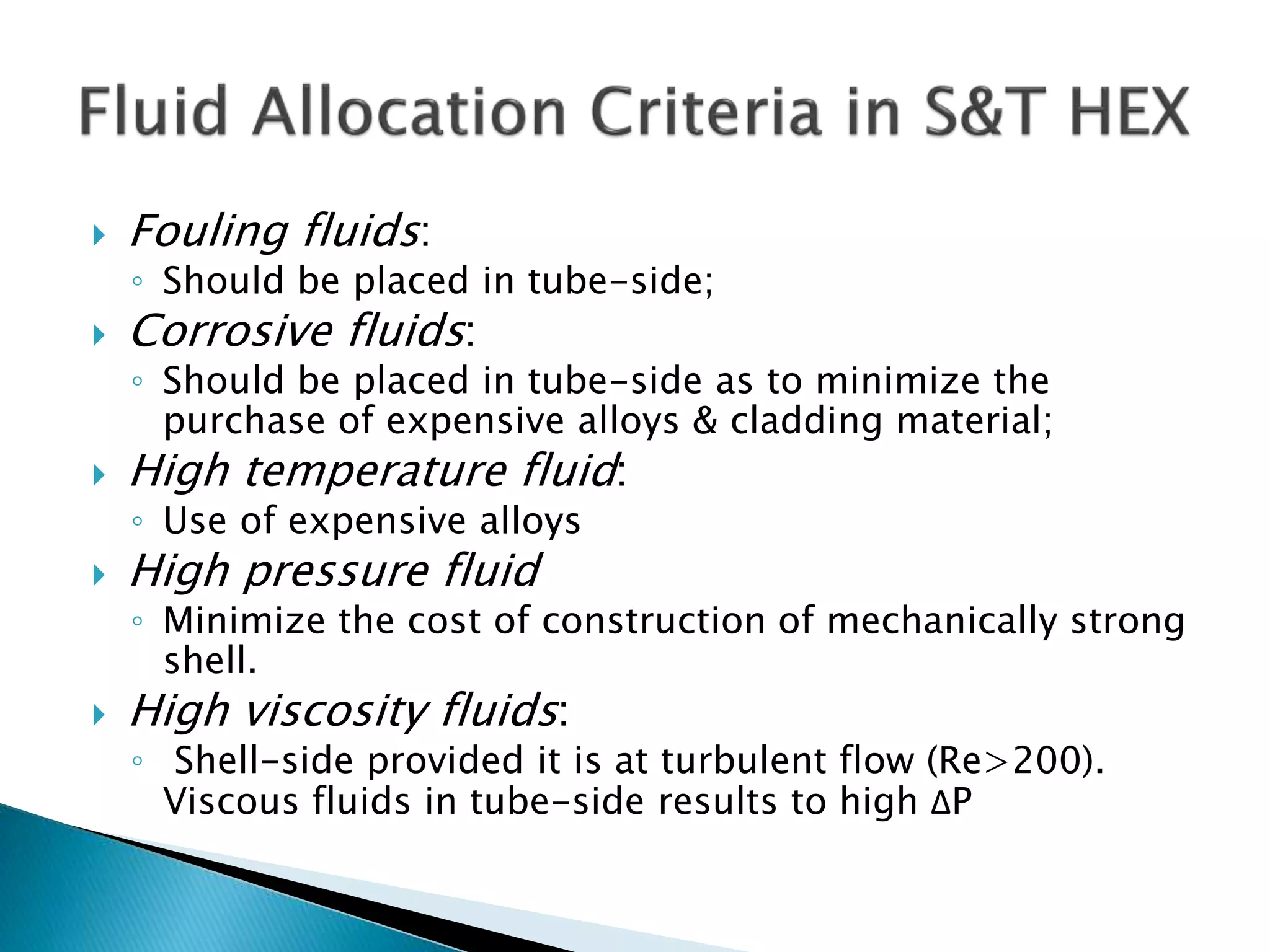
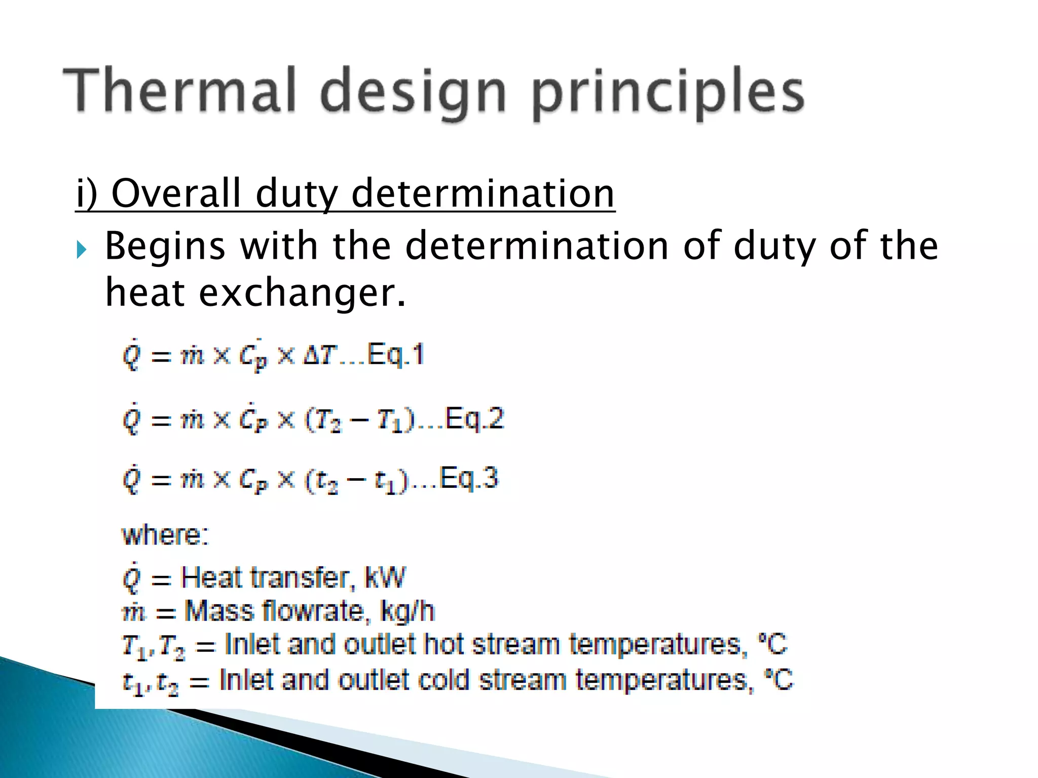
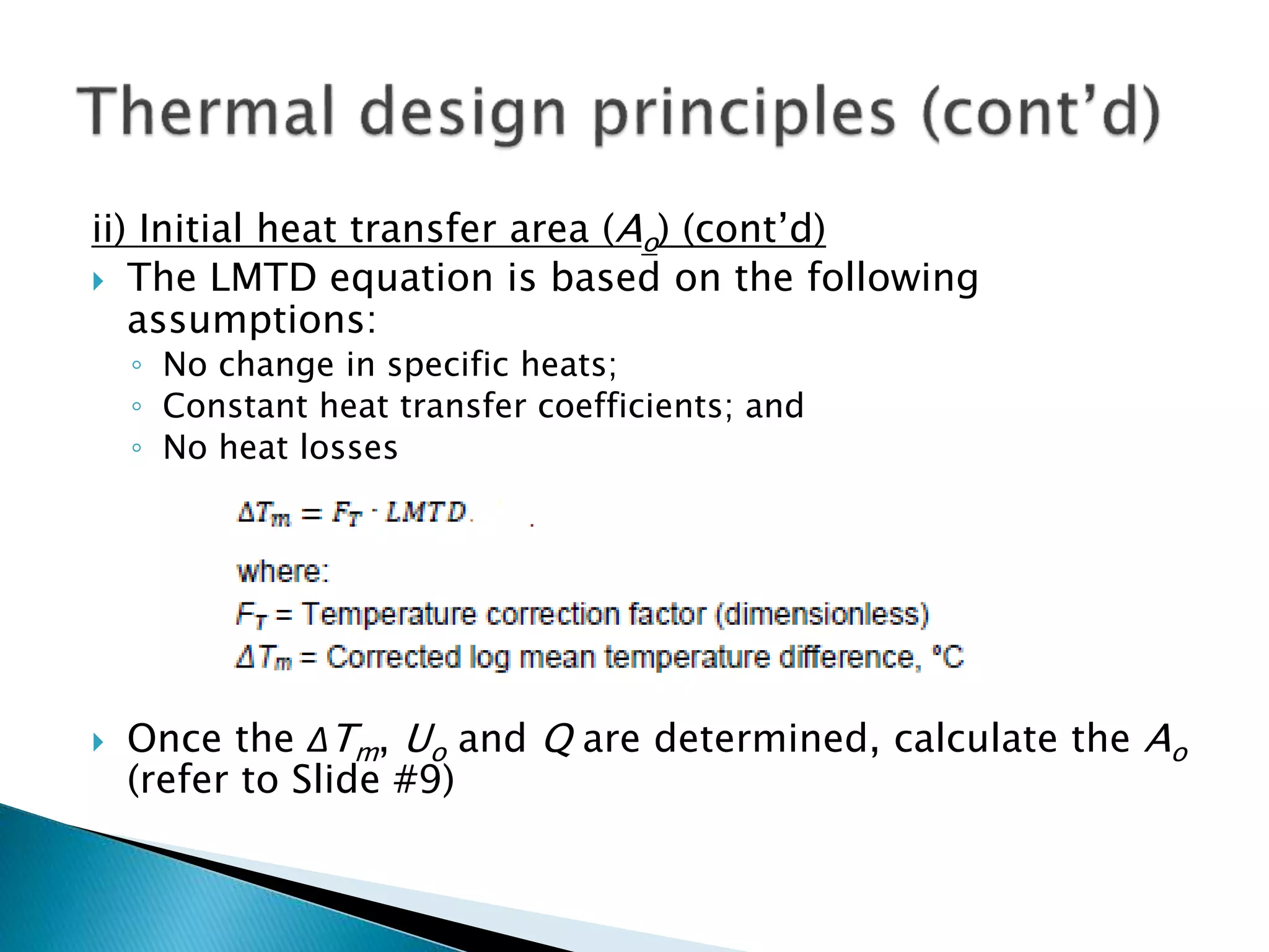
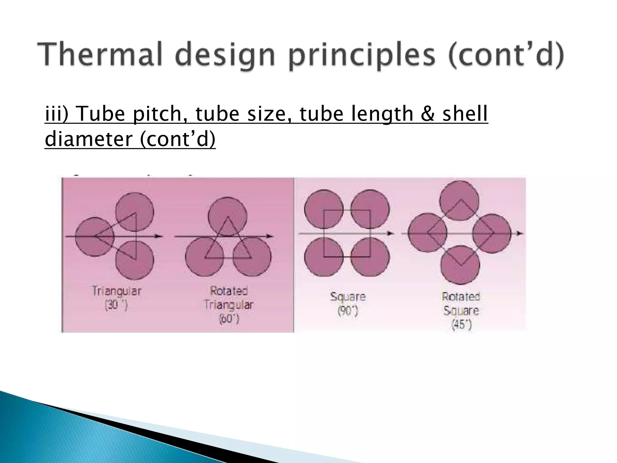

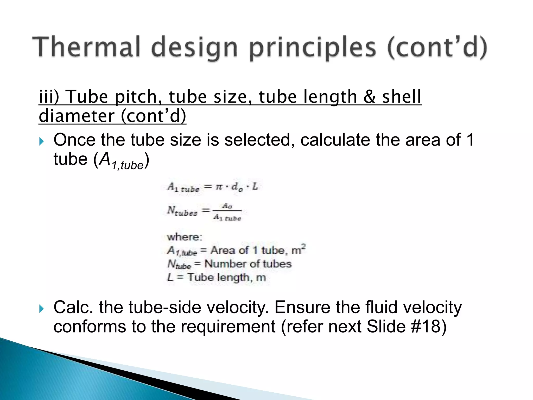
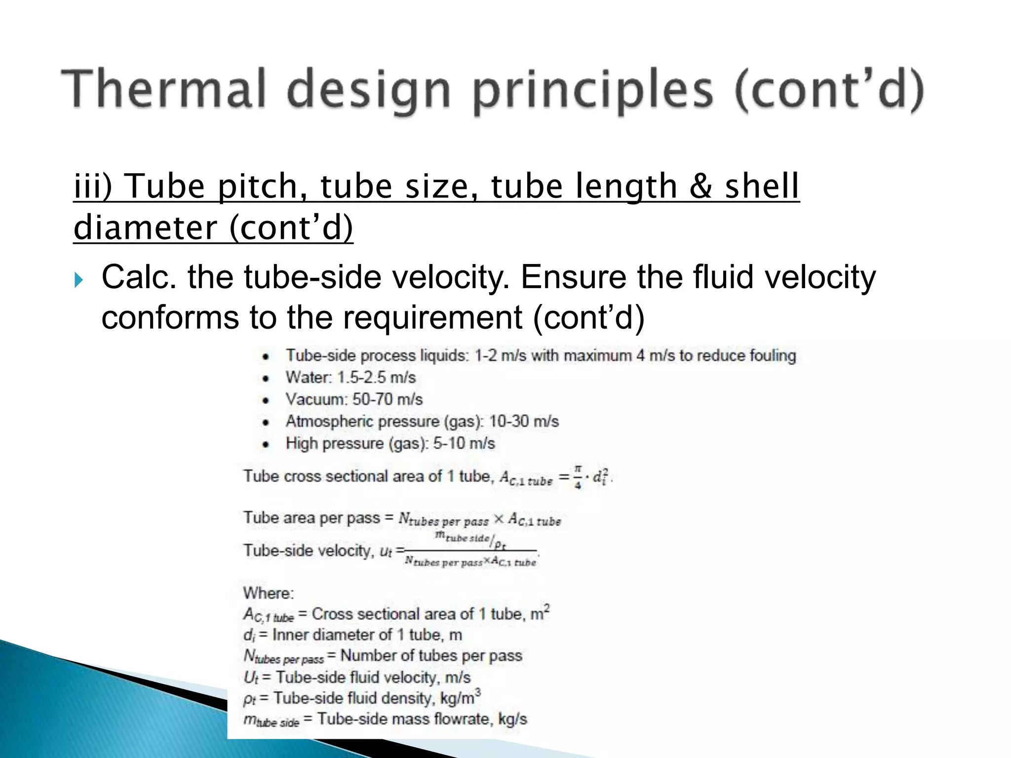
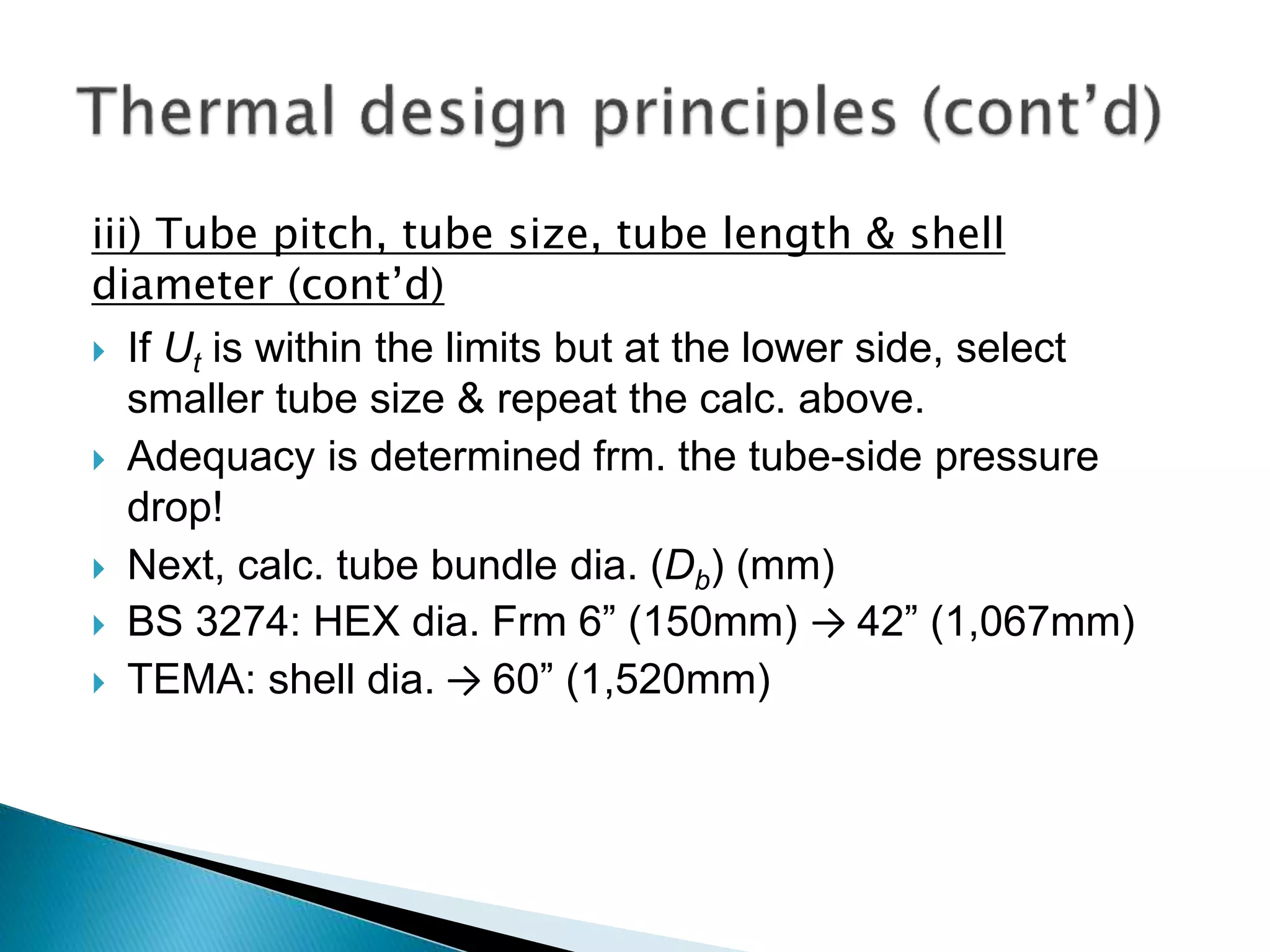
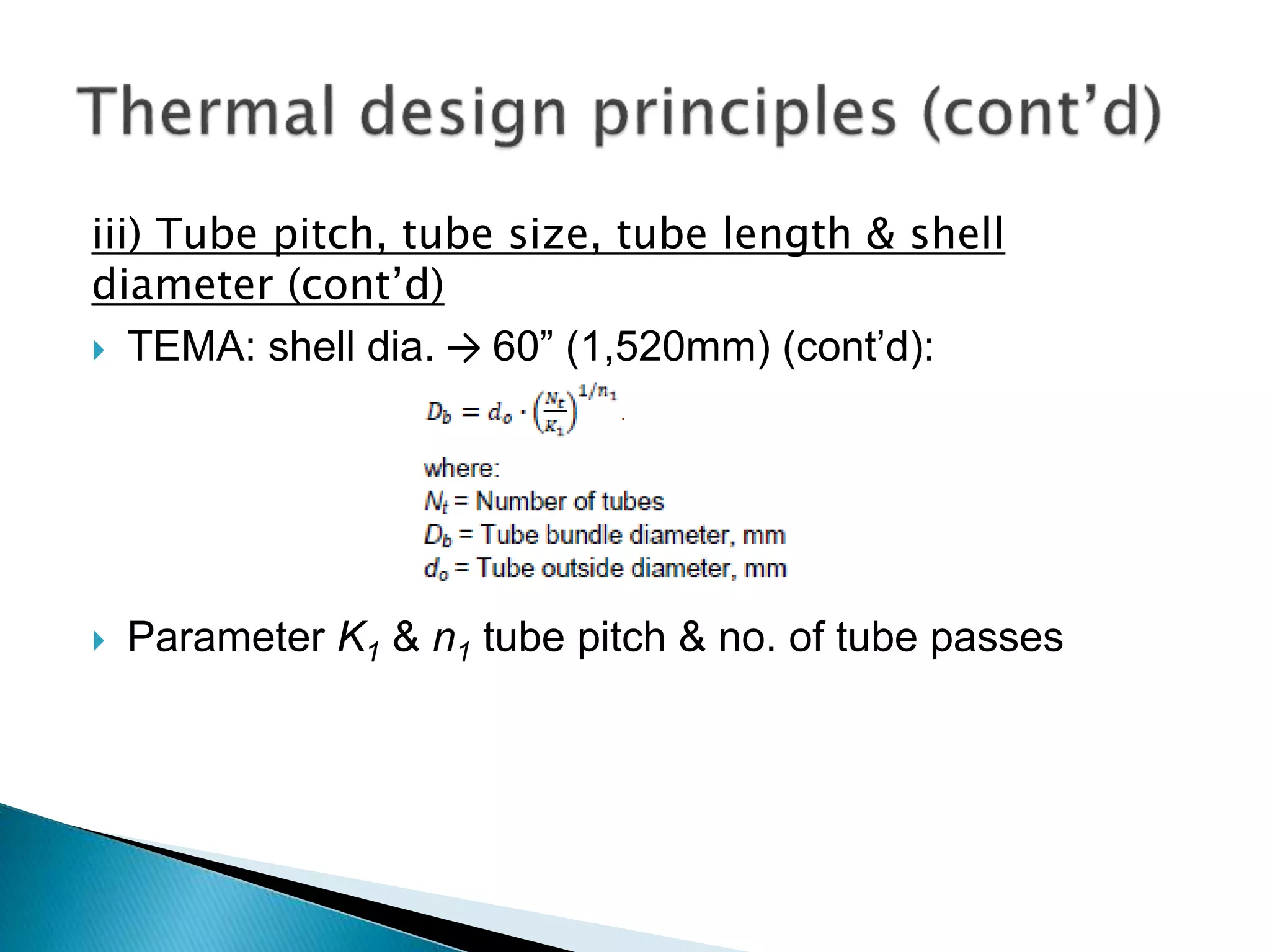
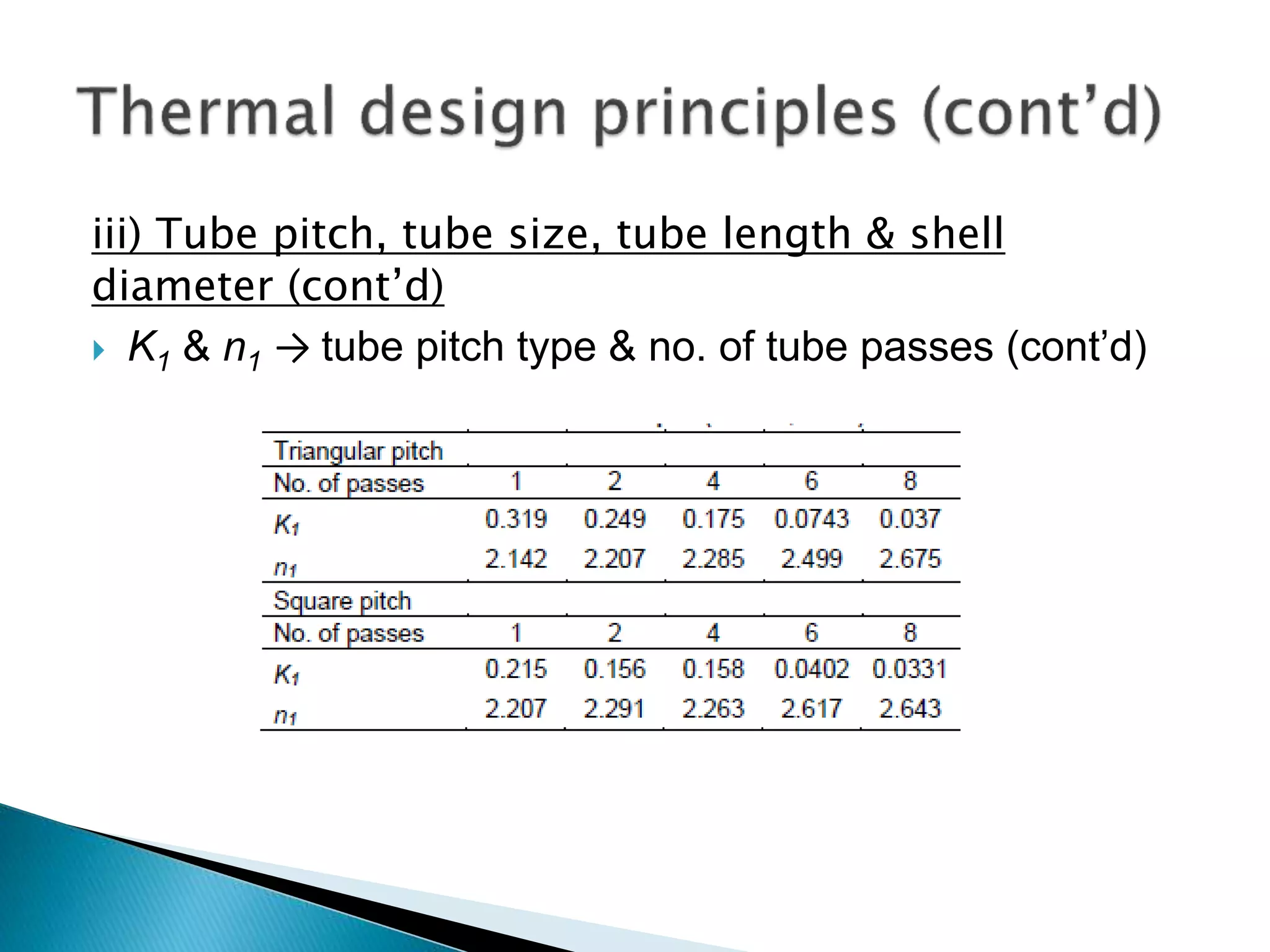
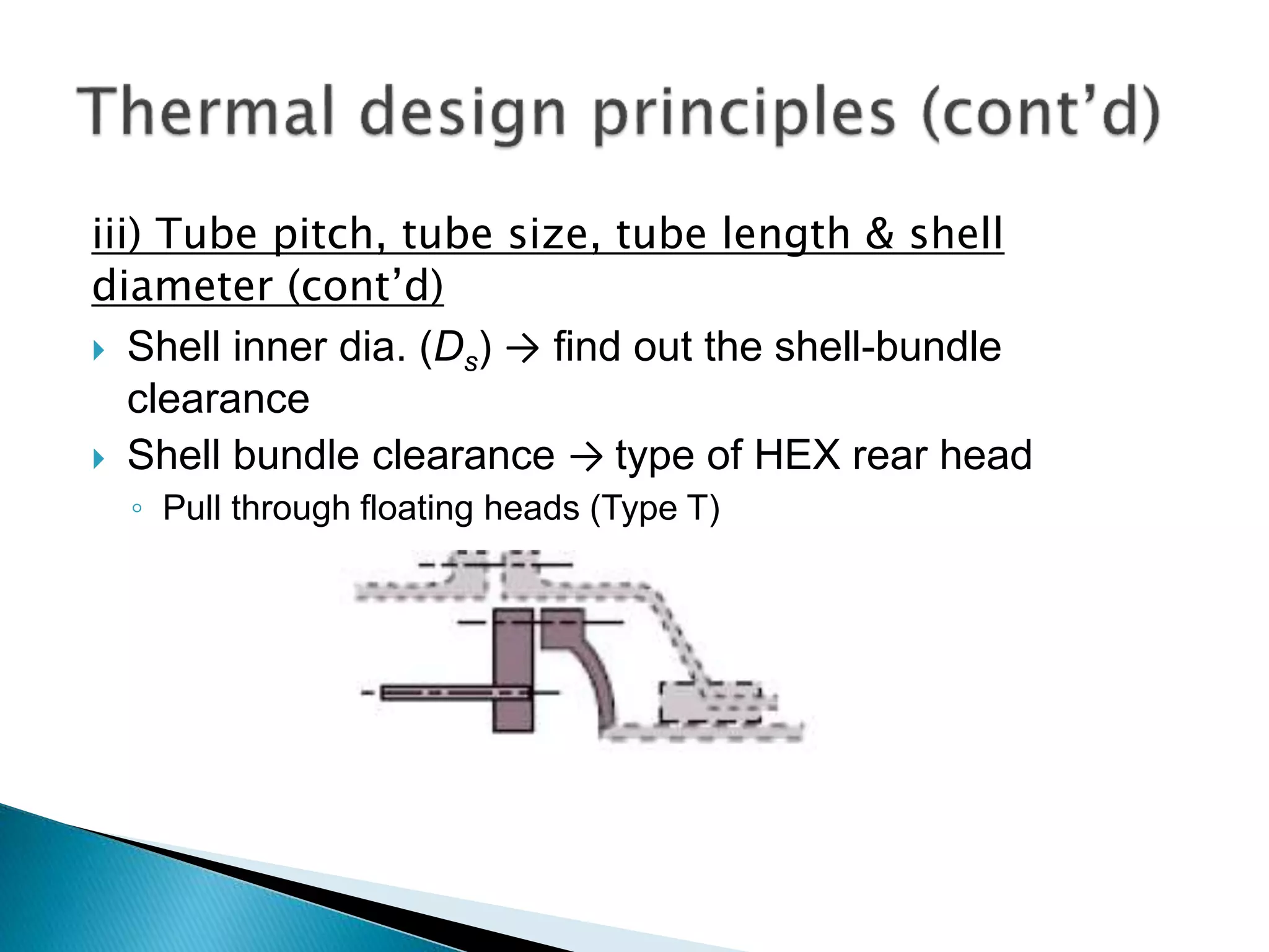
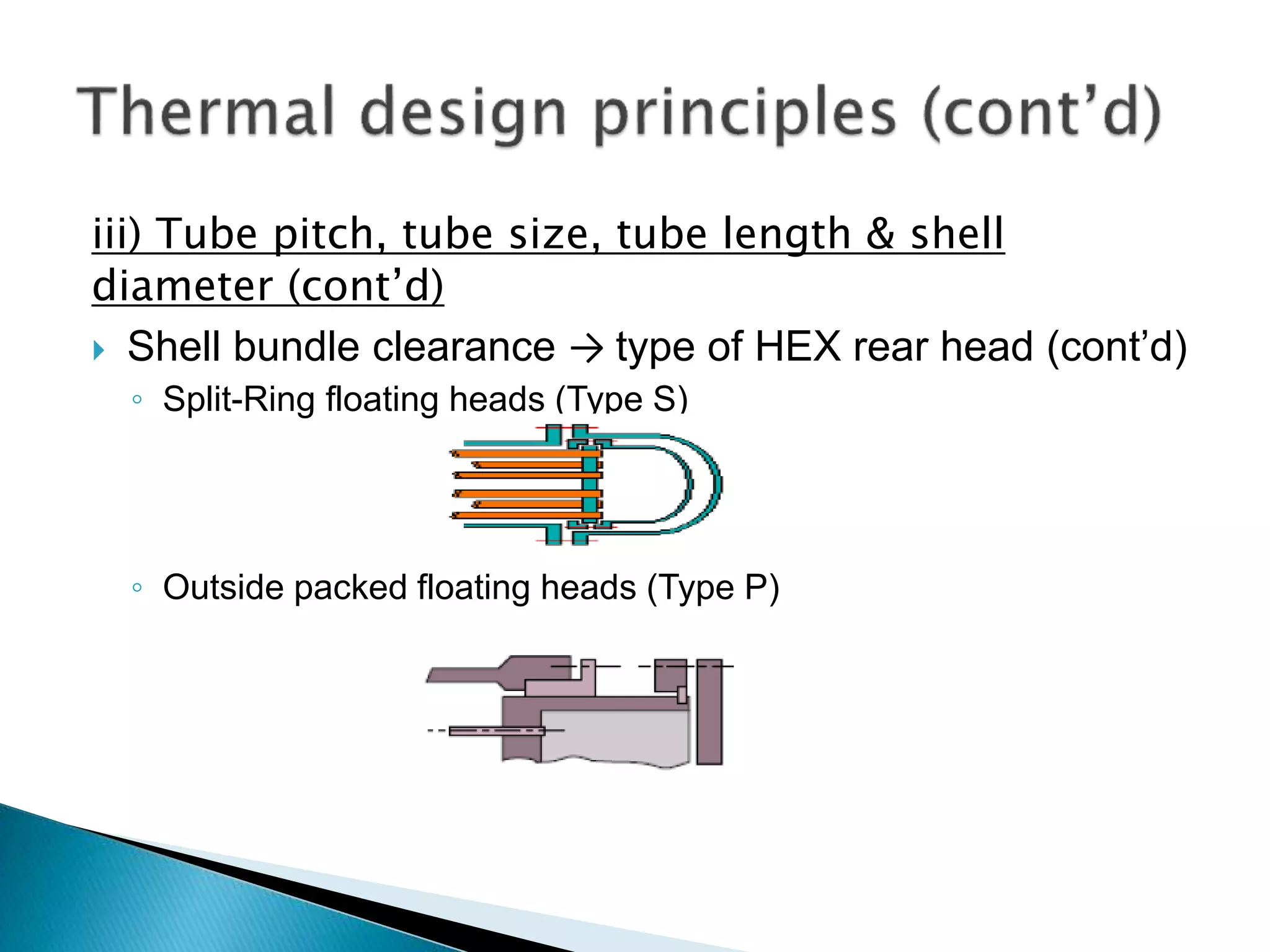
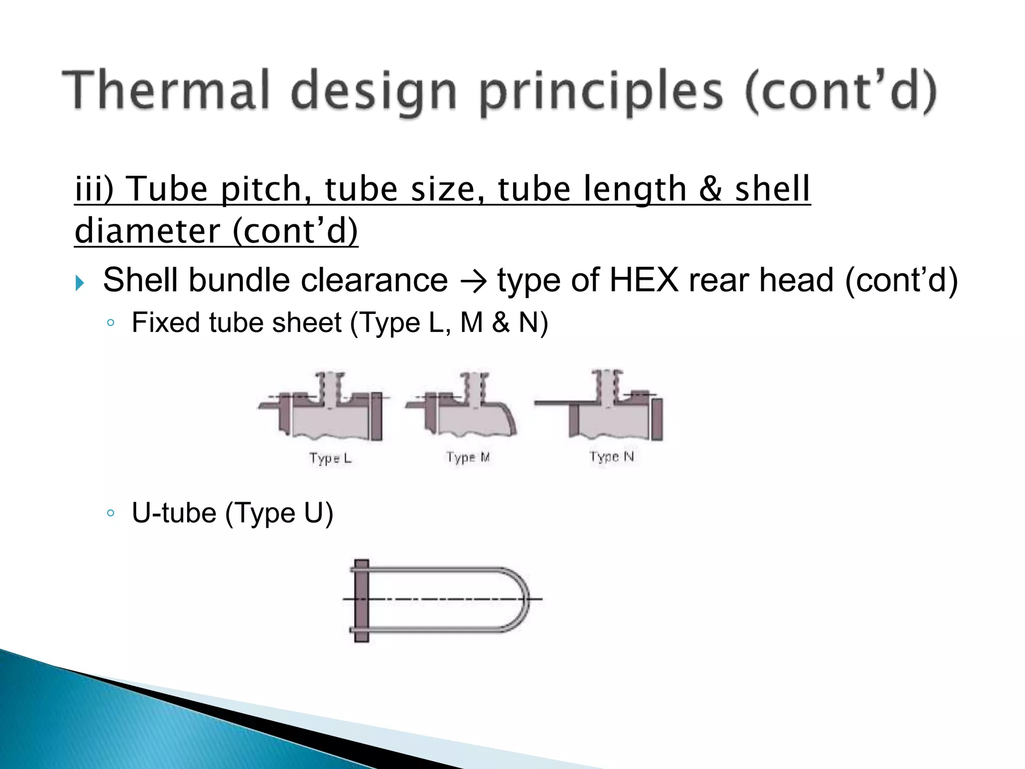
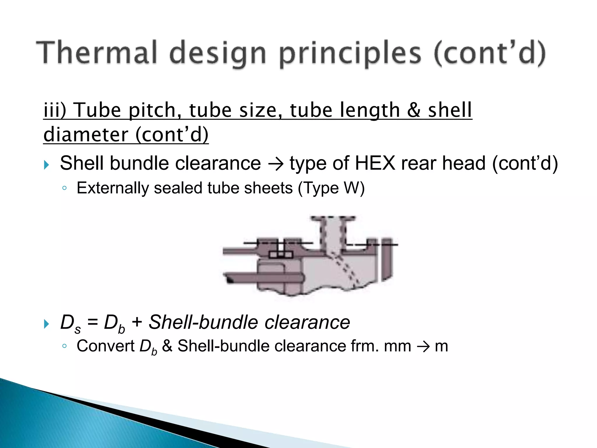
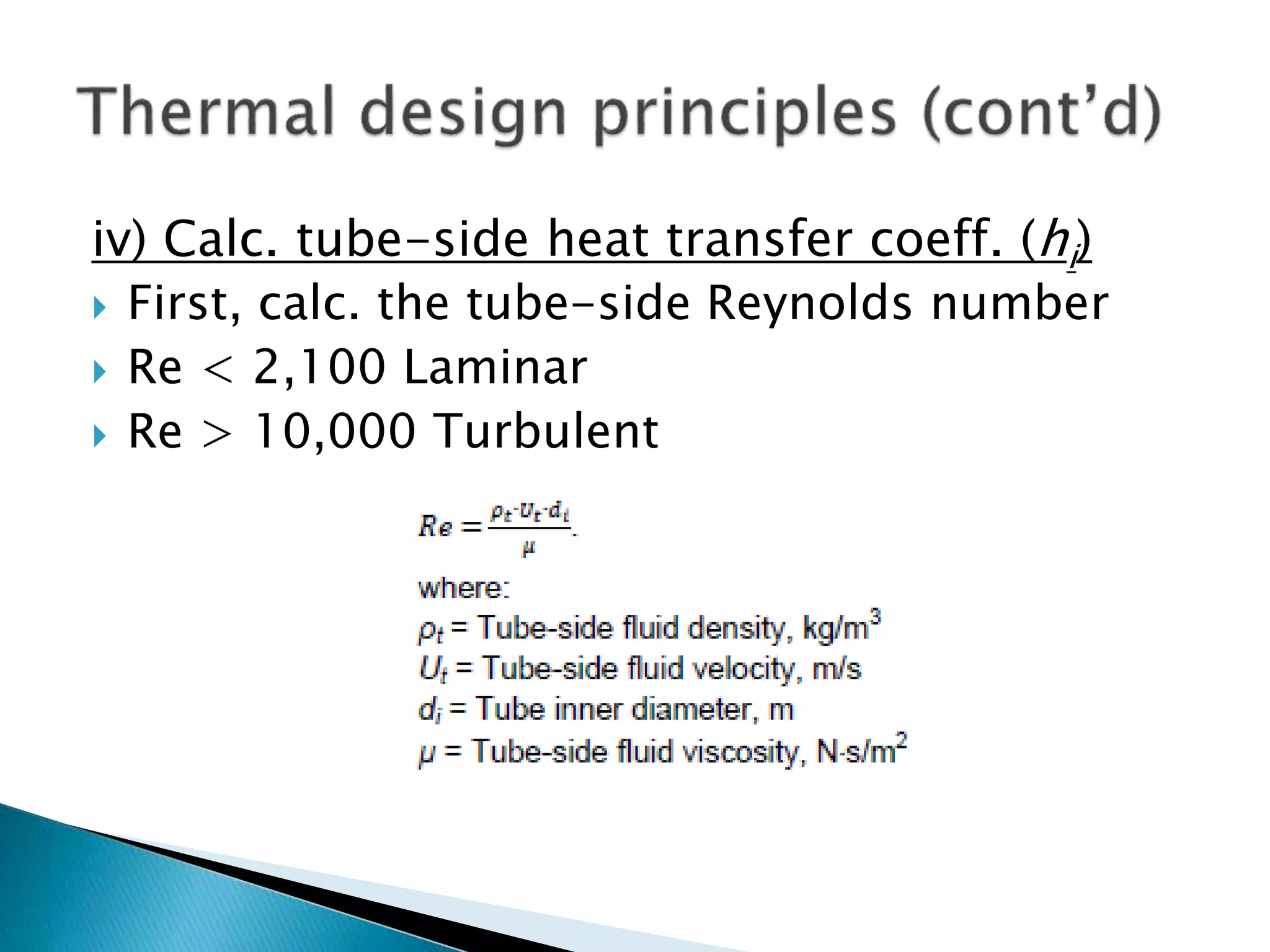
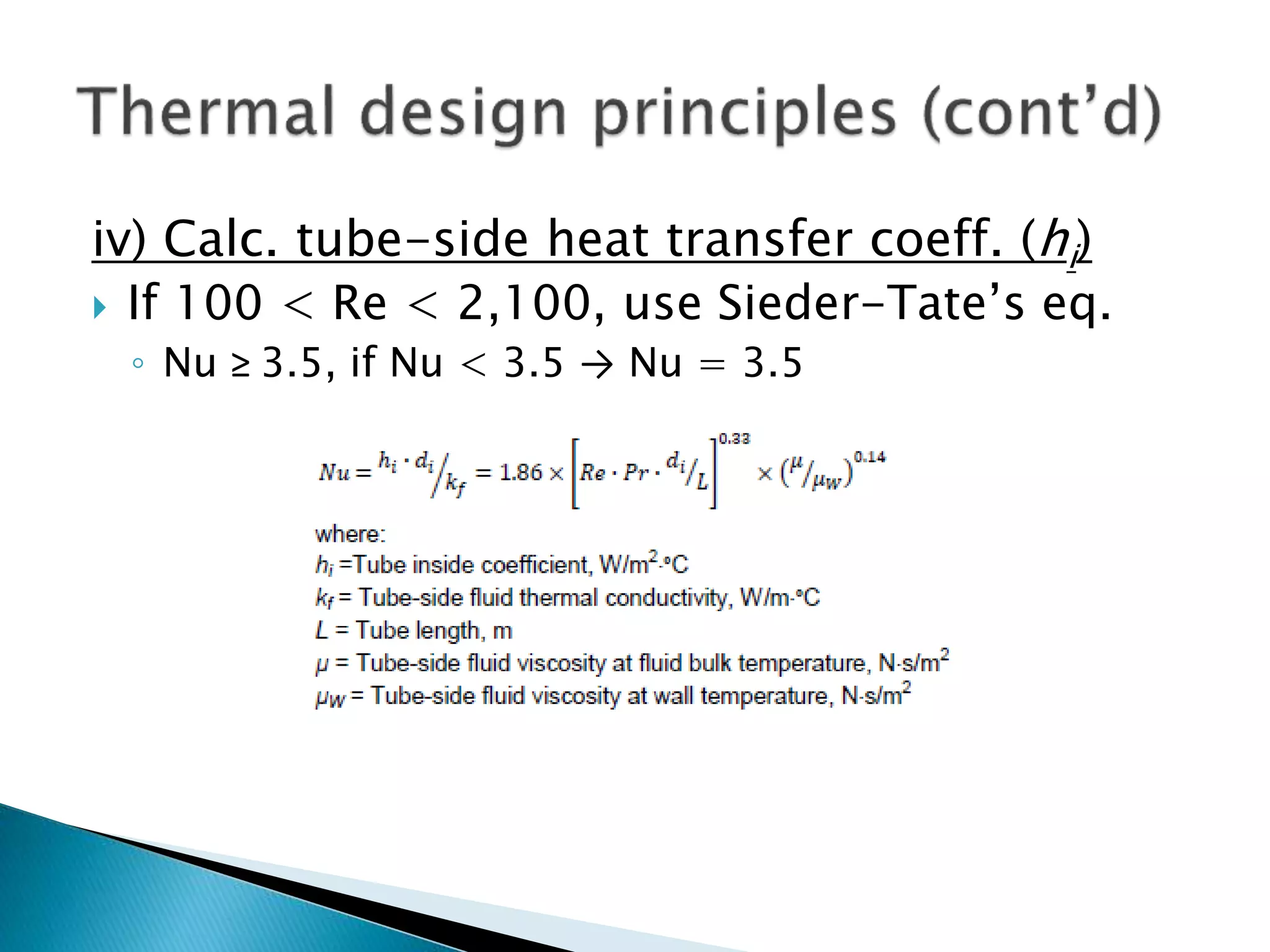
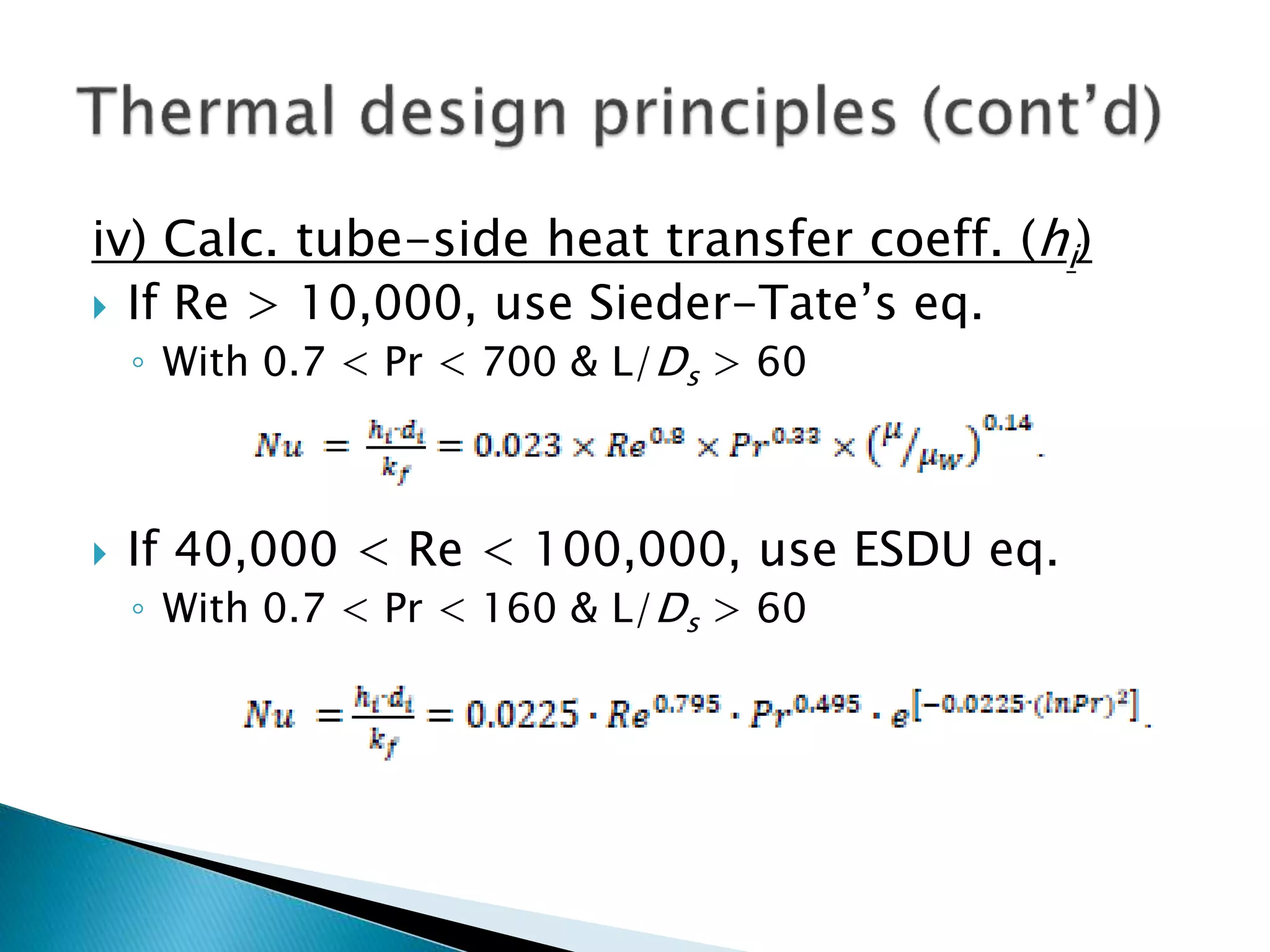
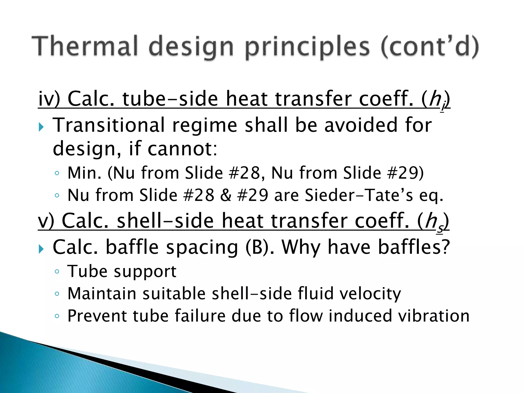
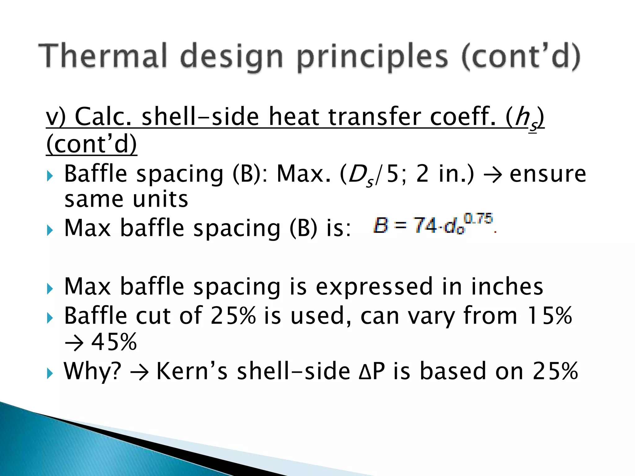
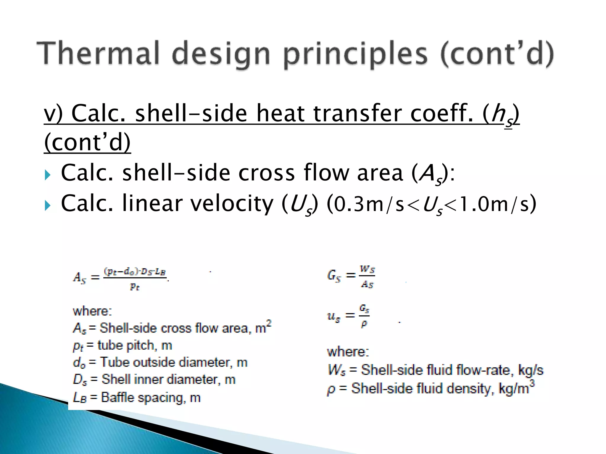
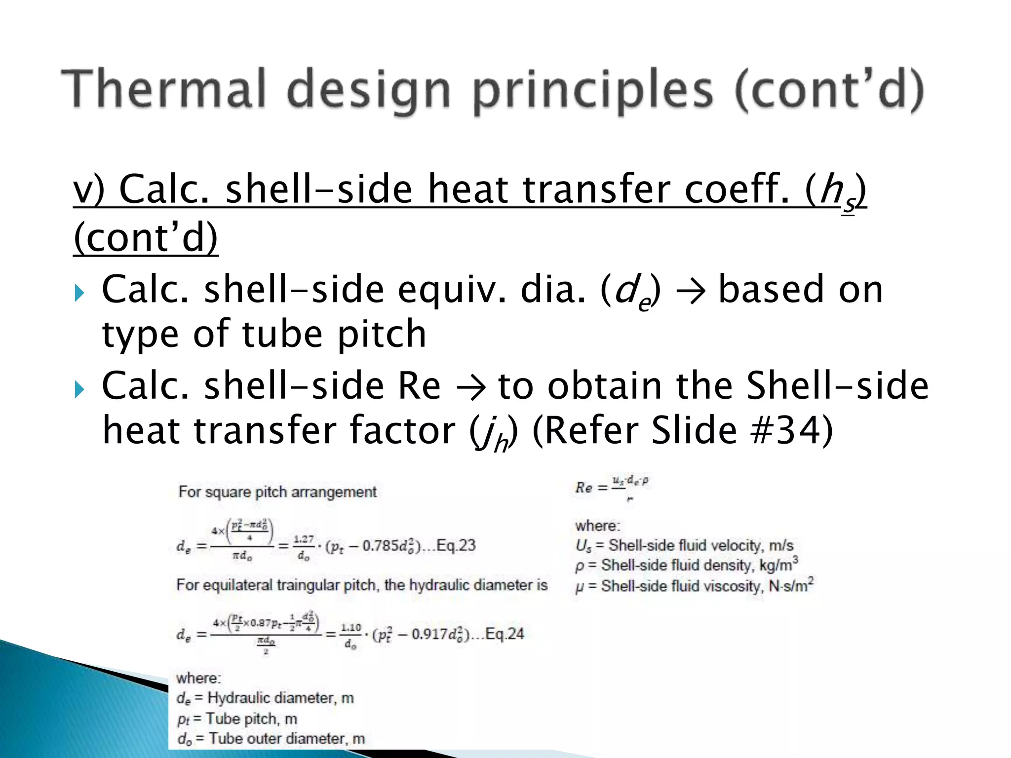
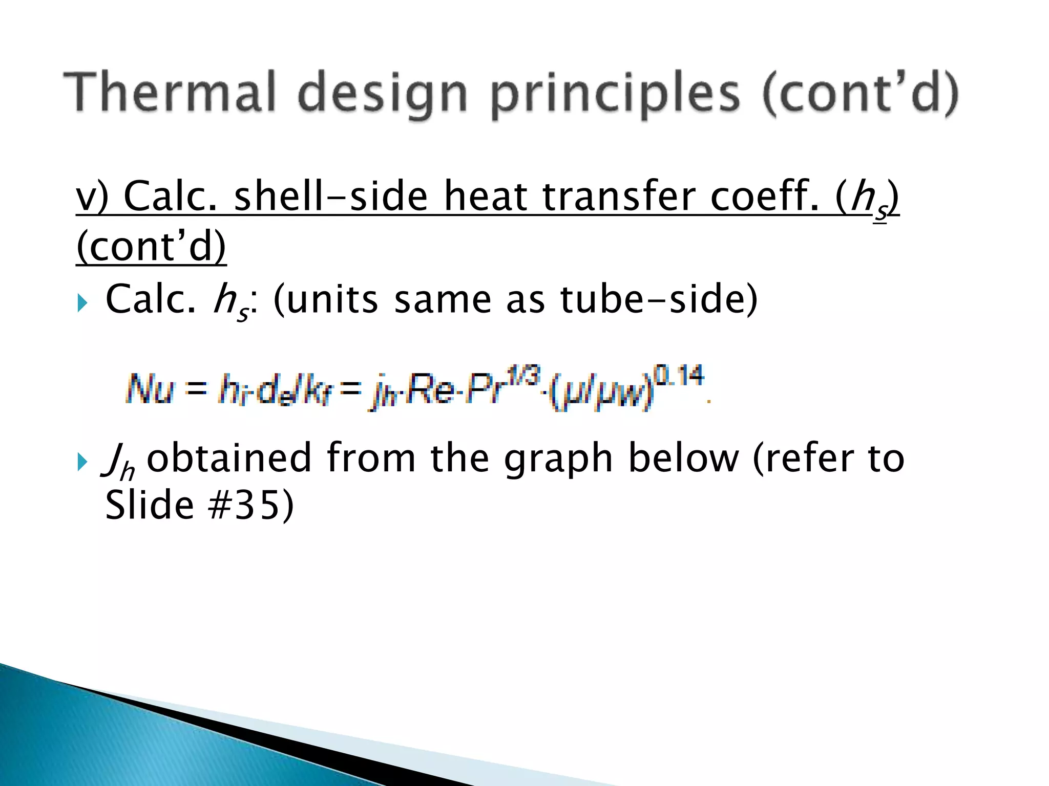
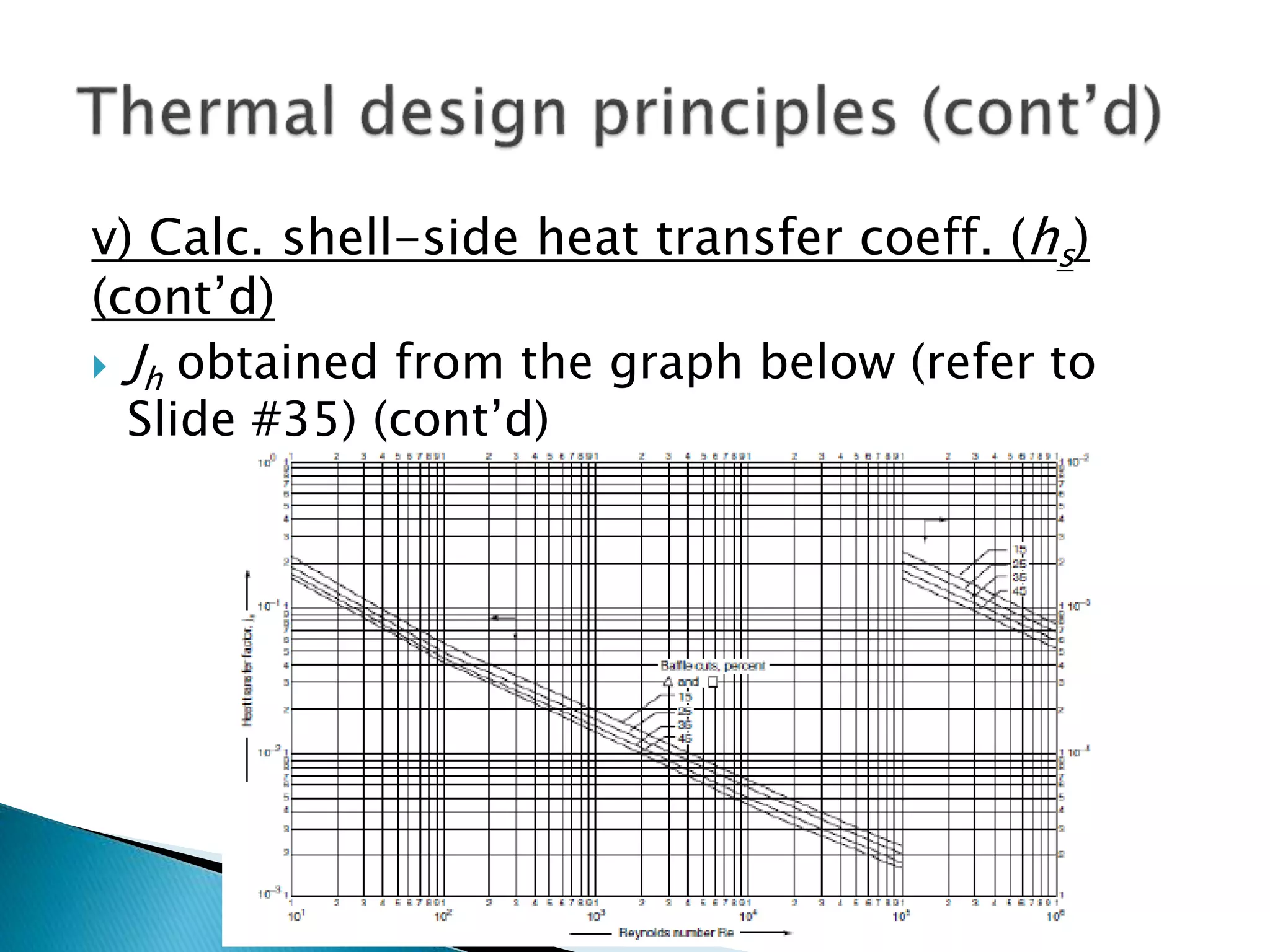
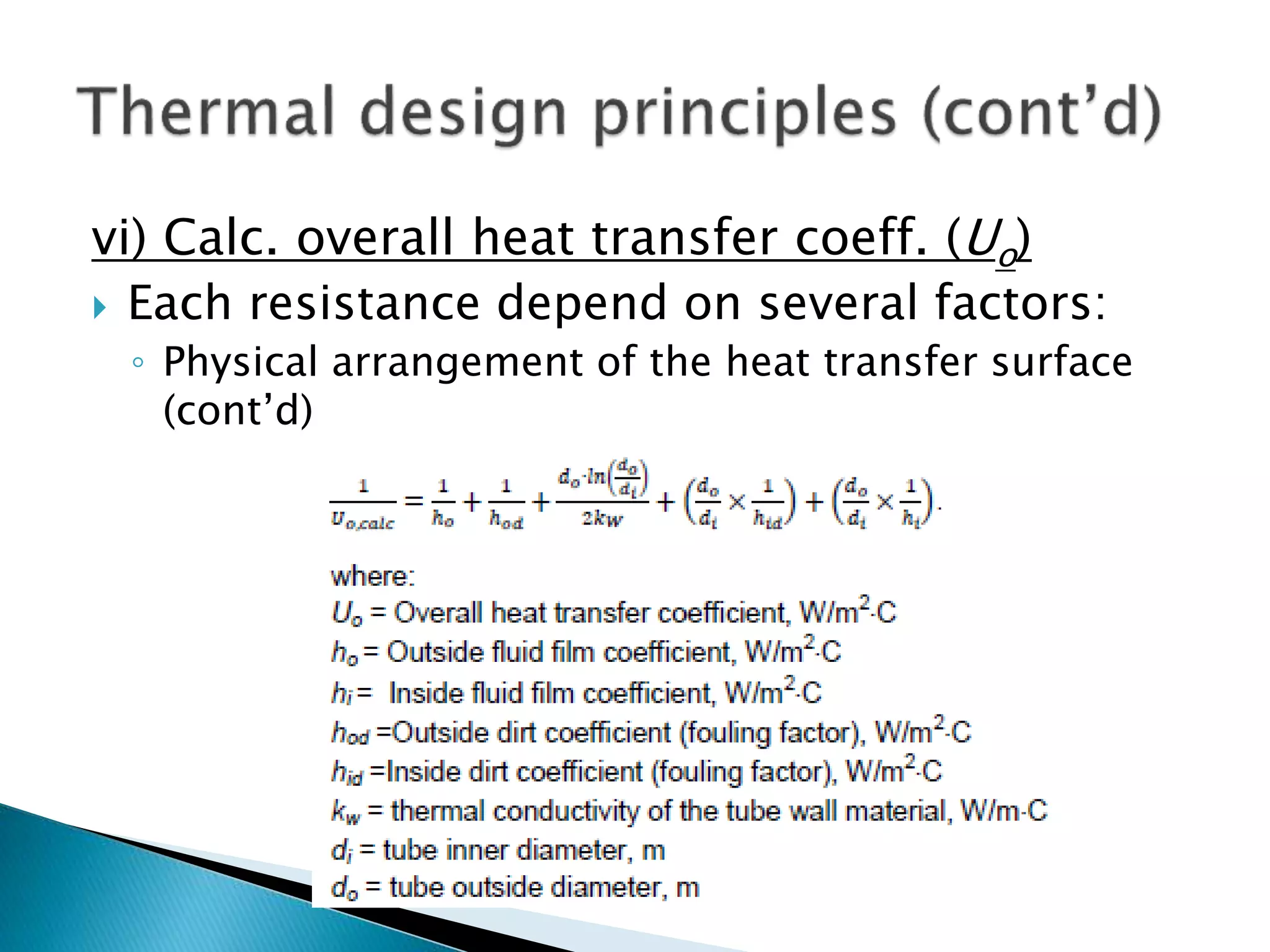
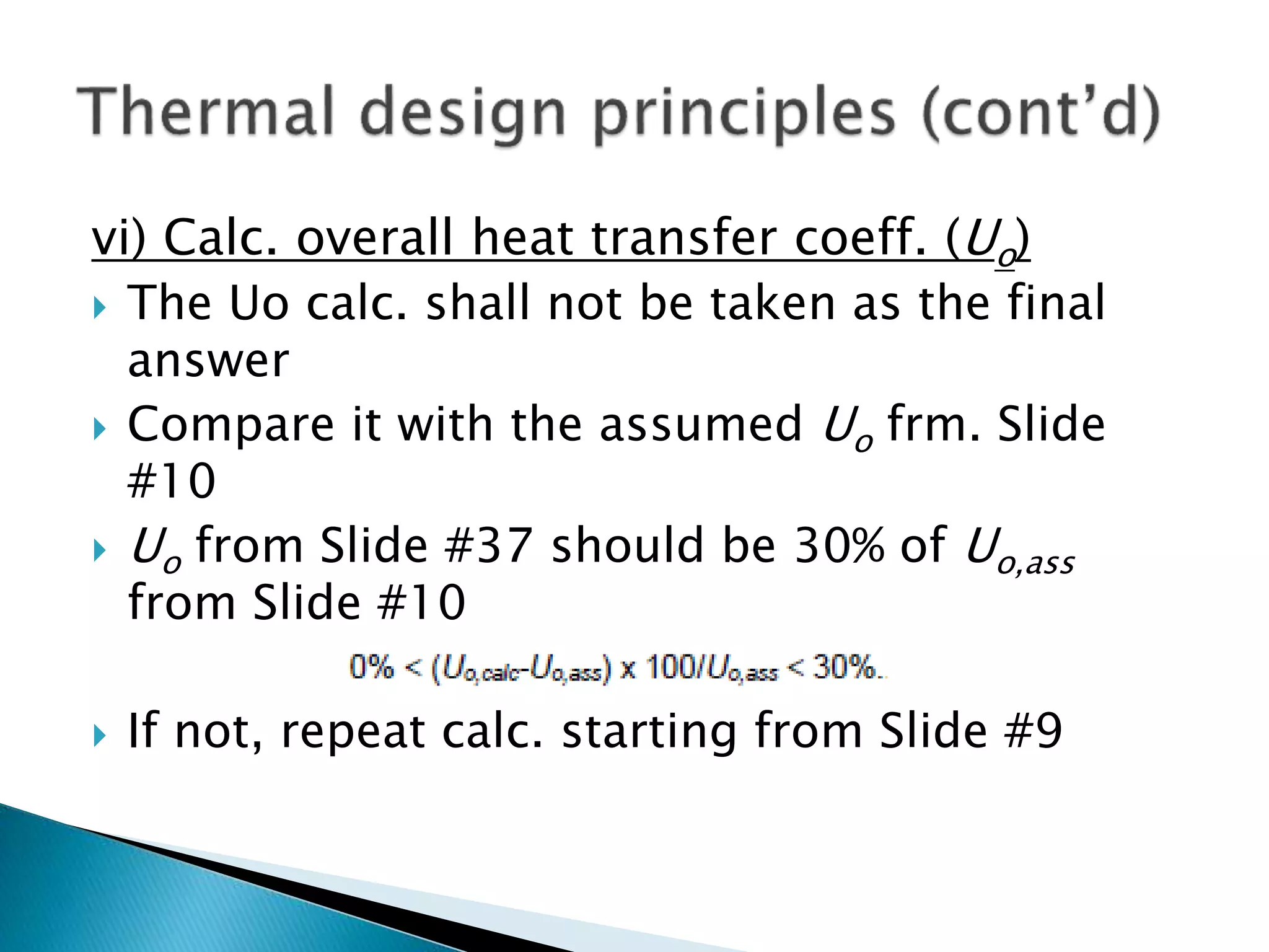
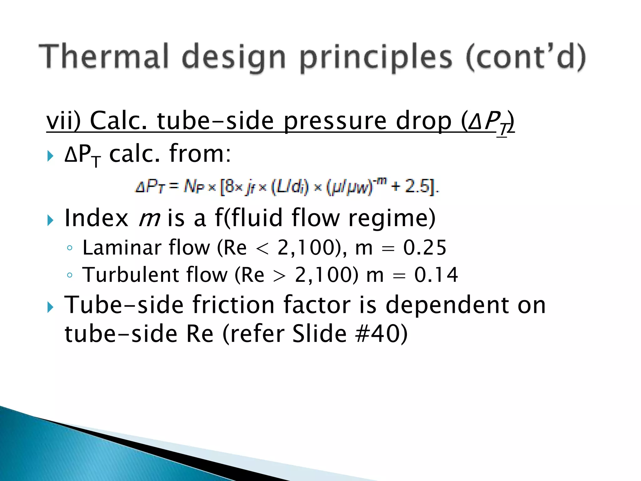
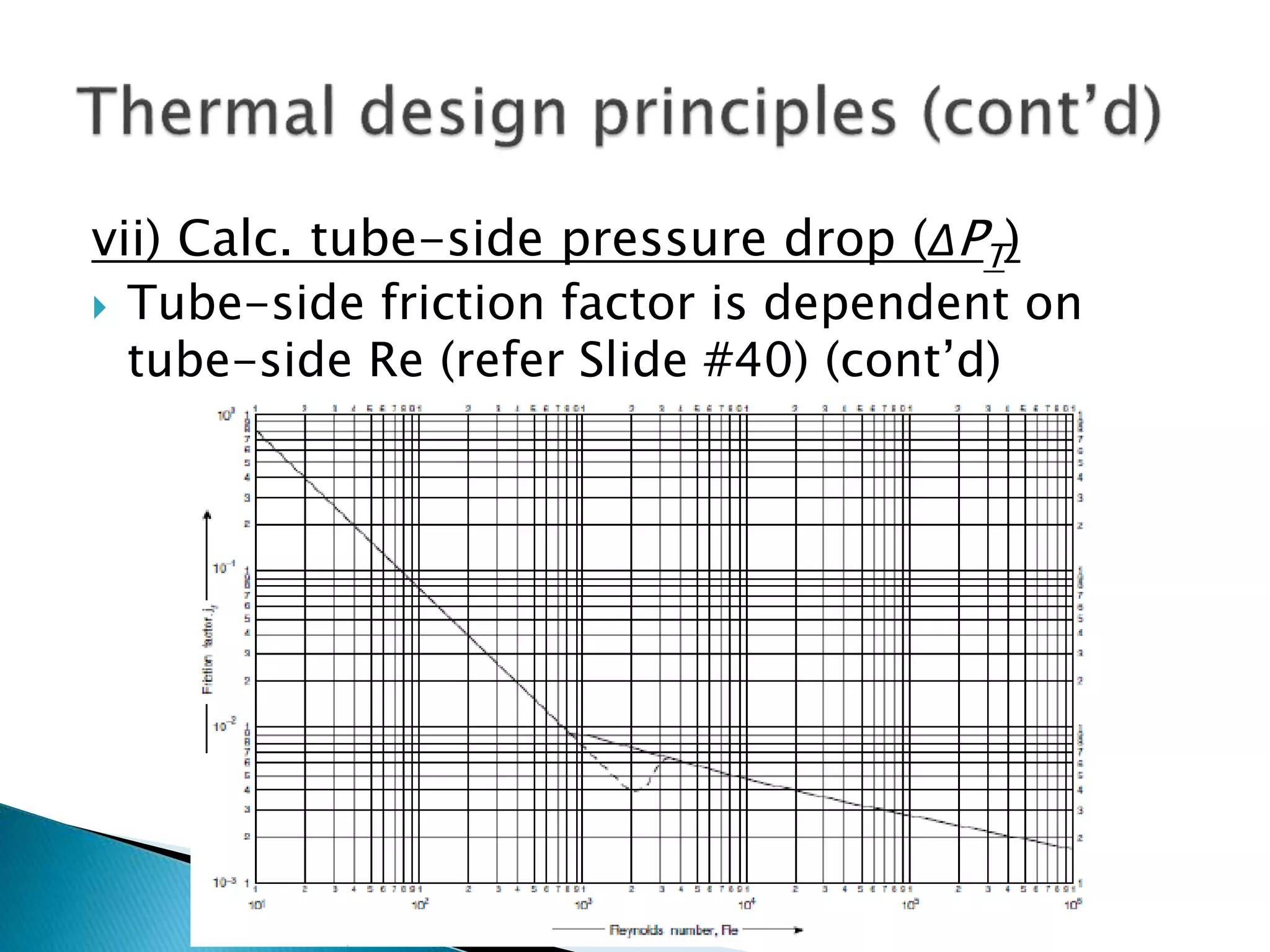
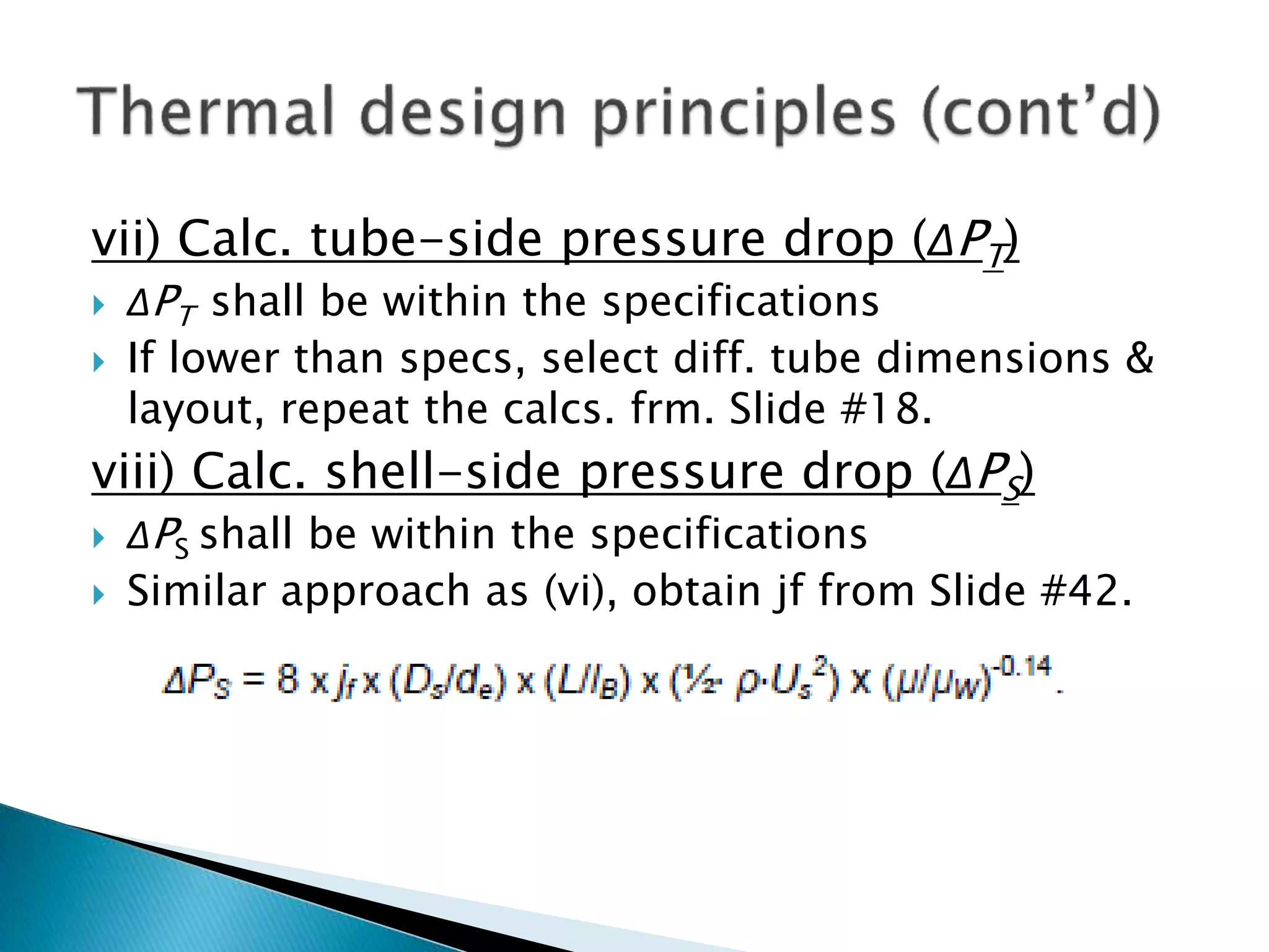
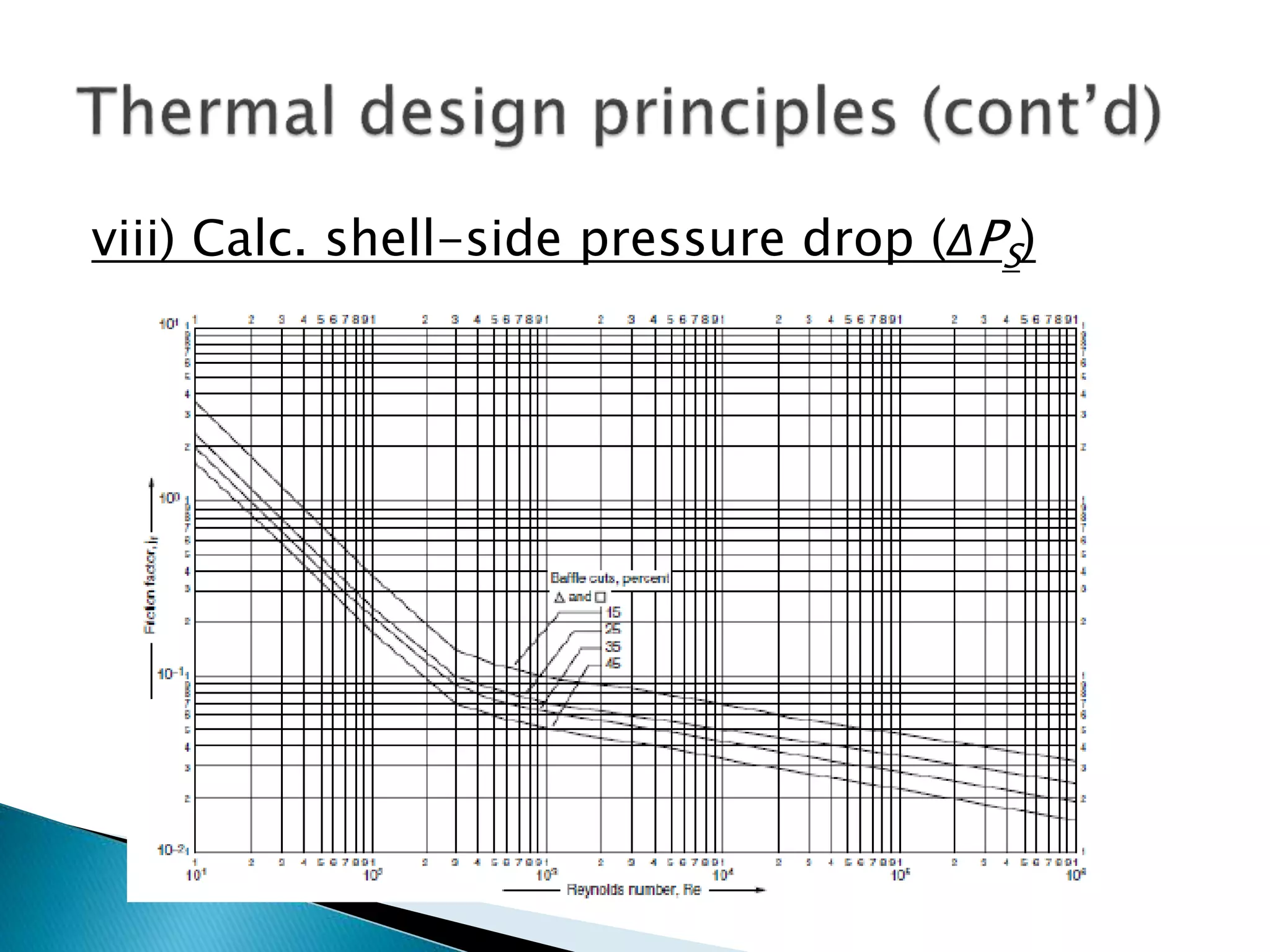


The document discusses the design and operational principles of shell and tube heat exchangers, including fluid flow arrangements (counter-current vs. co-current) and thermal design calculations. Key topics covered include determining overall duty, heat transfer coefficients, tube design specifications, and pressure drop calculations for both tube-side and shell-side fluids. The document emphasizes the importance of various design factors such as fluid type, viscosity, and layout for optimizing heat transfer efficiency.