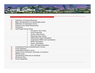
Course Outline
Definition of Energy Machines
Basic Components of a Centrifugal pump
Definition of Important Terms
Pressure and Head Relationship.
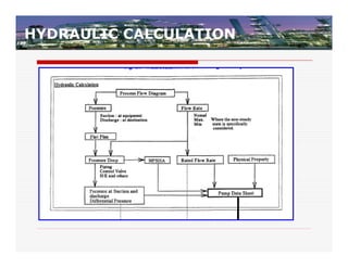
Hydraulics
Centrifugal Pump Sizing
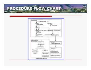
Procedure Flow Chart
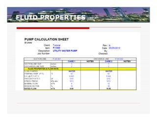
Fluid Properties
Suction Pipe Sizing
Discharge Pipe Sizing
Differential Head Calculation
Understand NPSH and Cavitations
NPSH Calculation
Power Calculation
Shut off Head Estimation
Understand Pump Characteristics Curves
Pump Selection
Understand System Curve
Pump Curve Correction (Viscosity Correction)
Affinity Laws
Temperature Rise due to pumping
Minimum Flow
Pump Datasheet
3.
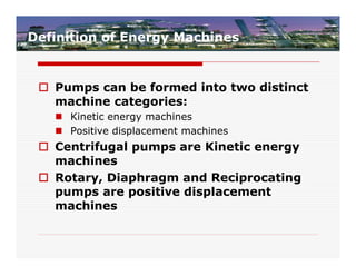
Definition of EnergyMachines
Pumps can be formed into two distinct
machine categories:
Kinetic energy machines
Positive displacement machines
Centrifugal pumps are Kinetic energy
machines
Rotary, Diaphragm and Reciprocating
pumps are positive displacement
machines
4.
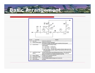
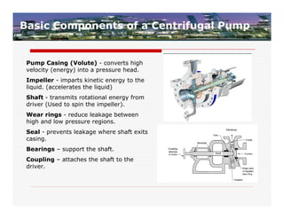
Basic Components ofa Centrifugal Pump
Pump Casing (Volute) - converts high
velocity (energy) into a pressure head.
Impeller - imparts kinetic energy to the
liquid. (accelerates the liquid)
Shaft - transmits rotational energy from
driver (Used to spin the impeller).
Wear rings - reduce leakage between
high and low pressure regions.
Seal - prevents leakage where shaft exits
casing.
Bearings – support the shaft.
Coupling – attaches the shaft to the
driver.
5.
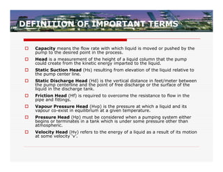
DEFINITION OF IMPORTANTTERMS
Capacity means the flow rate with which liquid is moved or pushed by the
pump to the desired point in the process.
Head is a measurement of the height of a liquid column that the pump
could create from the kinetic energy imparted to the liquid.
Static Suction Head (Hs) resulting from elevation of the liquid relative to
the pump center line.
Static Discharge Head (Hd) is the vertical distance in feet/meter between
the pump centerline and the point of free discharge or the surface of the
liquid in the discharge tank.
Friction Head (Hf) is required to overcome the resistance to flow in the
pipe and fittings.
Vapour Pressure Head (Hvp) is the pressure at which a liquid and its
vapour co-exist in equilibrium at a given temperature.
Pressure Head (Hp) must be considered when a pumping system either
begins or terminates in a tank which is under some pressure other than
atmospheric.
Velocity Head (Hv) refers to the energy of a liquid as a result of its motion
at some velocity ‘v’.
6.
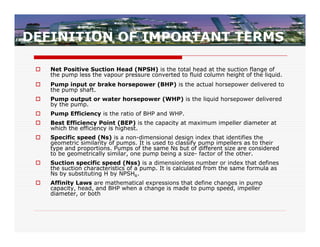
DEFINITION OF IMPORTANTTERMS
Net Positive Suction Head (NPSH) is the total head at the suction flange of
the pump less the vapour pressure converted to fluid column height of the liquid.
Pump input or brake horsepower (BHP) is the actual horsepower delivered to
the pump shaft.
Pump output or water horsepower (WHP) is the liquid horsepower delivered
by the pump.
Pump Efficiency is the ratio of BHP and WHP.
Best Efficiency Point (BEP) is the capacity at maximum impeller diameter at
which the efficiency is highest.
Specific speed (Ns) is a non-dimensional design index that identifies the
geometric similarity of pumps. It is used to classify pump impellers as to their
type and proportions. Pumps of the same Ns but of different size are considered
to be geometrically similar, one pump being a size- factor of the other.
Suction specific speed (Nss) is a dimensionless number or index that defines
the suction characteristics of a pump. It is calculated from the same formula as
Ns by substituting H by NPSHR.
Affinity Laws are mathematical expressions that define changes in pump
capacity, head, and BHP when a change is made to pump speed, impeller
diameter, or both
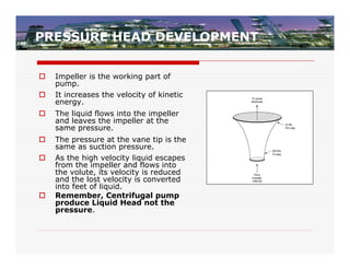
PRESSURE HEAD DEVELOPMENT
Impeller is the working part of
pump.
It increases the velocity of kinetic
energy.
The liquid flows into the impeller
and leaves the impeller at the
same pressure.
The pressure at the vane tip is the
same as suction pressure.
As the high velocity liquid escapes
from the impeller and flows into
the volute, its velocity is reduced
and the lost velocity is converted
into feet of liquid.
Remember, Centrifugal pump
produce Liquid Head not the
pressure.
10.
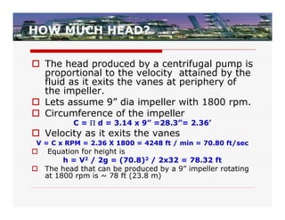
HOW MUCH HEAD?
The head produced by a centrifugal pump is
proportional to the velocity attained by the
fluid as it exits the vanes at periphery of
the impeller.
Lets assume 9” dia impeller with 1800 rpm.
Circumference of the impeller
C = d = 3.14 x 9” =28.3”= 2.36’
Velocity as it exits the vanes
V = C x RPM = 2.36 X 1800 = 4248 ft / min = 70.80 ft/sec
Equation for height is
h = V2 / 2g = (70.8)2 / 2x32 = 78.32 ft
The head that can be produced by a 9” impeller rotating
at 1800 rpm is ~ 78 ft (23.8 m)
11.
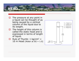
HEAD
The pressureat any point in
a liquid can be thought of as
being caused by a vertical
column of the liquid due to
its weight.
The height of this column is
called the static head and is
expressed in terms of length
of liquid.
Rule of Thumb: 1 kg/cm2 =
10 m Head (Water at SG = 1.0)
12.
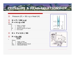
PRESSURE & HEADRELATIONSHIP
Pressure (P) = SG x g x Head (H)
H = P / (SG x g)
P = H x g x SG
Where
H = head, in meter
P = pressure, kPa
SG = specific gravity of liquid
g = 9.8 m/sec2
H = P x 2.31 / SG
P = H x SG
2.31
Where
H = head, in feet
P = pressure, in PSI
SG = specific gravity of liquid
2.31 = conversion factor
13.
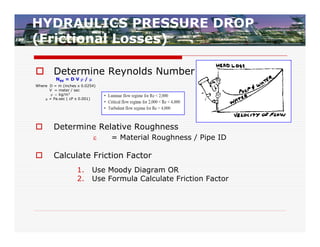
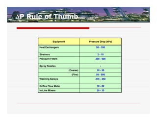
HYDRAULICS PRESSURE DROP
(FrictionalLosses)
Determine Reynolds Number
NRE = D V /
Where D = m (inches x 0.0254)
V = meter / sec
kg/m3
= Pa.sec ( cP x 0.001)
Determine Relative Roughness
= Material Roughness / Pipe ID
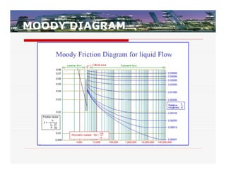
Calculate Friction Factor
1. Use Moody Diagram OR
2. Use Formula Calculate Friction Factor
FRICTION FACTOR FORMULA
f = 0.0055 x [ 1+(36/D +106/NRE)1/3] X 1.10
Where Dia. Of pipe in “inches”.
OR
16.
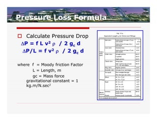
Pressure Loss Formula
Calculate Pressure Drop
P = f L v2 / 2 gc d
P/L = f v2 / 2 gc d
where f = Moody friction Factor
L = Length, m
gc = Mass force
gravitational constant = 1
kg.m/N.sec2
SUCTION PIPING DESIGN
CRITERIA
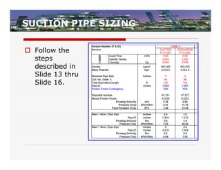
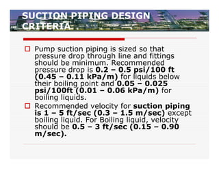
Pump suction piping is sized so that
pressure drop through line and fittings
should be minimum. Recommended
pressure drop is 0.2 – 0.5 psi/100 ft
(0.45 – 0.11 kPa/m) for liquids below
their boiling point and 0.05 – 0.025
psi/100ft (0.01 – 0.06 kPa/m) for
boiling liquids.
Recommended velocity for suction piping
is 1 – 5 ft/sec (0.3 – 1.5 m/sec) except
boiling liquid. For Boiling liquid, velocity
should be 0.5 – 3 ft/sec (0.15 – 0.90
m/sec).
24.
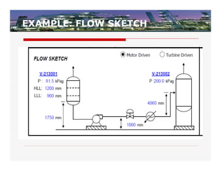
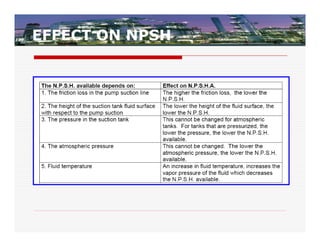
SUCTION PRESSURE
Vessel Pressure = 81.5 kPag
Liquid Level (From pump center line to
LLLL) = 1750-1000+900 = 1650 mm
Converting into pressure = 0.993 x 9.8 x
1.65 = 16.06 kPa [ Ref. Slide 16]
Suction Line Loss = 3.44 kPa [Ref. Slide 12-
15 and Slide 22]
Line Size =
Suction Pressure at Pump Flange = 81.5
+16.06 – 3.44 = 94.12 kPag
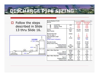
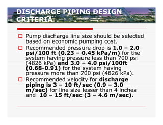
DISCHARGE PIPING DESIGN
CRITERIA
Pump discharge line size should be selected
based on economic pumping cost.
Recommended pressure drop is 1.0 – 2.0
psi/100 ft (0.23 – 0.45 kPa/m) for the
system having pressure less than 700 psi
(4826 kPa) and 3.0 – 4.0 psi/100ft
(0.68-0.91) for the system having
pressure more than 700 psi (4826 kPa).
Recommended velocity for discharge
piping is 3 – 10 ft/sec (0.9 – 3.0
m/sec) for line size lesser than 4 inches
and 10 – 15 ft/sec (3 – 4.6 m/sec).
27.
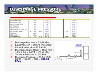
DISCHARGE PRESSURE
Discharge line loss = 23.04 kPa
Equipment P = 50 kPa (Assumed)
Control valve P = 68.95 kPa
Discharge Static Head = 4060 mm =
4.06 x 9.8 x 0.993 = 39.55 kPa
Terminal Pressure = 200 kPa
Discharge Pressure = 23.04 +50+
68.95 + 39.55 + 200 = 381.54
kPag
28.
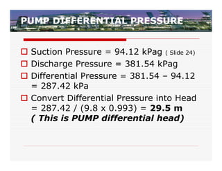
PUMP DIFFERENTIAL PRESSURE
Suction Pressure = 94.12 kPag ( Slide 24)
Discharge Pressure = 381.54 kPag
Differential Pressure = 381.54 – 94.12
= 287.42 kPa
Convert Differential Pressure into Head
= 287.42 / (9.8 x 0.993) = 29.5 m
( This is PUMP differential head)
29.
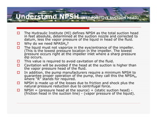
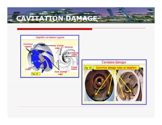
Understand NPSH (NET POSITIVE SUCTION HEAD)
The Hydraulic Institute (HI) defines NPSH as the total suction head
in feet absolute, determined at the suction nozzle and corrected to
datum, less the vapor pressure of the liquid in head of the fluid.
Why do we need NPASHA?
The liquid must not vaporize in the eye/entrance of the impeller.
(This is the lowest pressure location in the impeller. The lowest
pressure occurs right at the impeller inlet where a sharp pressure
dip occurs.
This value is required to avoid cavitation of the fluid.
Cavitation will be avoided if the head at the suction is higher than
the vapor pressure head of the fluid.
In addition, the pump manufacturers require a minimum NPSH to
guarantee proper operation of the pump, they call this the NPSHR,
where “R” stands for required.
NPSH is made up of the losses due to friction and shock plus the
natural pressure reduction due to centrifugal force.
NPSH = (pressure head at the source) + (static suction head) -
(friction head in the suction line) - (vapor pressure of the liquid).
PRESSURE POINTS WITHINTHE
PUMP
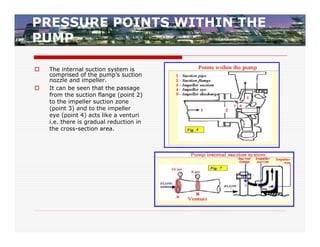
The internal suction system is
comprised of the pump’s suction
nozzle and impeller.
It can be seen that the passage
from the suction flange (point 2)
to the impeller suction zone
(point 3) and to the impeller
eye (point 4) acts like a venturi
i.e. there is gradual reduction in
the cross-section area.
32.
PRESSURE PROFILE INSIDEA PUMP
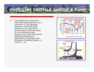
The impeller eye is the point
where the static pressure is at a
minimum, P4. During pump
operation, if the local static
pressure of the liquid at the
lowest pressure becomes equal
to or less than the vapor
pressure (Pv) of the liquid at the
operating temperature,
vaporization of the liquid (the
formation of bubbles) begins i.e.
when P4 < Pv.
33.
UNDERSTAND NPSH…
Itis impossible to design a centrifugal
pump that exhibits absolutely no pressure
drop between the suction inlet and its
minimum pressure point, which normally
occurs at the entrance to the impeller
vanes.
If the pressure is not sufficient, some of the
water will change state (liquid to vapor)
and cavitations occur.
It thus reflects the amount of head
loss that the pump can sustain
internally before the vapor pressure is
reached.
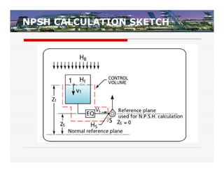
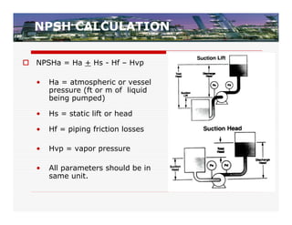
NPSH CALCULATION
NPSHa= Ha + Hs - Hf – Hvp
• Ha = atmospheric or vessel
pressure (ft or m of liquid
being pumped)
• Hs = static lift or head
• Hf = piping friction losses
• Hvp = vapor pressure
• All parameters should be in
same unit.
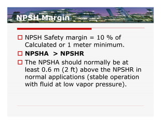
38.
NPSH Margin
NPSHSafety margin = 10 % of
Calculated or 1 meter minimum.
NPSHA > NPSHR
The NPSHA should normally be at
least 0.6 m (2 ft) above the NPSHR in
normal applications (stable operation
with fluid at low vapor pressure).
39.
NPSH CALCULATION
1.Vessel Pressure = 81.5 kPag
2. Liquid Level (From pump center line to LLLL) = 1750-1000+900
= 1650 mm Converting into pressure = 0.993 x 9.8 x 1.65 =
16.06 kPa [ Ref. Slide 16]
3. Suction Line Loss = 3.44 kPa [Ref. Slide 12-15]
4. Suction Pressure at Pump Flange = 81.5 +16.06 – 3.44 =
94.12 kPag
5. Vapor Pressure = 8.65 kPa
6. NPSHa = Suction pressure – Vapor Pressure = (94.12 + 93.5) –
8.65 = 178.97 kPa
7. Convert Pressure into head = 178.97 /(9.8 x 0.993) =18.38 m
40.
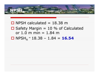
NPSHA
NPSH calculated= 18.38 m
Safety Margin = 10 % of Calculated
or 1.0 m min = 1.84 m
NPSHA = 18.38 – 1.84 = 16.54
41.
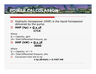
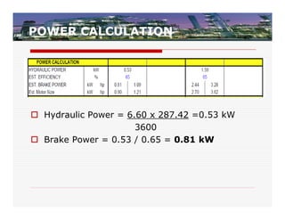
POWER CALCULATION
Hydraulichorsepower (HHP) is the liquid horsepower
delivered by the pump.
HHP (hp) = Q x P
1714
Where
Q = Capacity, gpm
P= Total Differential Pressure, psi
HHP (kW) = Q x P
3600
Where
Q = Capacity, m3 / h
P= Total Differential Pressure, kPa
Conversion from kW to hp
1 hp (British) = 0.7457 kW
42.
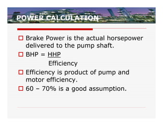
POWER CALCULATION
BrakePower is the actual horsepower
delivered to the pump shaft.
BHP = HHP
Efficiency
Efficiency is product of pump and
motor efficiency.
60 – 70% is a good assumption.
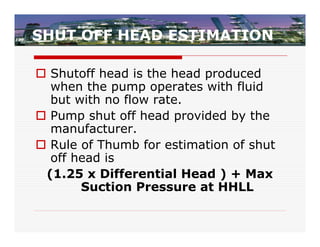
SHUT OFF HEADESTIMATION
Shutoff head is the head produced
when the pump operates with fluid
but with no flow rate.
Pump shut off head provided by the
manufacturer.
Rule of Thumb for estimation of shut
off head is
(1.25 x Differential Head ) + Max
Suction Pressure at HHLL
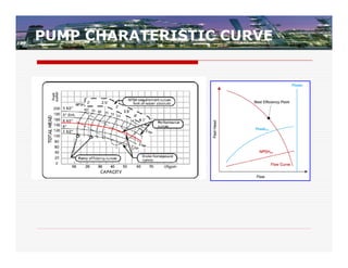
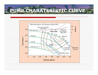
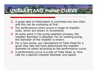
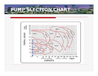
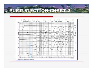
UNSERSTAND PUMP CURVE
A great deal of information is crammed into one chart
and this can be confusing at first.
The performance chart covers a range of impeller
sizes, which are shown in increments.
At some point in the pump selection process, the
impeller diameter is selected. For an existing pump,
the diameter of the impeller is known.
For a new pump, our calculations of Total Head for a
given flow rate will have determined the impeller
diameter to select according to the performance curve.
A performance curve is a plot of Total Head vs. flow
rate for a specific impeller diameter and speed.
51.
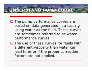
UNSERSTAND PUMP CURVE
The pump performance curves are
based on data generated in a test rig
using water as the fluid. These curves
are sometimes referred to as water
performance curves.
The use of these curves for fluids with
a different viscosity than water can
lead to error if the proper correction
factors are not applied.
52.
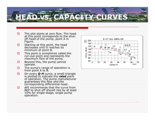
HEAD vs. CAPACITYCURVES
The plot starts at zero flow. The head
at this point corresponds to the shut-
off head of the pump, point A in
Figure.
Starting at this point, the head
decreases until it reaches its
minimum at point B.
This point is sometimes called the
run-out point and represents the
maximum flow of the pump.
Beyond this, the pump cannot
operate.
The pump's range of operation is
from point A to B.
On every Q–H curve, a small triangle
is plotted to indicate the rated point
of operation. The pump manufacturer
guarantees this flow and the
corresponding differential head.
API recommends that the curve from
BEP to shut-off should rise by at least
10% for single-stage, single pump
operation.
53.
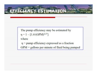
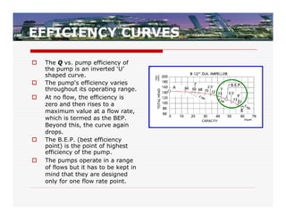
EFFICIENCY CURVES
The Q vs. pump efficiency of
the pump is an inverted ‘U’
shaped curve.
The pump's efficiency varies
throughout its operating range.
At no flow, the efficiency is
zero and then rises to a
maximum value at a flow rate,
which is termed as the BEP.
Beyond this, the curve again
drops.
The B.E.P. (best efficiency
point) is the point of highest
efficiency of the pump.
The pumps operate in a range
of flows but it has to be kept in
mind that they are designed
only for one flow rate point.
54.
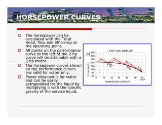
HORSEPOWER CURVES
The horsepower can be
calculated with the Total
Head, flow and efficiency at
the operating point.
All points on the performance
curve to the left of the 2 hp
curve will be attainable with a
2 hp motor.
The horsepower curves shown
on the performance curves
are valid for water only.
Power obtained is for water
and can be easily
extrapolated for the liquid by
multiplying it with the specific
gravity of the service liquid.
55.
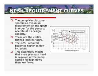
NPSH REQUIREMENT CURVES
The pump Manufacturer
specifies a minimum
requirement on the NPSH
in order for the pump to
operate at its design
capacity.
These are the vertical
dashed lines in Figure.
The NPSH required
becomes higher as flow
increases.
This essentially means
that more pressure head
is required at the pump
suction for high flows
than low flows.
56.
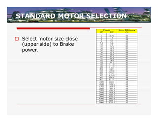
Pump Selection
Inselecting a pump, one of the concerns is
to optimize pumping efficiency. It is good
practice to examine several performance
charts at different speeds to see if one
model satisfies the requirements more
efficiently than another.
Whenever possible the lowest pump speed
should be selected, as this will save wear
and tear on the rotating parts.
57.
Pump Selection Rules-of-Thumb
Select the pump based on rated conditions.
The BEP should be between the rated point
and the normal operating point.
The head/capacity characteristic-curve
should continuously rise as flow is reduced
to shutoff (or zero flow).
The pump should be capable of a head
increase at rated conditions by installing a
larger impeller.
The pump should not be operated below
the manufacturer’s minimum continuous
flow rate.
58.
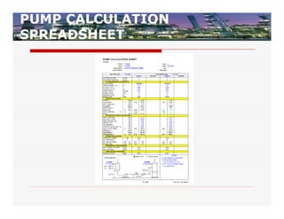
PUMP SPECIFICATIONS
Flow Rate : 6 m3/h = 26.42 gpm
Differential Head : 29.5 m = 96.8 ft
NPSHa = 16.54 m = 54.26 ft
Brake Power = 0.81 kW = 1.10 hp
Rated Motor = 1.12 kW = 1.5 hp
Shut-off Head = 458.3 kPa
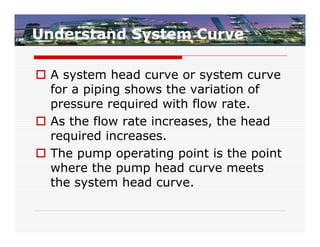
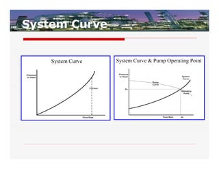
Understand System Curve
A system head curve or system curve
for a piping shows the variation of
pressure required with flow rate.
As the flow rate increases, the head
required increases.
The pump operating point is the point
where the pump head curve meets
the system head curve.
Pump Curve Corrections
The pump curves are generated while
testing the pump using cold water as
the liquid. The curve is fixed for a
particular speed, impeller diameter,
and water.
When any of these change, the pump
flow and head generated will differ.
the curves can be corrected to obtain
a performance map without retesting
pump with modified conditions.
65.
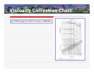
Viscosity Correction
viscosityas a property of any fluid that is measure of
its resistance to flow.
As the liquid flows through the pump, hydrodynamic
losses are increased due to higher viscosity, as a
result it is observed that when a viscous fluid is
handled by a centrifugal pump:
The brake horsepower requirement increases.
There is a reduction in the head generated by the
pump.
Capacity reduction occurs with moderate and high
viscosities.
There is a decrease in the pump efficiency.
66.
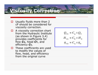
Viscosity Correction
Usuallyfluids more than 2
cP should be considered for
viscosity correction.
A viscosity correction chart
from the Hydraulic Institute
(as shown in Figure 3.4)
provides coefficients for
flow Cq, head Ch, and
efficiency Cη.
These coefficients are used
to modify the values of
flow, head, and efficiency
from the original curve
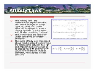
Affinity Laws
The ‘Affinity laws’ are
mathematical expressions that
best define changes in pump
capacity, head, and power
absorbed by the pump when a
change is made to pump speed,
with all else remaining constant.
The Affinity laws are valid only
under conditions of constant
efficiency.
The pump affinity laws mentioned
above maybe utilized to determine
the relationship between flow ‘Q’
and impeller diameter as well as
to predict Head ‘H’ and Power ‘P’
values with change in impeller
diameter, whilst speed is kept
constant.
70.
Temperature Rise Dueto Pumping
Basic Equation
H 1
Tr
Cp 778 e 1 [British System]
H 1
Tr
Cp 427 e 1 [Metric System]
where
Cp - specific heat of the liquid (BTU/lb/°F or kCal/kg °C)
Rule of Thumb: Generally 1.00 for water and 0.5 for hydrocarbons
H = differential head (feet or meter)
e = pump efficiency in decimal (i.e. 78 % = 0.78)
Tr = Temperature Rise, °F or °C
71.
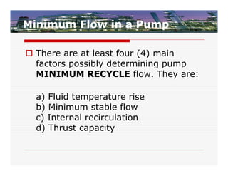
Minimum Flow ina Pump
There are at least four (4) main
factors possibly determining pump
MINIMUM RECYCLE flow. They are:
a) Fluid temperature rise
b) Minimum stable flow
c) Internal recirculation
d) Thrust capacity
72.
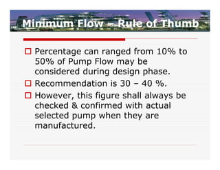
Minimum Flow –Rule of Thumb
Percentage can ranged from 10% to
50% of Pump Flow may be
considered during design phase.
Recommendation is 30 – 40 %.
However, this figure shall always be
checked & confirmed with actual
selected pump when they are
manufactured.
73.
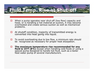
Fluid Temp. Riseat Shut-off
When a pump operates near shut-off (low flow) capacity and
head, or is handling a hot material at suction, it may become
overheated and create serious suction as well as mechanical
problems.
At shutoff condition, majority of transmitted energy is
converted into heat going into liquid.
To avoid overheating due to low flow, a minimum rate should
be recognized as necessary for proper heat dissipation.
The maximum temperature rise recommended for any
fluid is 15°F (8°C) except when handling cold fluids or using a
special pump designed to handle hot fluid, such as a boiler
feed water pump of several manufacturers.
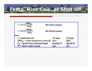
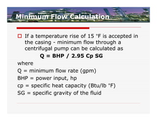
Minimum Flow Calculation
If a temperature rise of 15 °F is accepted in
the casing - minimum flow through a
centrifugal pump can be calculated as
Q = BHP / 2.95 Cp SG
where
Q = minimum flow rate (gpm)
BHP = power input, hp
cp = specific heat capacity (Btu/lb °F)
SG = specific gravity of the fluid


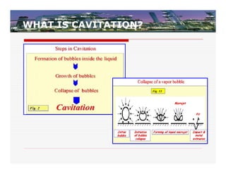
![FRICTION FACTOR FORMULA
f = 0.0055 x [ 1+(36/D +106/NRE)1/3] X 1.10
Where Dia. Of pipe in “inches”.
OR](https://image.slidesharecdn.com/centrifugalpumpsizingselectionanddlesignpractices-12758726575297-phpapp01-120708074558-phpapp02/85/Centrifugalpumpsizingselectionandd-lesignpractices-12758726575297-phpapp01-15-320.jpg)
![SUCTION PRESSURE
Vessel Pressure = 81.5 kPag
Liquid Level (From pump center line to
LLLL) = 1750-1000+900 = 1650 mm
Converting into pressure = 0.993 x 9.8 x
1.65 = 16.06 kPa [ Ref. Slide 16]
Suction Line Loss = 3.44 kPa [Ref. Slide 12-
15 and Slide 22]
Line Size =
Suction Pressure at Pump Flange = 81.5
+16.06 – 3.44 = 94.12 kPag](https://image.slidesharecdn.com/centrifugalpumpsizingselectionanddlesignpractices-12758726575297-phpapp01-120708074558-phpapp02/85/Centrifugalpumpsizingselectionandd-lesignpractices-12758726575297-phpapp01-24-320.jpg)
![NPSH CALCULATION
1. Vessel Pressure = 81.5 kPag
2. Liquid Level (From pump center line to LLLL) = 1750-1000+900
= 1650 mm Converting into pressure = 0.993 x 9.8 x 1.65 =
16.06 kPa [ Ref. Slide 16]
3. Suction Line Loss = 3.44 kPa [Ref. Slide 12-15]
4. Suction Pressure at Pump Flange = 81.5 +16.06 – 3.44 =
94.12 kPag
5. Vapor Pressure = 8.65 kPa
6. NPSHa = Suction pressure – Vapor Pressure = (94.12 + 93.5) –
8.65 = 178.97 kPa
7. Convert Pressure into head = 178.97 /(9.8 x 0.993) =18.38 m](https://image.slidesharecdn.com/centrifugalpumpsizingselectionanddlesignpractices-12758726575297-phpapp01-120708074558-phpapp02/85/Centrifugalpumpsizingselectionandd-lesignpractices-12758726575297-phpapp01-39-320.jpg)
![Temperature Rise Due to Pumping
Basic Equation
H 1
Tr
Cp 778 e 1 [British System]
H 1
Tr
Cp 427 e 1 [Metric System]
where
Cp - specific heat of the liquid (BTU/lb/°F or kCal/kg °C)
Rule of Thumb: Generally 1.00 for water and 0.5 for hydrocarbons
H = differential head (feet or meter)
e = pump efficiency in decimal (i.e. 78 % = 0.78)
Tr = Temperature Rise, °F or °C](https://image.slidesharecdn.com/centrifugalpumpsizingselectionanddlesignpractices-12758726575297-phpapp01-120708074558-phpapp02/85/Centrifugalpumpsizingselectionandd-lesignpractices-12758726575297-phpapp01-70-320.jpg)