SlideShare a Scribd company logo
1 of 113
Pumps /Centrifugal Pumps/Positive
displacemnt pumps
Flow through the vanes of a Centrifugal Pumps
What are we going to discuss in Pumps, please note down so that
nothing important is skipped.
 See the Pumps used in a thermal power station
 Purposes and classification of Pumps
 Working Principle of Centrifugal, Rotary and Reciprocating
pumps.
 Parts and function of each
 Heads acting on a centrifugal pump
 NPSHr, NPSHa and Cavitation
 Pumps characteristics
 Series and parallel Operation
THE PUMPS TOPIC CAN BE BROADLY CLASSIFIED INTOTWO
CATEGORIES
Pumps General
 PUMPS USED IN ATHERMAL POWER STATION
In pumps general we shall study application or usages of
pumps, classification, working principle of each type of
pump, details of the components, construction, different
types of impellers, different types of casings, end suction,
double suction, Horizontal & vertical pumps, Surface and
submerged pumps, single stage and multistage pumps,
Monoblock and coupled pumps, shaft sealing
arrangement, Gland pacing & mechanical seal stuffing,
hydraulic balancing of impellers etc.
Head acting on a Centrifugal pump, Static suction lift,
Static suction head, static lift and static head, static
discharge head, Total head under different discharging
conditions, Net Positive suction head, vapor pressure,
frictional head loss, Velocity head, NPSHa, NPSHr and
cavitations.
Thermal Power Station Pumps includes:
Descriptions, Design features, components, materials,
location and working parameters of BFP, CEP, DRIP
PUMPS, COOLING WATER PUMPS, TURBINE MAIN LUB
OIL PUMP,, AC & DC Lub Oil Pumps, Ash water Pumps
Slurry Pump, Chemical handling Pumps, dosing Pumps
and many small lubricating Oil as positive displacement
pumps.
What Does Pumps do?
Pumps utilize the input energy of a electrical
motor or a diesel engine and convert it into
pressure energy of the liquid so that it can be
elevated from lower elevation to higher
elevation as in the case of high rise buildings or
from one point to another as in the case of
municipal water supply system.
A large number of pumps of the different types
are used in every power station and a good
knowledge of these hydraulic machines will
help them keep running most efficiently.
What are the Applications:
Pumps can be used on clear water, lubricating
oils, crude oils chemicals, pulps, slurries and
almost liquid of any kind and density. Only thing
required is it should be able to flow. They can also
be used for creating vacuum.
Essential data required in selection of centrifugal pump.
1. Number of units required.
2. Nature of the liquid to be Pumped. Is the liquid
a. Fresh or salt water, acid or alkali, oil gasoline, slurry or
paper stock
b. Cold or hot and if hot what is the temperature? What is
vapor pressure of the liquid at the pumping
temperature?
c. What is the specific gravity?
d. Is it viscous or Non viscous?
e. Clear and free from suspended matter, dirty or gritty?
f. What is the chemical nature of the liquid, Chemical
analysis and Ph value etc.
3. Capacity
What is the required capacity as well as minimum and
maximum amount of the liquid the pump will ever be
called upon to deliver
4. Suction Condition. Is there
a. A suction Pressure
b. Or a Suction Head
c. What are the length and diameter of the suction pipe
5. Discharge Conditions.
a. What s static head
b. What is the friction head
c. What is maximum discharge pressure against which
the pump must deliver the liquid.
6. Total Head.
Variation in item 4 & 5 will cause variation in the total
head.
7. Is the service continuous or intermittent?
8. Is the pump to be installed in horizontal or vertical
position?
Is the later in clear water or muddy liquid.
9. What type of power is available to drive the pump.
What is the characteristics of the driving unit.
10.What space, weight or transportation limitations are
involved.
10.Location of installation
a. Geographical location
b. Elevation above sea level
c. Indoor or outdoor installation
d. Range of ambient temperature
12.Are there special requirement or marked preference
with reference to design , construction , sealing and
performance of the pump?
Power input :The power required to drive any
class or type of the pump can be computed from
P = FHS/3960E in fps
Where P is the Power input, hp
F liquid flow rate in gpm
H =Total head on the pump in ft of the liquid
handled
S = Liquid specific gravity
E = pump efficiency
Head
PUMP CALCULATIONS:
Q xTotal Head (Hd- Hs) x d x g
Hydraulic Power = ------------------------------------------
ORWHP 1000
Where:
Q = Fluid Flow in meter in M 3 / Sec
Hd = Discharge Head
Hs = Suction Head in
d = Fluid density Kg/m3
g = Acceleration due to gravity m/sec2
Hydraulic Power
Pump Shaft Power Ps = --------------------------------
Pump Efficiency
Pump Shaft Power Ps
Electrical Motor Power = --------------------------
Motor Efficiency
Pumps Classification
PUMP
Dynamic Pumps Positive Displacement pumps
I I
----------------------------------- --------------------
I I I I I I
Centrifugal Turbine Propeller Jet Reciprocating Rotary
I I I
Radial flow Single suction ------------------------------- -------------
Radial flow Double suction I I I I
Mixed Flow Piston type Plunger type Diaphragm Ext. Gear
Special Purpose I I I Int. GearType
- ------------------------------- Sliding vane
I I Screw t type
Single acting Double Acting LobeType
Singlex Radial Plunger
Duplex
Triplex
Quardriplex
• Liquid is forced into impeller
• Vanes pass kinetic energy to
liquid: liquid rotates and leaves
impeller
• Volute casing converts kinetic
energy into pressure energy
INTHE FIGURE IS SHOWN A
RADIAL FLOW
CENTRIFUGAL PUMP
Working Principle of a
Centrifugal Pump:
Radial Flow
Impeller
One of the most commonly used type of Pump in the
thermal power station is a Centrifugal Pump.
 Whether the pump is a single stage or multistage
pump like BFP or CEP.
 Whether it is on the surface / horizontal with the shaft
axis horizontal orVertical Pumps like CWP, CEP Pumps.
Turbine lubricating oil pumps are also vertical pumps.
 End suction or double suction like BFP, Booster pump,
TGECWP, SGECWP or many other similar pumps.
 Most above pumps are Centrifugal pumps, which
means these pumps utilize centrifugal force by the
rotating impeller, increases kinetic energy of the liquid
and throw it into the volute casing. Here the Kinetic
energy is converted into static pressure.
 Another big feature of every centrifugal pumps pump
is that the pump can deliver any flow from zero to
100% , rotational speed being constant.This is
achieved by throttling the discharge valve.
 This means that the pump can be operated to deliver
any flow between zero to full flow against a specified
head.
 A centrifugal pump is started by closing the discharge
valve and when the pump develop full shut off head
or pressure the discharge valve is opened slowly and
kept at the desired flow.
 If the speed of the pump is changed the pump
characteristics will change.
 This can be understood by the figure on the next slide.
On the other hand a positive displacement pump is
entirely different from a Centrifugal pump.
It delivers a fixed volume during each revolution of the
rotor or the displacement of the piston in a
reciprocating pump and this is dependent upon the
speed of rotation.
They work by trapping action.
Higher the speed higher is the delivery rate lesser the
speed lesser the delivery rate.
Now after a positive displacement draws the fixed
quantity during suction period the same is delivered
during rest of the period of rotation positively.
There is no way that the fluid can re-circulate back like
centrifugal pumps.The pressure is build by the resistance
the fluid encounters during flow in the delivery pipe and
also by the work.
Major application is in hydraulic pumps, lubricating oil
pumps, fuel oil pumps.They are good for viscous liquid
like lubricants.The pressure in the delivery pipe is
adjusted by using a relief valve.
The excess fluid flows back to suction tank.
Some of the these pumps are External and internal gear
type pump, Screw pumps, Sliding vane pump and many
more other types.
• Liquid is forced into impeller
• Vanes pass kinetic energy to
liquid: liquid rotates and leaves
impeller
• Volute casing converts kinetic
energy into pressure energy
INTHE FIGURE IS SHOWN A
RADIAL FLOW
CENTRIFUGAL PUMP
Working Principle of a
Centrifugal Pump:
Radial Flow
Impeller
Components of a Centrifugal Pump
Flow through theVolute casing of a centrifugal Pump
CutView of a Single stage Centrifugal Pump
 Understanding Centrifugal Pumps Nomenclature:
 If the Pump is having single impeller and casing it is called single
stage pump
 If the pump is having more than one impeller andVolute casings
or cavities or passages it is called multistage pump.
 If the pump shaft is laid horizontal it is called horizontal pump.
 If the pump shaft is vertical it is called vertical pump.
 If the pump is laid on surface it is called surface pump.
 If the pumps is lowered into water or any other liquid it is called
submerged pump.
 If the pump is meant for handling lubricating oil it is called
lubricating oil pump.
 If the pump is meant for handling slurries it is called slurry
pump.
 If it is for Boiler feed water application it is called Boiler feed
water pump or similar.
 If the pump is low pressure pump it is called Low pressure
pump.
 If the pump is meant to deliver high pressure it is called high
pressure pump. Such pumps are usually multistage pump.
A single stage end suction Centrifugal Pump
Single or end suction Multistage Centrifugal Pump
Suction
Discharge Five Stage Impeller
A single stage double suction impeller
Double inlet Impeller
Suction
A more clear view of double suction impeller showing
double suction impeller, Casing, water chambers,
wearing ring, Shaft sealing etc.
Actually these pump are usually multistage, vertical and submerged , they are called
turbine pump due to earlier concept of turbine like arrangement, otherwise they are
radial flow multistage vertical pumps. They were meant for drawing water from wells
where the water level was sufficient deep. The casings are called BOWL. At the
surface you will see only motor and discharge pipe. The motor shaft is coupled to the
line shafts and line shafts are coupled to the pumps shafts. Some times the motor
shaft is hollow and the line shaft passes through the hollow motor shaft and is
coupled at the top with an arrangement of lift adjustment. The lift adjustment is
required to establish the necessary running clearance between the semi open
impeller and impeller seat and provide centering in case of closed impeller. The line
shafts bearings can be made of bronze or rubber. Rubber bearings called CUTLLESS
bearings.
Different figures of horizontal split case radial flow centrifugal pump. It is worth
noting that both suction and discharge pipes are horizontal and suction pipe is
usually one pipe size bigger than the discharge. So to identify the suction and
discharge is very easy. This is to keep the suction chambers flooded with water and
prevent cavitation. They are normally horizontal though in vertical orientation are
also available. They can be seen in every pump house . In TPS the booster pump
used in the suction of BFP is this type. We can see that the shaft passes through the
pump and is supported on both sides. It therefore uses two stuffing box and two
bearing brackets with double row self aligning ball bearings. Gland packings in the
stuffing box are cooled by the pumpage, which is a small tubing connection from the
top of volute casing and attached to the stuffing box. To establish the correct
direction of rotation, stand behind the motor facing the coupling, and see that it
rotates towards the discharge.
Mixed flow pumps are a mix of Pure radial flow & Pure axial flow pumps, hence
application is for large flows and medium pressure. They find application in
condenser cooling water circulation system, raw water system and similar
application. One thing is to be noted that what ever pressure rise will be there it
will be due to radial component. Radial means change in path of flow by 900
and axial flow means straight flow, therefore mix flow means combine action of
radial and axial flow, which is evident from the shape of impeller, where
water/liquid flows at an angle through it’s vanes and entre Volute casing which is
of Bowl shape. Pump may a single or multistage, pull out or non pull out, Water
lubricated or oil lubricated, gland packed or with mechanical seal etc.
Impeller of a Mixed Flow Pump
Entry of fluid
into the eye of
the impeller
Impeller, Bowl, shaft
& Bowl Bearing
Mixed Flow Pumps
Exit
A Propeller Pump or Axial Flow Pump
A propeller pump or axial flow pump will provide very large flow at very low
pressure. Pressure equivalent to few meters of water column. The action of the
rotating propeller is not like Radial flow impeller but like the rowing action where it
only displaces the water from one side of the propeller to the other side. There is no
volute case here. What ever pressure rise is there it is due to continuous propulsion.
Action of propeller can be seen in the picture . To
differentiate between an impeller and propeller is
by looking at it’s inlet and outlet diameter they
are same. In Case of an impeller the inlet is much
smaller than the outlet diameter.
These pumps are used for condenser cooling water application, dewatering or where
very large flow at relatively almost negligible pressure is required. They can be seen in
the pump house and are usually lowered into the water. Speeds are moderate are but
specific speed is very high. They are normally very large in size and motor either 3.3KV
or 6.6 KV. The shaft size may also be more than 100mm and above. Coupling used are
solid flanged with a provision of lift adjustment. The stuffing box uses graphited
asbestos braided packing and cooled by external water supply. Line shaft bearings
are Cutless (Rubber) and pump bearings are bronze. The whole pump can be pull type
and Non pull type assembly.
Axial Flow Pump
In case axial flow pumps water is simply
moved upwards by the lifting actions of the
vanes. In these pumps centrifugal force is
zero, there is no increase in kinetic energy
and hence no increase in static pressure.
What ever pressure build up is there it is
due to continuous propulsion of water
through the discharge casing. Such pumps
should be started with discharge valves in
open position.
JET PUMPS
Jet Pumps are used for developing vacuum or removing air from condensers shell
before start rolling turbine, work as motive power pumps to MOP ofTurbine.They
have large application in mines and oil exploration. Simple in construction. No
moving parts. Air or steam admission to converging nozzle may wear it’s hole size
and affect the performance.
Working Principle:When high pressure air or steam is admitted to the
converging nozzle as motive fluid it’s velocity increases creating vacuum in
the surrounding, to which if attached a suction medium will draw and carry
fluid along with it to the diffuser section which is again of converging
diverging nozzle.This helps the fluid drawn being forced out and a
continuous process keep going.
Different types of impellers and their applications.
Open
Semi Open
Closed
Open Impellers are used for ordinary application where pressure are low and are more
suitable for not so clean water. Since the vanes are open from both sides the leakage
from sides is high and therefore not suitable for high pressure.
Semi open are suitable for not clear water and medium pressure application. In order to
reduce leakage from the open side of the impeller a wear plate is fixed in the casing.The
clearance between he open face of the impeller and face of the wear plate is maintained
in order to reduce the leakage from sides of vanes.
Closed impellers are having covering on both sides of the vanes called shrouds. Since
there will be no leakage from sides of the vanes they are suitable for high pressure and
clear water application. Almost all high pressure centrifugal pumps will have closed
impellers.
Whether the impeller is
Radial,Axial or mixed flow
all the three can be Closed,
Semi Open and Open on the
basis of covering ofVanes.
Open, Semi Open and Closed Impeller
Movement of fluid through Radial flow, Axial flow and
Mixed flow impellers
i
i
In single suction impeller the net unbalance hydraulic
axial force is towards the suction and in case of double
suction impeller it is cancelled out enabling the rotor to
rotate in position and have almost negligible end thrust.
Single end suction and Double suction impellers
A radial flow centrifugal Pump with diffuser
vane or guide ring
Flow passage through Radial Flow, Mixed Flow and Axial Flow impellers
1. curves of Radial
Flow, Mixed Flow
and Axial Flow
Pumps
2. Different shapes or
profiles of Radial,
Mixed and Axial
Flow impellers.
Application wise:
 Radial Flow Impellers Centrifugal Pumps are meant for delivering not so
large flow at relatively high head.
 Axial Flow or Propeller Pumps are meant for delivering very large flows at
very low pressure.
 Mixed flow impeller Pumps are meant for delivering Medium flow at pressure less
than Radial Flow but more than axial flow.
Infact this can be best understood if we can understand
concept of specific speed. Radial Flow impeller has low
specific speed, Axial flow very high and mixed flow
medium.
Ns = Specific Speed Unit less
NQ1/2 N is the rotational speed
Ns= ---------- Q is the flow delivered in m3/s at max eff.
H3/4 H is the Head developed in MWC
Centrifugal pumps can be further differentiated based on how they direct flow.
Axial flow pumps lift liquid in a direction parallel to the pump shaft.They operate
essentially the same as a boat propeller.
Radial flow pumps accelerate liquid through the center of the impeller and out along
the impeller blades at right angles (radially) to the pump shaft.
Mixed flow pumps incorporate characteristics from both axial and radial flow pumps.
They push liquid out away from the pump shaft at an angle greater than 90°.
Direction of rotation of a Centrifugal Pump
Backward curved impeller
Passage of fluid through the volute casing of
Centrifugal Pump
Backward curved vane impellers
will have vane curvature opposite
to the direction of rotation. Vane
exit angle remain usually
between 200 to 300.Why?
In the expression description of
various notations are:
V2 = AbsoluteVelocity of fluid
B2 =Vane exit angle
U2 = Impeller peripheral Velocity
Vr2 = Relative fluidVelocity
Vf2 = Flow component of
AbsoluteVelocity
Vu2 =Whirl orTangential
component of absoluteVelocity
He = Euler Head
V2
2 –V1
2 U2
2 – U1
2 Vr1
2 -Vr2
2
He = --------------- + ----------------- + --------------------
2g 2g 2g
Impeller Vane Exit Angle:
The head developed in a rotating impeller is a combination of three
distinct effects.
 The term (V2
2 –V1
2)/2grepresents an increase in kinetic energy or
dynamic head. Subsequent conversion of dynamic head into
static pressure is achieved through retardation in the volute
casing / diffuser following the impeller.
 The term (U2
2 – U1
2) /2g represents an increase in static pressure
accompanied within the impeller due to centrifugal force acting
on the fluid ; due to movement of rotating fluid from one radius
of rotation to another radius of rotation.
 The term (Vr1
2 -Vr2
2)/2g represents a change in kinetic energy due
to retardation of fluid flow relative to impeller; this term
therefore represents, a conversion of kinetic energy within the
impeller .
Vane Shape:
The shape/ form of the impeller vanes is fundamentally depending
on the blade angle B2 which has a significant influence on the
conversion of energy.
Backward Curved : Here the outlet tips of the blades curves in the
direction opposite to that of motion and the angle between the
blade tip and the tangent to rotor at exit is acute (B2< 900).
Radial Curved: Liquid leave the vane with relative velocity in a
radial direction and B2 = 900 .
Forward: Outlet tips of the blades curves in the direction of the
rotation and the angle between the blade tip and the tangent to
the rotor at exit is obtuse (B2> 900).
Head Capacity Relationship:
Euler’s Head He is given by:Vu2 xU2/g = U2/g(U2-Vf2cotβ2) = U2/g(U2-Q/ACotβ2)
For a particular pup running at constant speed, the blade velocity U2 is fixed and and so
parameter β2 and A2.Thus
He = K1 – K2Q
Which is straight line whose slope is fixed by angle β2
Further power developed bt is given by P = QH ; P = A’Q – B’Q
For Backward CurvedVane Impeller if β2 <900 and cot β2is positive . Consequently
with the increase in discharge Head capacity curve will have a negative slope. For β2 =
900 and Cot β2 = o Thus Head capacity remains constant with variation if flow. For
Forward curvedVanes β2.<900 and Cot β2 is negative. Consequently with the
increase in flow the head Capacity characteristic has a positive slope.
Outlet velocity triangles for different blade settings in a centrifugal pump
Β2 = Vane exit angle
VW2 =Tangential components of the fluid velocity at the impeller ouutlet
U2. = PeripheralVelocity of impeller at the tips
Vr2 = RelativeVelocity of the fluid leaving the impeller
V2 = AbsoluteVelocity of the fluid
The head capacity characteristics of a centrifugal pump depends
upon ( among other things) on the outlet angle of the impeller vane
which in turn depends upon the Vane curvature. Three types of
blade curvature are possible:
1) Forward curved for which the Vane curvature is in the
direction of rotation and therefore β2 > 900.
2) Radial when β2 = 900.
3) Backward When β2 < 900.
The outlet velocity triangle diagrams of all the three is also shown in
the figure.
From the geometry of any triangle the relationship betweenVW , U2
and β2 can be written as:
VW2 = U2 –Vf2cot β2
 In case of forward facing vane β2 > 900 and hence cot β2 is
negative and thereforeVW2 is more than U2.
 In case of radial vane β2 = 900 andVW2 = U2.
 In case of backward vane β2 < 900 andVW2 < U2. and therefore
sign of K2 the constant in the theoretical head capacity
relationship for forward curved vane K2< 0 for radial K2 = 0
and for backward K2 > 0
Theoretical head-discharge characteristic curves of a centrifugal pump for
different blade settings
Actual head- capacity and power- capacity characteristic curves of a centrifugal pump
Double Suction Single Stage Horizontal Centrifugal Pump:These pumps are horizontally
split having stuffing box both side and essentially have double row self aligning or plain
bearing. In these pumps net axial force acting on the shaft is almost reduced to zero and
hence there is no need of axial load bearing and just a radial load bearing is enough.
These pumps are very good as far as NPSH requirement is concerned as the suction
cavities remains flooded with water.
Name of the parts:
1. SplitVolute Casing
2. Double Suction Impeller
3. Pump Shaft
4. DE Bearings
5. NDE Bearing
6. Bearing Housing
7. Gland Adjusting flange
8. Stuffing Box
9. Suction Flange
Suction
cavity
Suction
Cavity
Volute Cavity
Pumpage
The figure of a BHEL make
Boiler feed pump for 210
Mw unit, six stages, double
mechanical seal, hydraulic
drum and Journal and
kingsbury thrust bearing to
cope with residual thrust.
Suction and discharge
nozzles are welded to the
barrel and aligned with the
flow passages. All
impellers are facing suction
side and volute casing is in
the form of ring having a
number of small volute
instead of single volute.
This improves the
conversion from KE to
static pressure and also
reduces the radial reaction.
In the figure are shown a number of wearing ring styles. They form the leakage
joint diameter between the discharge to suction side and doing so it prevents
short circuiting of water or system fluid from discharge side to suction side. The
clearance is very important usually originally the plain bearing clearance and
must be replaced if the clearance due to wear becomes double the original
clearance.
Gland packing usually braided
from asbestos fibers and coated
with graphite for initial
lubrication
A mechanical seal used in place of
gland packing type stuffing box seal
provides much better sealability ,
very less leakage and much longer
seal life.
A shaft sleeve to prevent direct
wear of the shaft by packing
rings due to friction / rubbing.
Stuffing BoxType Seal
MechanicalSeal
Comparison
•Jam Packing, High friction Low friction due to friction between lapped faces
•Shaft/Shaft sleeve wears NoWear of Shaft sleeve due to relative motion
•Continuous cooling is required Very little quantity of cooling fluid is required
•Regular adjustment is required Almost no maintenance
•Consumes considerable power Negligible power consumption
•Not suitable for critical services Compatible for a variety of fluid
•Not so skill is required Only knowledgeable skilled artisan must do it
Mechanical Seal of Boiler feed Pump
Self aligning Journal Bearing for radial
Loads only
Self aligning shell
Tilting Pad trust bearing used for taking residual thrust load and
assembled on Pump shaft.
Thrust Collar
Surge pads
Thrust Pads
Leveling Plates
CUTLESS BEARING FOR LINE SHAFTS
BRONZE BEARING FOR LINE SHAFTS
BALANCINGOF AXIAL FORCE ACTING ONTHE PUMP SHAFT OR ROTOR
Balancing of Axial force or thrust acing on the Pump shaft due to unequal axial force
acting on suction and discharge side of the impeller. In the pump the only assembly
which can axially move is the pump shaft or the rotor as the casing is fixed to the
foundation or the base plate. If the net axial force acting on the pump shaft is not
approximately made equal or significantly reduced the shaft will need heavy thrust
bearings or heavy duty deep groove radial ball bearings to keep the shaft located.The
net axial force is always in the direction of suction.
There are many methods of doing this.
1. Arrange the impellers of multistage centrifugal pumps opposite to each other.
2. Use double suction pump.
3. Reduce the pressure behind the back shroud of closed impeller by drilling
balancing holes and use of front and back wearing rings.
4. Use of back outVanes
5. Use of Balancing drum
6. Use of balancing disc
7. Combination of balancing drum and balancing disc
Suction and discharge pressure
Acting on the front & back shroud
of an impeller
When a wearing ring is used at the front
shroud (Suction side) It seals the discharge
pressure leaking back to suction through the
running clearance. The above figure shows
the unbalance force remains and acting on
the back shroud and towards the suction.
Drilling a balancing hole in the back shroud
and providing wearing rings at both suction
and discharge sides, will connect the area
‘B’ with the suction. The holes will bleed
the leaked water from discharge wearing
ring back into suction eye thus keeping the
pressure behind the impeller almost equal
to suction pressure and cancels out the
hydraulic force acting on area “A”. Hence
unbalance force on the back shroud as seen
in the previous figure will get balanced to a
great extent.
Using pumpout vanes at the back
shroud will reduce pressure behind
the impeller and therefore the
unbalance force.
In the figure is shown an arrangement of Balancing drum fixed on the shaft which
rotates in balancing drum guide. The clearance between the guide and drum being
small, it throttles the discharge pressure to the calculated balancing chamber
pressure. Our purpose is to balance the unbalance force acting on area ‘A’. Now look
at the front area ‘B’ of the drum and rear area ‘C’ which are so calculated that
Discharge pressure x area “B” equals the unbalance area of Impeller.
Unbalance Area “A” x Suction pressure is equaled by Balancing chamber pressure x
area “C”
The balancing chamber is connected to the suction of the pump and it’ s pressure can
be regulated with the help of a valve so that pressure unbalance axial force is almost
cancelled.
Balancing drum
Balancing drum guide bush
Balancing Disc arrangement
of balancing hydraulic
unbalance force acting on
impeller.
Combination of Balancing
Drum and balancing Disc for
hydraulic balancing of
Unbalance axial force in case
of multistage centrifugal
pumps.
Picture of a large centrifugal Pump
How to see the direction of Rotation
Volute casing
Stand behind
the motor and
coupling should
rotate towards
the Come
discharge or
progressing
volute casing.
SlidingVane type Rotary Pump
Screw type Rotary Pump
LobeType Rotary Pump
Axial Piston Type Reciprocating Pump
Diaphragm type Reciprocating pump
ROTARY – PUMP CHARACTERISTICS
Neglecting leakage rotary pumps deliver almost constant
capacity against variable discharge pressure. So the usual HQ
cure is nearly a horizontal line. Displacement of a rotary pump
varies directly as the speed, except as the capacity may be
affected by viscosity and other factors. Thick viscous liquid may
limit the pumps capacity at higher speed s because the liquid
cannot flow into the casing rapidly enough to fill it completely.
The slip or loss in capacity through clearances between the
casing and rotating element, assuming a constant viscosity,
varies as the discharge pressure increases. For example in the
next slide at 600 rpm and 0 psi discharge pressure , capacity is
108 gpm. But at 300 psi and the same speed the capacity is 92
gpm.The difference of 16 gpm is slip or loss.
Power input to a rotary pump: HQ characteristic curve , increases
with the liquid viscosity. Efficiency decreases with the rise in
viscosity
All rotary Pumps are positive displacement pumps:
 By this we mean all these pumps, rotor draw and trap a
certain volume of liquid during the suction period and carry the
same along and inside the casing to push it out through the
discharge port. Most of these pumps handle viscous liquids.
The clearances in the casing everywhere should remain sealed
either with the help of pumping fluid itself or suitable
lubricant.They all require priming before starting.
 The discharge valve should be ensured to be open before
starting otherwise the pumps casing damage immediately on
starting.
 To prevent the accidental damage due to closure of the
discharge valve while running and also if the load on the pump
is high, a relief valve is provided in the casing towards
discharge side or in the discharge side immediately after the
pump. This will relieve the excess pressure back to suction tank
or suction side.
Positive Displacement and Centrifugal technologies have operating
characteristics that are very different. At constant speed centrifugal
pumps deliver a variable volume of liquid while positive displacement
pumps deliver a constant volume.
There are applications that clearly should be positive displacement and
applications that are clearly centrifugal. However, there is a broad
envelope of applications where both types should be considered based
on the requirements and desired performance results.
Pump Performance Curves:
Canned Rotor Pumps
CrossectionalView of a Canned Rotor Pump
Very Important to Understand:
Each pump has its own operating
characteristics that limits its application. For
example in a centrifugal pumps small change in
pressure differential will cause relatively larger
change in flow. On the other hand a rotary
pump will deliver an almost constant quantity
regardless of pressure fluctuations.
 h - progressively falls with increasing flow
rate - q.
Stable Head Flow Characteristics
falls
falls
falls
falls
•increasing flow rate - q. - h - rises to a maximum
and then progressively falls with
Unstable Head-flow Characteristics
Relationship between various pressure terms used in Pumping
Any Pressure above atmospheric
Gauge Pressure
Barometric Pressure
Atmospheric pressure
vacuum
Absolute pressure
Any Pressure below
atmospheric
Absolute Zero
Absolute pressure =
gage + barometric
Pressure: three pressure terms commonly arise in
pumping problems – absolute , gage pressure ,
barometric, and forth vacuum.
Absolute pressure: Absolute pressure is the pressure
above zero. It may be above or below the atmosphere
pressure at the point under consideration.
Barometric Pressure: Barometric pressure is the
atmospheric pressure at the locality being studied and
varies with the altitude and climatic condition.
Gauge Pressure: gage pressure is the pressure above
atmospheric at the locality where it is measured.
Vacuum: A vacuum is the negative gage pressure.
Head: A column of water or any other liquid in a vertical
pipe exerts a certain pressure ( force per unit area ) n the
horizontal surface at the bottom of the pipe. The pressure
can be expressed in pounds per square inch, kilogram per
square inch or number of feet or meter of liquid which
would exert an equal pressure on the surface . The height
of the column of liquid producing the same pressure is
known as head on the surface.
Approximately 1 kg/cm2 = 14.7 psi = 10 meter = 34 ft =
760mm of hg. So equivalents can be calculated.
Head: A Column of water or other liquid in a vertical
pipe exerts a certain pressure (force per unit area) on the
horizontal surface at the bottom of the pipe. The pressure
can be expressed in PSI, Kg/Cm2 , feet of water. The
height of the column of liquid producing the pressure in
question is known as head on the surface.
14.7 psi = 1 kg/cm2 = 1 bar = 34’ of water column =
10 meter of water column = 760mm of Hg
column. All approximately.One can easily equate
now.
Static Head: In pumping application the height of the
liquid column acting on the pump suction or discharge is
often termed the static head on liquid. Static head is the
difference in elevation from the free surface of the liquid
to that of the pump centre line.
Terms Used in Pumping
Total Suction Lift: Static Suction lift + Suction frictional head +
Entrance losses + SuctionVelocity head.
HS= hS + hF + hE +V2/29
Total Discharge Head: HD = hd + hF + hO +V2/29
Net Positive Suction Head: The manufacturer will provide the
information that so and so pump to deliver a certain quantity and
operating at required efficiency should be installed with certain
minimum required pressure at pump inlet so that the pump does
its intended work. If this minimum pressure required at the pump
inlet is not established the pump may cavitate subsequently either
partially stopping or fully stopping the flow of liquid into impeller
eye. So there are two terms:
NET POSITIVE SUCTION HEAD REQUIRED:
This is provided by the Pumps manufacturer and
depends upon impeller design, it’s diameter, no of
vanes, passage through vanes, vanes curvature
etc.
NET POSITIVE SUCTION HEAD AVAILABLE:
This depends upon layout of suction pipe line,
diameter of the suction pipe, resistance in the
suction pipe line, diameter of the impeller eye and
location of the pump.
Now that available NPSH is in our hand or in other words
we should install the pump with either suction lift or
suction head so that available NPSH is always more than
required NPSH by about 25%.
Avail able NPSH = HAP ± (HS+Hf +HE+V2/2g+HVP)
OR
P+ HS -- (Hf +HE+V2/2g+HVP)
Vapor Pressure:
Every liquid at any temperature above its freezing point exerts a
pressure due to formation of vapors at its free surface. This
pressure is known as Vapor pressure of the liquid and is a
function of the temperature of the liquid. The higher the
temperature of the liquid, the higher the vapor pressure. Vapor
pressure is an important factor in the suction condition of pump
handling liquids of all types. In any pumping system the pressure
at any point should never be reduced below vapor pressure
corresponding to the temperature of he liquid because the liquid
will form vapor which will partially or completely stop liquid flow
into the pump.
Cavitation in centrifugal pumps:
Cavitation is a common occurrence but is the least understood of
all pumping problems.
Your pump is cavitating if knocking noises and vibrations can be
heard when it is operating. Other signs may be erratic power
consumption and fluctuations or reductions in pump output.
If you continue to operate your pump when it is cavitating, it will
be damaged. Impeller surfaces and pump bowls will pit and wear,
eventually leading to mechanical destruction.
What is the cause of Cavitation:
When water enters a pump, its velocity increases causing a
reduction in pressure within the pumping unit. If this pressure falls
too low, some of the water will vaporize, forming bubbles
entrained in the liquid. These bubbles collapse violently as they
move to areas of higher pressure creating the noise and vibration
from the pump.
The pressure required to operate a pump without causing
cavitation is called net positive suction head (NPSH).
Therefore the pressure head available at the pump inlet should
exceed the NPSH required. This is specified by the pump
manufacturer, and is a function of the pump design
How to avoid cavitation :
As cavitation relates only to the suction side of the pump. All
prevention measures should be directed at this area.
Suction lifts that are too high will only encourage cavitation. As a
general rule, centrifugal pumps located less than 4 meters above
the water level should not experience cavitation
Cavitation effect on the underside of the vanes of the impeller
The following guidelines should be applied to avoid the problem of
Cavitation:
• minimize the number of valves and bends in the suction line
• use eccentric reducers, not concentric
• ensure the straight side of the eccentric reducer is installed along
the top of the suction line
• suction length should be as short as possible
• suction pipe should be at least the same diameter as the pump
inlet connection
• use long radius bends
• increase the size of valves and pipe work
• do not allow air into the suction line
• ensure adequate submergence over the foot valve.
The submergence should be at least 5.3 times the suction
diameter.
Alternative solutions :
One solution may be to reduce the required net positive suction
head. This can done by lowering the pump speed. However, this
will also result in reduced output from the pump which may not
suit your system. If pump suction conditions cannot be improved,
you should seek expert assistance. It may be that your pumping
system needs to be redesigned. Assistance Your local office of the
Department of Natural Resources and Water may be able to assist
you further with this topic or water supply, irrigation or drainage
generally. Call them for details of other fact sheets, available
services and associated charges.
Pumps in Serial - Head Added
When two (or more) pumps are arranged in series their resulting pump
performance curve is obtained by adding their heads at the same flow
rate.
Centrifugal pumps in series are used to overcome larger system head loss than
one pump can handle alone.
for two identical pumps in series the head will be twice the head of a single
pump at the same flow rate - as indicated in point 2.
With a constant flow rate the combined head moves from 1 to 2.
point 3 is where the system operates with both pumps running
point 1 is where the system operates with one pump running
Series operation of single stage pumps is seldom encountered - more often
multistage centrifugal pumps are used.
Two Pumps operated in Series
Two Pumps in parallel operation
Pumps in Parallel - Flow Rate Added
When two or more pumps are arranged in parallel their resulting performance
curve is obtained by adding their flowrates at the same head as indicated in the
figure below.
Centrifugal pumps in parallel are used to overcome larger volume flows than one
pump can handle alone.
for two identical pumps in parallel, and the head is kept constant, the flowrate
doubles as indicated with point 2 compared to a single pump
Note! In practice the combined head and volume flow moves along the system
curve as indicated from 1 to 3.
point 3 is where the system operates with both pumps running
point 1 is where the system operates with one pump running
In practice, if one of the pumps in parallel or series stops, the operation point
moves along the system resistance curve from point 3 to point 1 - the head and
flow rate are decreased.

More Related Content

Similar to Pumps of all the pump of power plant engineer

Hydraulic Pump
Hydraulic PumpHydraulic Pump
Hydraulic PumpAbu Zafar
 
Pump installation and Maintenance.pdf
Pump installation and Maintenance.pdfPump installation and Maintenance.pdf
Pump installation and Maintenance.pdfhuzaifaali22
 
What Is a Multi-Stage Centrifugal Pump?
What Is a Multi-Stage Centrifugal Pump?What Is a Multi-Stage Centrifugal Pump?
What Is a Multi-Stage Centrifugal Pump?Flowmore Pumps
 
Pump, its types and applications presentation
Pump, its types and applications presentationPump, its types and applications presentation
Pump, its types and applications presentationziaul islam
 
Introduction to Pumps
Introduction to PumpsIntroduction to Pumps
Introduction to Pumpsmohdalaamri
 
Centrifugal Pump — A Complete Guide to Its Types and Workings
Centrifugal Pump — A Complete Guide to Its Types and WorkingsCentrifugal Pump — A Complete Guide to Its Types and Workings
Centrifugal Pump — A Complete Guide to Its Types and WorkingsFlowmore Pumps
 
Hydraulic Pumps (Positive displacement pumps)
Hydraulic Pumps (Positive displacement pumps)Hydraulic Pumps (Positive displacement pumps)
Hydraulic Pumps (Positive displacement pumps)Abhishek Patange
 
PUMP in ........................................................................
PUMP in ........................................................................PUMP in ........................................................................
PUMP in ........................................................................sizzack548
 
compressors_pumps course
compressors_pumps course compressors_pumps course
compressors_pumps course Ahmed Emad
 
Types of groundwater pumps
Types of groundwater pumpsTypes of groundwater pumps
Types of groundwater pumpsJyoti Khatiwada
 

Similar to Pumps of all the pump of power plant engineer (20)

Hydraulic pumps by JAI PRAKASH
Hydraulic pumps by JAI PRAKASHHydraulic pumps by JAI PRAKASH
Hydraulic pumps by JAI PRAKASH
 
Hydraulic Pump
Hydraulic PumpHydraulic Pump
Hydraulic Pump
 
Hydraulic Pumps
Hydraulic PumpsHydraulic Pumps
Hydraulic Pumps
 
Pump installation and Maintenance.pdf
Pump installation and Maintenance.pdfPump installation and Maintenance.pdf
Pump installation and Maintenance.pdf
 
#3.pptx
#3.pptx#3.pptx
#3.pptx
 
What Is a Multi-Stage Centrifugal Pump?
What Is a Multi-Stage Centrifugal Pump?What Is a Multi-Stage Centrifugal Pump?
What Is a Multi-Stage Centrifugal Pump?
 
Pump, its types and applications presentation
Pump, its types and applications presentationPump, its types and applications presentation
Pump, its types and applications presentation
 
Introduction to Pumps
Introduction to PumpsIntroduction to Pumps
Introduction to Pumps
 
Pumps
PumpsPumps
Pumps
 
Centrifugal Pump — A Complete Guide to Its Types and Workings
Centrifugal Pump — A Complete Guide to Its Types and WorkingsCentrifugal Pump — A Complete Guide to Its Types and Workings
Centrifugal Pump — A Complete Guide to Its Types and Workings
 
multi stage pump
multi stage pumpmulti stage pump
multi stage pump
 
Hydraulic Pumps (Positive displacement pumps)
Hydraulic Pumps (Positive displacement pumps)Hydraulic Pumps (Positive displacement pumps)
Hydraulic Pumps (Positive displacement pumps)
 
Pumps and types of pumps
Pumps and types of pumpsPumps and types of pumps
Pumps and types of pumps
 
Pumps by prabhakar
Pumps by prabhakar Pumps by prabhakar
Pumps by prabhakar
 
PUMP in ........................................................................
PUMP in ........................................................................PUMP in ........................................................................
PUMP in ........................................................................
 
pump spresente
pump spresentepump spresente
pump spresente
 
PUMPS
 PUMPS PUMPS
PUMPS
 
compressors_pumps course
compressors_pumps course compressors_pumps course
compressors_pumps course
 
Pumping Equipment
Pumping Equipment Pumping Equipment
Pumping Equipment
 
Types of groundwater pumps
Types of groundwater pumpsTypes of groundwater pumps
Types of groundwater pumps
 

Recently uploaded

Guide to a Winning Interview May 2024 for MCWN
Guide to a Winning Interview May 2024 for MCWNGuide to a Winning Interview May 2024 for MCWN
Guide to a Winning Interview May 2024 for MCWNBruce Bennett
 
Top profile Call Girls In bhubaneswar [ 7014168258 ] Call Me For Genuine Mode...
Top profile Call Girls In bhubaneswar [ 7014168258 ] Call Me For Genuine Mode...Top profile Call Girls In bhubaneswar [ 7014168258 ] Call Me For Genuine Mode...
Top profile Call Girls In bhubaneswar [ 7014168258 ] Call Me For Genuine Mode...gajnagarg
 
Complete Curriculum Vita for Paul Warshauer
Complete Curriculum Vita for Paul WarshauerComplete Curriculum Vita for Paul Warshauer
Complete Curriculum Vita for Paul WarshauerPaul Warshauer
 
Brand Analysis for reggaeton artist Jahzel.
Brand Analysis for reggaeton artist Jahzel.Brand Analysis for reggaeton artist Jahzel.
Brand Analysis for reggaeton artist Jahzel.GabrielaMiletti
 
Mysore Escorts Service Girl ^ 9332606886, WhatsApp Anytime Mysore
Mysore Escorts Service Girl ^ 9332606886, WhatsApp Anytime MysoreMysore Escorts Service Girl ^ 9332606886, WhatsApp Anytime Mysore
Mysore Escorts Service Girl ^ 9332606886, WhatsApp Anytime Mysoremeghakumariji156
 
Miletti Gabriela_Vision Plan for artist Jahzel.pdf
Miletti Gabriela_Vision Plan for artist Jahzel.pdfMiletti Gabriela_Vision Plan for artist Jahzel.pdf
Miletti Gabriela_Vision Plan for artist Jahzel.pdfGabrielaMiletti
 
UXPA Boston 2024 Maximize the Client Consultant Relationship.pdf
UXPA Boston 2024 Maximize the Client Consultant Relationship.pdfUXPA Boston 2024 Maximize the Client Consultant Relationship.pdf
UXPA Boston 2024 Maximize the Client Consultant Relationship.pdfDan Berlin
 
207095666-Book-Review-on-Ignited-Minds-Final.pptx
207095666-Book-Review-on-Ignited-Minds-Final.pptx207095666-Book-Review-on-Ignited-Minds-Final.pptx
207095666-Book-Review-on-Ignited-Minds-Final.pptxpawangadkhe786
 
Top profile Call Girls In Rampur [ 7014168258 ] Call Me For Genuine Models We...
Top profile Call Girls In Rampur [ 7014168258 ] Call Me For Genuine Models We...Top profile Call Girls In Rampur [ 7014168258 ] Call Me For Genuine Models We...
Top profile Call Girls In Rampur [ 7014168258 ] Call Me For Genuine Models We...nirzagarg
 
Joshua Minker Brand Exploration Sports Broadcaster .pptx
Joshua Minker Brand Exploration Sports Broadcaster .pptxJoshua Minker Brand Exploration Sports Broadcaster .pptx
Joshua Minker Brand Exploration Sports Broadcaster .pptxsportsworldproductio
 
Top profile Call Girls In Ratnagiri [ 7014168258 ] Call Me For Genuine Models...
Top profile Call Girls In Ratnagiri [ 7014168258 ] Call Me For Genuine Models...Top profile Call Girls In Ratnagiri [ 7014168258 ] Call Me For Genuine Models...
Top profile Call Girls In Ratnagiri [ 7014168258 ] Call Me For Genuine Models...gajnagarg
 
Top profile Call Girls In Varanasi [ 7014168258 ] Call Me For Genuine Models ...
Top profile Call Girls In Varanasi [ 7014168258 ] Call Me For Genuine Models ...Top profile Call Girls In Varanasi [ 7014168258 ] Call Me For Genuine Models ...
Top profile Call Girls In Varanasi [ 7014168258 ] Call Me For Genuine Models ...gajnagarg
 
Top profile Call Girls In chittoor [ 7014168258 ] Call Me For Genuine Models ...
Top profile Call Girls In chittoor [ 7014168258 ] Call Me For Genuine Models ...Top profile Call Girls In chittoor [ 7014168258 ] Call Me For Genuine Models ...
Top profile Call Girls In chittoor [ 7014168258 ] Call Me For Genuine Models ...gajnagarg
 
B.tech Civil Engineering Major Project by Deepak Kumar ppt.pdf
B.tech Civil Engineering Major Project by Deepak Kumar ppt.pdfB.tech Civil Engineering Major Project by Deepak Kumar ppt.pdf
B.tech Civil Engineering Major Project by Deepak Kumar ppt.pdfDeepak15CivilEngg
 
b-sc-agri-course-curriculum.pdf for Karnataka state board
b-sc-agri-course-curriculum.pdf for Karnataka state boardb-sc-agri-course-curriculum.pdf for Karnataka state board
b-sc-agri-course-curriculum.pdf for Karnataka state boardramyaul734
 
Top profile Call Girls In Shivamogga [ 7014168258 ] Call Me For Genuine Model...
Top profile Call Girls In Shivamogga [ 7014168258 ] Call Me For Genuine Model...Top profile Call Girls In Shivamogga [ 7014168258 ] Call Me For Genuine Model...
Top profile Call Girls In Shivamogga [ 7014168258 ] Call Me For Genuine Model...nirzagarg
 
Low Cost Coimbatore Call Girls Service 👉📞 6378878445 👉📞 Just📲 Call Ruhi Call ...
Low Cost Coimbatore Call Girls Service 👉📞 6378878445 👉📞 Just📲 Call Ruhi Call ...Low Cost Coimbatore Call Girls Service 👉📞 6378878445 👉📞 Just📲 Call Ruhi Call ...
Low Cost Coimbatore Call Girls Service 👉📞 6378878445 👉📞 Just📲 Call Ruhi Call ...vershagrag
 
7737669865 Call Girls In Ahmedabad Escort Service Available 24×7 In In Ahmedabad
7737669865 Call Girls In Ahmedabad Escort Service Available 24×7 In In Ahmedabad7737669865 Call Girls In Ahmedabad Escort Service Available 24×7 In In Ahmedabad
7737669865 Call Girls In Ahmedabad Escort Service Available 24×7 In In Ahmedabadgargpaaro
 
Novo Nordisk Kalundborg. We are expanding our manufacturing hub in Kalundborg...
Novo Nordisk Kalundborg. We are expanding our manufacturing hub in Kalundborg...Novo Nordisk Kalundborg. We are expanding our manufacturing hub in Kalundborg...
Novo Nordisk Kalundborg. We are expanding our manufacturing hub in Kalundborg...Juli Boned
 

Recently uploaded (20)

Guide to a Winning Interview May 2024 for MCWN
Guide to a Winning Interview May 2024 for MCWNGuide to a Winning Interview May 2024 for MCWN
Guide to a Winning Interview May 2024 for MCWN
 
Top profile Call Girls In bhubaneswar [ 7014168258 ] Call Me For Genuine Mode...
Top profile Call Girls In bhubaneswar [ 7014168258 ] Call Me For Genuine Mode...Top profile Call Girls In bhubaneswar [ 7014168258 ] Call Me For Genuine Mode...
Top profile Call Girls In bhubaneswar [ 7014168258 ] Call Me For Genuine Mode...
 
Complete Curriculum Vita for Paul Warshauer
Complete Curriculum Vita for Paul WarshauerComplete Curriculum Vita for Paul Warshauer
Complete Curriculum Vita for Paul Warshauer
 
Girls in Aiims Metro (delhi) call me [🔝9953056974🔝] escort service 24X7
Girls in Aiims Metro (delhi) call me [🔝9953056974🔝] escort service 24X7Girls in Aiims Metro (delhi) call me [🔝9953056974🔝] escort service 24X7
Girls in Aiims Metro (delhi) call me [🔝9953056974🔝] escort service 24X7
 
Brand Analysis for reggaeton artist Jahzel.
Brand Analysis for reggaeton artist Jahzel.Brand Analysis for reggaeton artist Jahzel.
Brand Analysis for reggaeton artist Jahzel.
 
Mysore Escorts Service Girl ^ 9332606886, WhatsApp Anytime Mysore
Mysore Escorts Service Girl ^ 9332606886, WhatsApp Anytime MysoreMysore Escorts Service Girl ^ 9332606886, WhatsApp Anytime Mysore
Mysore Escorts Service Girl ^ 9332606886, WhatsApp Anytime Mysore
 
Miletti Gabriela_Vision Plan for artist Jahzel.pdf
Miletti Gabriela_Vision Plan for artist Jahzel.pdfMiletti Gabriela_Vision Plan for artist Jahzel.pdf
Miletti Gabriela_Vision Plan for artist Jahzel.pdf
 
UXPA Boston 2024 Maximize the Client Consultant Relationship.pdf
UXPA Boston 2024 Maximize the Client Consultant Relationship.pdfUXPA Boston 2024 Maximize the Client Consultant Relationship.pdf
UXPA Boston 2024 Maximize the Client Consultant Relationship.pdf
 
207095666-Book-Review-on-Ignited-Minds-Final.pptx
207095666-Book-Review-on-Ignited-Minds-Final.pptx207095666-Book-Review-on-Ignited-Minds-Final.pptx
207095666-Book-Review-on-Ignited-Minds-Final.pptx
 
Top profile Call Girls In Rampur [ 7014168258 ] Call Me For Genuine Models We...
Top profile Call Girls In Rampur [ 7014168258 ] Call Me For Genuine Models We...Top profile Call Girls In Rampur [ 7014168258 ] Call Me For Genuine Models We...
Top profile Call Girls In Rampur [ 7014168258 ] Call Me For Genuine Models We...
 
Joshua Minker Brand Exploration Sports Broadcaster .pptx
Joshua Minker Brand Exploration Sports Broadcaster .pptxJoshua Minker Brand Exploration Sports Broadcaster .pptx
Joshua Minker Brand Exploration Sports Broadcaster .pptx
 
Top profile Call Girls In Ratnagiri [ 7014168258 ] Call Me For Genuine Models...
Top profile Call Girls In Ratnagiri [ 7014168258 ] Call Me For Genuine Models...Top profile Call Girls In Ratnagiri [ 7014168258 ] Call Me For Genuine Models...
Top profile Call Girls In Ratnagiri [ 7014168258 ] Call Me For Genuine Models...
 
Top profile Call Girls In Varanasi [ 7014168258 ] Call Me For Genuine Models ...
Top profile Call Girls In Varanasi [ 7014168258 ] Call Me For Genuine Models ...Top profile Call Girls In Varanasi [ 7014168258 ] Call Me For Genuine Models ...
Top profile Call Girls In Varanasi [ 7014168258 ] Call Me For Genuine Models ...
 
Top profile Call Girls In chittoor [ 7014168258 ] Call Me For Genuine Models ...
Top profile Call Girls In chittoor [ 7014168258 ] Call Me For Genuine Models ...Top profile Call Girls In chittoor [ 7014168258 ] Call Me For Genuine Models ...
Top profile Call Girls In chittoor [ 7014168258 ] Call Me For Genuine Models ...
 
B.tech Civil Engineering Major Project by Deepak Kumar ppt.pdf
B.tech Civil Engineering Major Project by Deepak Kumar ppt.pdfB.tech Civil Engineering Major Project by Deepak Kumar ppt.pdf
B.tech Civil Engineering Major Project by Deepak Kumar ppt.pdf
 
b-sc-agri-course-curriculum.pdf for Karnataka state board
b-sc-agri-course-curriculum.pdf for Karnataka state boardb-sc-agri-course-curriculum.pdf for Karnataka state board
b-sc-agri-course-curriculum.pdf for Karnataka state board
 
Top profile Call Girls In Shivamogga [ 7014168258 ] Call Me For Genuine Model...
Top profile Call Girls In Shivamogga [ 7014168258 ] Call Me For Genuine Model...Top profile Call Girls In Shivamogga [ 7014168258 ] Call Me For Genuine Model...
Top profile Call Girls In Shivamogga [ 7014168258 ] Call Me For Genuine Model...
 
Low Cost Coimbatore Call Girls Service 👉📞 6378878445 👉📞 Just📲 Call Ruhi Call ...
Low Cost Coimbatore Call Girls Service 👉📞 6378878445 👉📞 Just📲 Call Ruhi Call ...Low Cost Coimbatore Call Girls Service 👉📞 6378878445 👉📞 Just📲 Call Ruhi Call ...
Low Cost Coimbatore Call Girls Service 👉📞 6378878445 👉📞 Just📲 Call Ruhi Call ...
 
7737669865 Call Girls In Ahmedabad Escort Service Available 24×7 In In Ahmedabad
7737669865 Call Girls In Ahmedabad Escort Service Available 24×7 In In Ahmedabad7737669865 Call Girls In Ahmedabad Escort Service Available 24×7 In In Ahmedabad
7737669865 Call Girls In Ahmedabad Escort Service Available 24×7 In In Ahmedabad
 
Novo Nordisk Kalundborg. We are expanding our manufacturing hub in Kalundborg...
Novo Nordisk Kalundborg. We are expanding our manufacturing hub in Kalundborg...Novo Nordisk Kalundborg. We are expanding our manufacturing hub in Kalundborg...
Novo Nordisk Kalundborg. We are expanding our manufacturing hub in Kalundborg...
 

Pumps of all the pump of power plant engineer

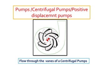
  • 1. Pumps /Centrifugal Pumps/Positive displacemnt pumps Flow through the vanes of a Centrifugal Pumps
  • 2. What are we going to discuss in Pumps, please note down so that nothing important is skipped.  See the Pumps used in a thermal power station  Purposes and classification of Pumps  Working Principle of Centrifugal, Rotary and Reciprocating pumps.  Parts and function of each  Heads acting on a centrifugal pump  NPSHr, NPSHa and Cavitation  Pumps characteristics  Series and parallel Operation
  • 3. THE PUMPS TOPIC CAN BE BROADLY CLASSIFIED INTOTWO CATEGORIES Pumps General  PUMPS USED IN ATHERMAL POWER STATION In pumps general we shall study application or usages of pumps, classification, working principle of each type of pump, details of the components, construction, different types of impellers, different types of casings, end suction, double suction, Horizontal & vertical pumps, Surface and submerged pumps, single stage and multistage pumps, Monoblock and coupled pumps, shaft sealing arrangement, Gland pacing & mechanical seal stuffing, hydraulic balancing of impellers etc.
  • 4. Head acting on a Centrifugal pump, Static suction lift, Static suction head, static lift and static head, static discharge head, Total head under different discharging conditions, Net Positive suction head, vapor pressure, frictional head loss, Velocity head, NPSHa, NPSHr and cavitations. Thermal Power Station Pumps includes: Descriptions, Design features, components, materials, location and working parameters of BFP, CEP, DRIP PUMPS, COOLING WATER PUMPS, TURBINE MAIN LUB OIL PUMP,, AC & DC Lub Oil Pumps, Ash water Pumps Slurry Pump, Chemical handling Pumps, dosing Pumps and many small lubricating Oil as positive displacement pumps.
  • 5. What Does Pumps do? Pumps utilize the input energy of a electrical motor or a diesel engine and convert it into pressure energy of the liquid so that it can be elevated from lower elevation to higher elevation as in the case of high rise buildings or from one point to another as in the case of municipal water supply system. A large number of pumps of the different types are used in every power station and a good knowledge of these hydraulic machines will help them keep running most efficiently.
  • 6. What are the Applications: Pumps can be used on clear water, lubricating oils, crude oils chemicals, pulps, slurries and almost liquid of any kind and density. Only thing required is it should be able to flow. They can also be used for creating vacuum.
  • 7. Essential data required in selection of centrifugal pump. 1. Number of units required. 2. Nature of the liquid to be Pumped. Is the liquid a. Fresh or salt water, acid or alkali, oil gasoline, slurry or paper stock b. Cold or hot and if hot what is the temperature? What is vapor pressure of the liquid at the pumping temperature? c. What is the specific gravity? d. Is it viscous or Non viscous? e. Clear and free from suspended matter, dirty or gritty? f. What is the chemical nature of the liquid, Chemical analysis and Ph value etc.
  • 8. 3. Capacity What is the required capacity as well as minimum and maximum amount of the liquid the pump will ever be called upon to deliver 4. Suction Condition. Is there a. A suction Pressure b. Or a Suction Head c. What are the length and diameter of the suction pipe 5. Discharge Conditions. a. What s static head b. What is the friction head c. What is maximum discharge pressure against which the pump must deliver the liquid.
  • 9. 6. Total Head. Variation in item 4 & 5 will cause variation in the total head. 7. Is the service continuous or intermittent? 8. Is the pump to be installed in horizontal or vertical position? Is the later in clear water or muddy liquid. 9. What type of power is available to drive the pump. What is the characteristics of the driving unit. 10.What space, weight or transportation limitations are involved.
  • 10. 10.Location of installation a. Geographical location b. Elevation above sea level c. Indoor or outdoor installation d. Range of ambient temperature 12.Are there special requirement or marked preference with reference to design , construction , sealing and performance of the pump?
  • 11. Power input :The power required to drive any class or type of the pump can be computed from P = FHS/3960E in fps Where P is the Power input, hp F liquid flow rate in gpm H =Total head on the pump in ft of the liquid handled S = Liquid specific gravity E = pump efficiency
  • 12. Head PUMP CALCULATIONS: Q xTotal Head (Hd- Hs) x d x g Hydraulic Power = ------------------------------------------ ORWHP 1000 Where: Q = Fluid Flow in meter in M 3 / Sec Hd = Discharge Head Hs = Suction Head in d = Fluid density Kg/m3 g = Acceleration due to gravity m/sec2 Hydraulic Power Pump Shaft Power Ps = -------------------------------- Pump Efficiency Pump Shaft Power Ps Electrical Motor Power = -------------------------- Motor Efficiency
  • 13. Pumps Classification PUMP Dynamic Pumps Positive Displacement pumps I I ----------------------------------- -------------------- I I I I I I Centrifugal Turbine Propeller Jet Reciprocating Rotary I I I Radial flow Single suction ------------------------------- ------------- Radial flow Double suction I I I I Mixed Flow Piston type Plunger type Diaphragm Ext. Gear Special Purpose I I I Int. GearType - ------------------------------- Sliding vane I I Screw t type Single acting Double Acting LobeType Singlex Radial Plunger Duplex Triplex Quardriplex
  • 14. • Liquid is forced into impeller • Vanes pass kinetic energy to liquid: liquid rotates and leaves impeller • Volute casing converts kinetic energy into pressure energy INTHE FIGURE IS SHOWN A RADIAL FLOW CENTRIFUGAL PUMP Working Principle of a Centrifugal Pump: Radial Flow Impeller
  • 15. One of the most commonly used type of Pump in the thermal power station is a Centrifugal Pump.  Whether the pump is a single stage or multistage pump like BFP or CEP.  Whether it is on the surface / horizontal with the shaft axis horizontal orVertical Pumps like CWP, CEP Pumps. Turbine lubricating oil pumps are also vertical pumps.  End suction or double suction like BFP, Booster pump, TGECWP, SGECWP or many other similar pumps.  Most above pumps are Centrifugal pumps, which means these pumps utilize centrifugal force by the rotating impeller, increases kinetic energy of the liquid and throw it into the volute casing. Here the Kinetic energy is converted into static pressure.
  • 16.  Another big feature of every centrifugal pumps pump is that the pump can deliver any flow from zero to 100% , rotational speed being constant.This is achieved by throttling the discharge valve.  This means that the pump can be operated to deliver any flow between zero to full flow against a specified head.  A centrifugal pump is started by closing the discharge valve and when the pump develop full shut off head or pressure the discharge valve is opened slowly and kept at the desired flow.  If the speed of the pump is changed the pump characteristics will change.  This can be understood by the figure on the next slide.
  • 17.
  • 18.
  • 19. On the other hand a positive displacement pump is entirely different from a Centrifugal pump. It delivers a fixed volume during each revolution of the rotor or the displacement of the piston in a reciprocating pump and this is dependent upon the speed of rotation. They work by trapping action. Higher the speed higher is the delivery rate lesser the speed lesser the delivery rate. Now after a positive displacement draws the fixed quantity during suction period the same is delivered during rest of the period of rotation positively.
  • 20. There is no way that the fluid can re-circulate back like centrifugal pumps.The pressure is build by the resistance the fluid encounters during flow in the delivery pipe and also by the work. Major application is in hydraulic pumps, lubricating oil pumps, fuel oil pumps.They are good for viscous liquid like lubricants.The pressure in the delivery pipe is adjusted by using a relief valve. The excess fluid flows back to suction tank. Some of the these pumps are External and internal gear type pump, Screw pumps, Sliding vane pump and many more other types.
  • 21.
  • 22.
  • 23. • Liquid is forced into impeller • Vanes pass kinetic energy to liquid: liquid rotates and leaves impeller • Volute casing converts kinetic energy into pressure energy INTHE FIGURE IS SHOWN A RADIAL FLOW CENTRIFUGAL PUMP Working Principle of a Centrifugal Pump: Radial Flow Impeller
  • 24. Components of a Centrifugal Pump
  • 25. Flow through theVolute casing of a centrifugal Pump
  • 26. CutView of a Single stage Centrifugal Pump
  • 27.  Understanding Centrifugal Pumps Nomenclature:  If the Pump is having single impeller and casing it is called single stage pump  If the pump is having more than one impeller andVolute casings or cavities or passages it is called multistage pump.  If the pump shaft is laid horizontal it is called horizontal pump.  If the pump shaft is vertical it is called vertical pump.  If the pump is laid on surface it is called surface pump.  If the pumps is lowered into water or any other liquid it is called submerged pump.  If the pump is meant for handling lubricating oil it is called lubricating oil pump.  If the pump is meant for handling slurries it is called slurry pump.  If it is for Boiler feed water application it is called Boiler feed water pump or similar.
  • 28.  If the pump is low pressure pump it is called Low pressure pump.  If the pump is meant to deliver high pressure it is called high pressure pump. Such pumps are usually multistage pump.
  • 29. A single stage end suction Centrifugal Pump
  • 30. Single or end suction Multistage Centrifugal Pump Suction Discharge Five Stage Impeller
  • 31. A single stage double suction impeller Double inlet Impeller Suction
  • 32. A more clear view of double suction impeller showing double suction impeller, Casing, water chambers, wearing ring, Shaft sealing etc.
  • 33. Actually these pump are usually multistage, vertical and submerged , they are called turbine pump due to earlier concept of turbine like arrangement, otherwise they are radial flow multistage vertical pumps. They were meant for drawing water from wells where the water level was sufficient deep. The casings are called BOWL. At the surface you will see only motor and discharge pipe. The motor shaft is coupled to the line shafts and line shafts are coupled to the pumps shafts. Some times the motor shaft is hollow and the line shaft passes through the hollow motor shaft and is coupled at the top with an arrangement of lift adjustment. The lift adjustment is required to establish the necessary running clearance between the semi open impeller and impeller seat and provide centering in case of closed impeller. The line shafts bearings can be made of bronze or rubber. Rubber bearings called CUTLLESS bearings.
  • 34. Different figures of horizontal split case radial flow centrifugal pump. It is worth noting that both suction and discharge pipes are horizontal and suction pipe is usually one pipe size bigger than the discharge. So to identify the suction and discharge is very easy. This is to keep the suction chambers flooded with water and prevent cavitation. They are normally horizontal though in vertical orientation are also available. They can be seen in every pump house . In TPS the booster pump used in the suction of BFP is this type. We can see that the shaft passes through the pump and is supported on both sides. It therefore uses two stuffing box and two bearing brackets with double row self aligning ball bearings. Gland packings in the stuffing box are cooled by the pumpage, which is a small tubing connection from the top of volute casing and attached to the stuffing box. To establish the correct direction of rotation, stand behind the motor facing the coupling, and see that it rotates towards the discharge.
  • 35. Mixed flow pumps are a mix of Pure radial flow & Pure axial flow pumps, hence application is for large flows and medium pressure. They find application in condenser cooling water circulation system, raw water system and similar application. One thing is to be noted that what ever pressure rise will be there it will be due to radial component. Radial means change in path of flow by 900 and axial flow means straight flow, therefore mix flow means combine action of radial and axial flow, which is evident from the shape of impeller, where water/liquid flows at an angle through it’s vanes and entre Volute casing which is of Bowl shape. Pump may a single or multistage, pull out or non pull out, Water lubricated or oil lubricated, gland packed or with mechanical seal etc. Impeller of a Mixed Flow Pump Entry of fluid into the eye of the impeller Impeller, Bowl, shaft & Bowl Bearing Mixed Flow Pumps Exit
  • 36. A Propeller Pump or Axial Flow Pump A propeller pump or axial flow pump will provide very large flow at very low pressure. Pressure equivalent to few meters of water column. The action of the rotating propeller is not like Radial flow impeller but like the rowing action where it only displaces the water from one side of the propeller to the other side. There is no volute case here. What ever pressure rise is there it is due to continuous propulsion. Action of propeller can be seen in the picture . To differentiate between an impeller and propeller is by looking at it’s inlet and outlet diameter they are same. In Case of an impeller the inlet is much smaller than the outlet diameter.
  • 37. These pumps are used for condenser cooling water application, dewatering or where very large flow at relatively almost negligible pressure is required. They can be seen in the pump house and are usually lowered into the water. Speeds are moderate are but specific speed is very high. They are normally very large in size and motor either 3.3KV or 6.6 KV. The shaft size may also be more than 100mm and above. Coupling used are solid flanged with a provision of lift adjustment. The stuffing box uses graphited asbestos braided packing and cooled by external water supply. Line shaft bearings are Cutless (Rubber) and pump bearings are bronze. The whole pump can be pull type and Non pull type assembly.
  • 38. Axial Flow Pump In case axial flow pumps water is simply moved upwards by the lifting actions of the vanes. In these pumps centrifugal force is zero, there is no increase in kinetic energy and hence no increase in static pressure. What ever pressure build up is there it is due to continuous propulsion of water through the discharge casing. Such pumps should be started with discharge valves in open position.
  • 39. JET PUMPS Jet Pumps are used for developing vacuum or removing air from condensers shell before start rolling turbine, work as motive power pumps to MOP ofTurbine.They have large application in mines and oil exploration. Simple in construction. No moving parts. Air or steam admission to converging nozzle may wear it’s hole size and affect the performance. Working Principle:When high pressure air or steam is admitted to the converging nozzle as motive fluid it’s velocity increases creating vacuum in the surrounding, to which if attached a suction medium will draw and carry fluid along with it to the diffuser section which is again of converging diverging nozzle.This helps the fluid drawn being forced out and a continuous process keep going.
  • 40. Different types of impellers and their applications. Open Semi Open Closed Open Impellers are used for ordinary application where pressure are low and are more suitable for not so clean water. Since the vanes are open from both sides the leakage from sides is high and therefore not suitable for high pressure. Semi open are suitable for not clear water and medium pressure application. In order to reduce leakage from the open side of the impeller a wear plate is fixed in the casing.The clearance between he open face of the impeller and face of the wear plate is maintained in order to reduce the leakage from sides of vanes. Closed impellers are having covering on both sides of the vanes called shrouds. Since there will be no leakage from sides of the vanes they are suitable for high pressure and clear water application. Almost all high pressure centrifugal pumps will have closed impellers. Whether the impeller is Radial,Axial or mixed flow all the three can be Closed, Semi Open and Open on the basis of covering ofVanes.
  • 41. Open, Semi Open and Closed Impeller Movement of fluid through Radial flow, Axial flow and Mixed flow impellers
  • 42. i i In single suction impeller the net unbalance hydraulic axial force is towards the suction and in case of double suction impeller it is cancelled out enabling the rotor to rotate in position and have almost negligible end thrust. Single end suction and Double suction impellers
  • 43. A radial flow centrifugal Pump with diffuser vane or guide ring
  • 44. Flow passage through Radial Flow, Mixed Flow and Axial Flow impellers 1. curves of Radial Flow, Mixed Flow and Axial Flow Pumps 2. Different shapes or profiles of Radial, Mixed and Axial Flow impellers.
  • 45. Application wise:  Radial Flow Impellers Centrifugal Pumps are meant for delivering not so large flow at relatively high head.  Axial Flow or Propeller Pumps are meant for delivering very large flows at very low pressure.  Mixed flow impeller Pumps are meant for delivering Medium flow at pressure less than Radial Flow but more than axial flow. Infact this can be best understood if we can understand concept of specific speed. Radial Flow impeller has low specific speed, Axial flow very high and mixed flow medium. Ns = Specific Speed Unit less NQ1/2 N is the rotational speed Ns= ---------- Q is the flow delivered in m3/s at max eff. H3/4 H is the Head developed in MWC
  • 46. Centrifugal pumps can be further differentiated based on how they direct flow. Axial flow pumps lift liquid in a direction parallel to the pump shaft.They operate essentially the same as a boat propeller. Radial flow pumps accelerate liquid through the center of the impeller and out along the impeller blades at right angles (radially) to the pump shaft. Mixed flow pumps incorporate characteristics from both axial and radial flow pumps. They push liquid out away from the pump shaft at an angle greater than 90°.
  • 47. Direction of rotation of a Centrifugal Pump Backward curved impeller
  • 48. Passage of fluid through the volute casing of Centrifugal Pump
  • 49. Backward curved vane impellers will have vane curvature opposite to the direction of rotation. Vane exit angle remain usually between 200 to 300.Why? In the expression description of various notations are: V2 = AbsoluteVelocity of fluid B2 =Vane exit angle U2 = Impeller peripheral Velocity Vr2 = Relative fluidVelocity Vf2 = Flow component of AbsoluteVelocity Vu2 =Whirl orTangential component of absoluteVelocity He = Euler Head V2 2 –V1 2 U2 2 – U1 2 Vr1 2 -Vr2 2 He = --------------- + ----------------- + -------------------- 2g 2g 2g Impeller Vane Exit Angle:
  • 50. The head developed in a rotating impeller is a combination of three distinct effects.  The term (V2 2 –V1 2)/2grepresents an increase in kinetic energy or dynamic head. Subsequent conversion of dynamic head into static pressure is achieved through retardation in the volute casing / diffuser following the impeller.  The term (U2 2 – U1 2) /2g represents an increase in static pressure accompanied within the impeller due to centrifugal force acting on the fluid ; due to movement of rotating fluid from one radius of rotation to another radius of rotation.  The term (Vr1 2 -Vr2 2)/2g represents a change in kinetic energy due to retardation of fluid flow relative to impeller; this term therefore represents, a conversion of kinetic energy within the impeller .
  • 51. Vane Shape: The shape/ form of the impeller vanes is fundamentally depending on the blade angle B2 which has a significant influence on the conversion of energy. Backward Curved : Here the outlet tips of the blades curves in the direction opposite to that of motion and the angle between the blade tip and the tangent to rotor at exit is acute (B2< 900). Radial Curved: Liquid leave the vane with relative velocity in a radial direction and B2 = 900 . Forward: Outlet tips of the blades curves in the direction of the rotation and the angle between the blade tip and the tangent to the rotor at exit is obtuse (B2> 900).
  • 52. Head Capacity Relationship: Euler’s Head He is given by:Vu2 xU2/g = U2/g(U2-Vf2cotβ2) = U2/g(U2-Q/ACotβ2) For a particular pup running at constant speed, the blade velocity U2 is fixed and and so parameter β2 and A2.Thus He = K1 – K2Q Which is straight line whose slope is fixed by angle β2 Further power developed bt is given by P = QH ; P = A’Q – B’Q For Backward CurvedVane Impeller if β2 <900 and cot β2is positive . Consequently with the increase in discharge Head capacity curve will have a negative slope. For β2 = 900 and Cot β2 = o Thus Head capacity remains constant with variation if flow. For Forward curvedVanes β2.<900 and Cot β2 is negative. Consequently with the increase in flow the head Capacity characteristic has a positive slope.
  • 53. Outlet velocity triangles for different blade settings in a centrifugal pump Β2 = Vane exit angle VW2 =Tangential components of the fluid velocity at the impeller ouutlet U2. = PeripheralVelocity of impeller at the tips Vr2 = RelativeVelocity of the fluid leaving the impeller V2 = AbsoluteVelocity of the fluid
  • 54. The head capacity characteristics of a centrifugal pump depends upon ( among other things) on the outlet angle of the impeller vane which in turn depends upon the Vane curvature. Three types of blade curvature are possible: 1) Forward curved for which the Vane curvature is in the direction of rotation and therefore β2 > 900. 2) Radial when β2 = 900. 3) Backward When β2 < 900. The outlet velocity triangle diagrams of all the three is also shown in the figure. From the geometry of any triangle the relationship betweenVW , U2 and β2 can be written as: VW2 = U2 –Vf2cot β2
  • 55.  In case of forward facing vane β2 > 900 and hence cot β2 is negative and thereforeVW2 is more than U2.  In case of radial vane β2 = 900 andVW2 = U2.  In case of backward vane β2 < 900 andVW2 < U2. and therefore sign of K2 the constant in the theoretical head capacity relationship for forward curved vane K2< 0 for radial K2 = 0 and for backward K2 > 0 Theoretical head-discharge characteristic curves of a centrifugal pump for different blade settings
  • 56. Actual head- capacity and power- capacity characteristic curves of a centrifugal pump
  • 57. Double Suction Single Stage Horizontal Centrifugal Pump:These pumps are horizontally split having stuffing box both side and essentially have double row self aligning or plain bearing. In these pumps net axial force acting on the shaft is almost reduced to zero and hence there is no need of axial load bearing and just a radial load bearing is enough. These pumps are very good as far as NPSH requirement is concerned as the suction cavities remains flooded with water. Name of the parts: 1. SplitVolute Casing 2. Double Suction Impeller 3. Pump Shaft 4. DE Bearings 5. NDE Bearing 6. Bearing Housing 7. Gland Adjusting flange 8. Stuffing Box 9. Suction Flange Suction cavity Suction Cavity Volute Cavity Pumpage
  • 58. The figure of a BHEL make Boiler feed pump for 210 Mw unit, six stages, double mechanical seal, hydraulic drum and Journal and kingsbury thrust bearing to cope with residual thrust. Suction and discharge nozzles are welded to the barrel and aligned with the flow passages. All impellers are facing suction side and volute casing is in the form of ring having a number of small volute instead of single volute. This improves the conversion from KE to static pressure and also reduces the radial reaction.
  • 59. In the figure are shown a number of wearing ring styles. They form the leakage joint diameter between the discharge to suction side and doing so it prevents short circuiting of water or system fluid from discharge side to suction side. The clearance is very important usually originally the plain bearing clearance and must be replaced if the clearance due to wear becomes double the original clearance.
  • 60. Gland packing usually braided from asbestos fibers and coated with graphite for initial lubrication A mechanical seal used in place of gland packing type stuffing box seal provides much better sealability , very less leakage and much longer seal life. A shaft sleeve to prevent direct wear of the shaft by packing rings due to friction / rubbing.
  • 61. Stuffing BoxType Seal MechanicalSeal Comparison •Jam Packing, High friction Low friction due to friction between lapped faces •Shaft/Shaft sleeve wears NoWear of Shaft sleeve due to relative motion •Continuous cooling is required Very little quantity of cooling fluid is required •Regular adjustment is required Almost no maintenance •Consumes considerable power Negligible power consumption •Not suitable for critical services Compatible for a variety of fluid •Not so skill is required Only knowledgeable skilled artisan must do it
  • 62. Mechanical Seal of Boiler feed Pump
  • 63. Self aligning Journal Bearing for radial Loads only Self aligning shell Tilting Pad trust bearing used for taking residual thrust load and assembled on Pump shaft. Thrust Collar Surge pads Thrust Pads Leveling Plates
  • 64. CUTLESS BEARING FOR LINE SHAFTS BRONZE BEARING FOR LINE SHAFTS
  • 65. BALANCINGOF AXIAL FORCE ACTING ONTHE PUMP SHAFT OR ROTOR Balancing of Axial force or thrust acing on the Pump shaft due to unequal axial force acting on suction and discharge side of the impeller. In the pump the only assembly which can axially move is the pump shaft or the rotor as the casing is fixed to the foundation or the base plate. If the net axial force acting on the pump shaft is not approximately made equal or significantly reduced the shaft will need heavy thrust bearings or heavy duty deep groove radial ball bearings to keep the shaft located.The net axial force is always in the direction of suction. There are many methods of doing this. 1. Arrange the impellers of multistage centrifugal pumps opposite to each other. 2. Use double suction pump. 3. Reduce the pressure behind the back shroud of closed impeller by drilling balancing holes and use of front and back wearing rings. 4. Use of back outVanes 5. Use of Balancing drum 6. Use of balancing disc 7. Combination of balancing drum and balancing disc
  • 66. Suction and discharge pressure Acting on the front & back shroud of an impeller When a wearing ring is used at the front shroud (Suction side) It seals the discharge pressure leaking back to suction through the running clearance. The above figure shows the unbalance force remains and acting on the back shroud and towards the suction.
  • 67. Drilling a balancing hole in the back shroud and providing wearing rings at both suction and discharge sides, will connect the area ‘B’ with the suction. The holes will bleed the leaked water from discharge wearing ring back into suction eye thus keeping the pressure behind the impeller almost equal to suction pressure and cancels out the hydraulic force acting on area “A”. Hence unbalance force on the back shroud as seen in the previous figure will get balanced to a great extent. Using pumpout vanes at the back shroud will reduce pressure behind the impeller and therefore the unbalance force.
  • 68. In the figure is shown an arrangement of Balancing drum fixed on the shaft which rotates in balancing drum guide. The clearance between the guide and drum being small, it throttles the discharge pressure to the calculated balancing chamber pressure. Our purpose is to balance the unbalance force acting on area ‘A’. Now look at the front area ‘B’ of the drum and rear area ‘C’ which are so calculated that Discharge pressure x area “B” equals the unbalance area of Impeller. Unbalance Area “A” x Suction pressure is equaled by Balancing chamber pressure x area “C” The balancing chamber is connected to the suction of the pump and it’ s pressure can be regulated with the help of a valve so that pressure unbalance axial force is almost cancelled. Balancing drum Balancing drum guide bush
  • 69. Balancing Disc arrangement of balancing hydraulic unbalance force acting on impeller.
  • 70. Combination of Balancing Drum and balancing Disc for hydraulic balancing of Unbalance axial force in case of multistage centrifugal pumps.
  • 71.
  • 72.
  • 73.
  • 74. Picture of a large centrifugal Pump How to see the direction of Rotation Volute casing Stand behind the motor and coupling should rotate towards the Come discharge or progressing volute casing.
  • 75.
  • 77.
  • 79.
  • 81.
  • 82. Axial Piston Type Reciprocating Pump
  • 83.
  • 85. ROTARY – PUMP CHARACTERISTICS Neglecting leakage rotary pumps deliver almost constant capacity against variable discharge pressure. So the usual HQ cure is nearly a horizontal line. Displacement of a rotary pump varies directly as the speed, except as the capacity may be affected by viscosity and other factors. Thick viscous liquid may limit the pumps capacity at higher speed s because the liquid cannot flow into the casing rapidly enough to fill it completely. The slip or loss in capacity through clearances between the casing and rotating element, assuming a constant viscosity, varies as the discharge pressure increases. For example in the next slide at 600 rpm and 0 psi discharge pressure , capacity is 108 gpm. But at 300 psi and the same speed the capacity is 92 gpm.The difference of 16 gpm is slip or loss. Power input to a rotary pump: HQ characteristic curve , increases with the liquid viscosity. Efficiency decreases with the rise in viscosity
  • 86. All rotary Pumps are positive displacement pumps:  By this we mean all these pumps, rotor draw and trap a certain volume of liquid during the suction period and carry the same along and inside the casing to push it out through the discharge port. Most of these pumps handle viscous liquids. The clearances in the casing everywhere should remain sealed either with the help of pumping fluid itself or suitable lubricant.They all require priming before starting.  The discharge valve should be ensured to be open before starting otherwise the pumps casing damage immediately on starting.  To prevent the accidental damage due to closure of the discharge valve while running and also if the load on the pump is high, a relief valve is provided in the casing towards discharge side or in the discharge side immediately after the pump. This will relieve the excess pressure back to suction tank or suction side.
  • 87. Positive Displacement and Centrifugal technologies have operating characteristics that are very different. At constant speed centrifugal pumps deliver a variable volume of liquid while positive displacement pumps deliver a constant volume. There are applications that clearly should be positive displacement and applications that are clearly centrifugal. However, there is a broad envelope of applications where both types should be considered based on the requirements and desired performance results.
  • 90. CrossectionalView of a Canned Rotor Pump
  • 91. Very Important to Understand: Each pump has its own operating characteristics that limits its application. For example in a centrifugal pumps small change in pressure differential will cause relatively larger change in flow. On the other hand a rotary pump will deliver an almost constant quantity regardless of pressure fluctuations.
  • 92.
  • 93.
  • 94.
  • 95.
  • 96.  h - progressively falls with increasing flow rate - q. Stable Head Flow Characteristics
  • 97. falls falls falls falls •increasing flow rate - q. - h - rises to a maximum and then progressively falls with Unstable Head-flow Characteristics
  • 98. Relationship between various pressure terms used in Pumping Any Pressure above atmospheric Gauge Pressure Barometric Pressure Atmospheric pressure vacuum Absolute pressure Any Pressure below atmospheric Absolute Zero Absolute pressure = gage + barometric
  • 99. Pressure: three pressure terms commonly arise in pumping problems – absolute , gage pressure , barometric, and forth vacuum. Absolute pressure: Absolute pressure is the pressure above zero. It may be above or below the atmosphere pressure at the point under consideration. Barometric Pressure: Barometric pressure is the atmospheric pressure at the locality being studied and varies with the altitude and climatic condition. Gauge Pressure: gage pressure is the pressure above atmospheric at the locality where it is measured. Vacuum: A vacuum is the negative gage pressure.
  • 100. Head: A column of water or any other liquid in a vertical pipe exerts a certain pressure ( force per unit area ) n the horizontal surface at the bottom of the pipe. The pressure can be expressed in pounds per square inch, kilogram per square inch or number of feet or meter of liquid which would exert an equal pressure on the surface . The height of the column of liquid producing the same pressure is known as head on the surface. Approximately 1 kg/cm2 = 14.7 psi = 10 meter = 34 ft = 760mm of hg. So equivalents can be calculated.
  • 101. Head: A Column of water or other liquid in a vertical pipe exerts a certain pressure (force per unit area) on the horizontal surface at the bottom of the pipe. The pressure can be expressed in PSI, Kg/Cm2 , feet of water. The height of the column of liquid producing the pressure in question is known as head on the surface. 14.7 psi = 1 kg/cm2 = 1 bar = 34’ of water column = 10 meter of water column = 760mm of Hg column. All approximately.One can easily equate now.
  • 102. Static Head: In pumping application the height of the liquid column acting on the pump suction or discharge is often termed the static head on liquid. Static head is the difference in elevation from the free surface of the liquid to that of the pump centre line. Terms Used in Pumping
  • 103. Total Suction Lift: Static Suction lift + Suction frictional head + Entrance losses + SuctionVelocity head. HS= hS + hF + hE +V2/29 Total Discharge Head: HD = hd + hF + hO +V2/29 Net Positive Suction Head: The manufacturer will provide the information that so and so pump to deliver a certain quantity and operating at required efficiency should be installed with certain minimum required pressure at pump inlet so that the pump does its intended work. If this minimum pressure required at the pump inlet is not established the pump may cavitate subsequently either partially stopping or fully stopping the flow of liquid into impeller eye. So there are two terms:
  • 104. NET POSITIVE SUCTION HEAD REQUIRED: This is provided by the Pumps manufacturer and depends upon impeller design, it’s diameter, no of vanes, passage through vanes, vanes curvature etc. NET POSITIVE SUCTION HEAD AVAILABLE: This depends upon layout of suction pipe line, diameter of the suction pipe, resistance in the suction pipe line, diameter of the impeller eye and location of the pump.
  • 105. Now that available NPSH is in our hand or in other words we should install the pump with either suction lift or suction head so that available NPSH is always more than required NPSH by about 25%. Avail able NPSH = HAP ± (HS+Hf +HE+V2/2g+HVP) OR P+ HS -- (Hf +HE+V2/2g+HVP)
  • 106. Vapor Pressure: Every liquid at any temperature above its freezing point exerts a pressure due to formation of vapors at its free surface. This pressure is known as Vapor pressure of the liquid and is a function of the temperature of the liquid. The higher the temperature of the liquid, the higher the vapor pressure. Vapor pressure is an important factor in the suction condition of pump handling liquids of all types. In any pumping system the pressure at any point should never be reduced below vapor pressure corresponding to the temperature of he liquid because the liquid will form vapor which will partially or completely stop liquid flow into the pump.
  • 107. Cavitation in centrifugal pumps: Cavitation is a common occurrence but is the least understood of all pumping problems. Your pump is cavitating if knocking noises and vibrations can be heard when it is operating. Other signs may be erratic power consumption and fluctuations or reductions in pump output. If you continue to operate your pump when it is cavitating, it will be damaged. Impeller surfaces and pump bowls will pit and wear, eventually leading to mechanical destruction.
  • 108. What is the cause of Cavitation: When water enters a pump, its velocity increases causing a reduction in pressure within the pumping unit. If this pressure falls too low, some of the water will vaporize, forming bubbles entrained in the liquid. These bubbles collapse violently as they move to areas of higher pressure creating the noise and vibration from the pump. The pressure required to operate a pump without causing cavitation is called net positive suction head (NPSH). Therefore the pressure head available at the pump inlet should exceed the NPSH required. This is specified by the pump manufacturer, and is a function of the pump design
  • 109. How to avoid cavitation : As cavitation relates only to the suction side of the pump. All prevention measures should be directed at this area. Suction lifts that are too high will only encourage cavitation. As a general rule, centrifugal pumps located less than 4 meters above the water level should not experience cavitation Cavitation effect on the underside of the vanes of the impeller
  • 110. The following guidelines should be applied to avoid the problem of Cavitation: • minimize the number of valves and bends in the suction line • use eccentric reducers, not concentric • ensure the straight side of the eccentric reducer is installed along the top of the suction line • suction length should be as short as possible • suction pipe should be at least the same diameter as the pump inlet connection • use long radius bends • increase the size of valves and pipe work • do not allow air into the suction line • ensure adequate submergence over the foot valve. The submergence should be at least 5.3 times the suction diameter.
  • 111. Alternative solutions : One solution may be to reduce the required net positive suction head. This can done by lowering the pump speed. However, this will also result in reduced output from the pump which may not suit your system. If pump suction conditions cannot be improved, you should seek expert assistance. It may be that your pumping system needs to be redesigned. Assistance Your local office of the Department of Natural Resources and Water may be able to assist you further with this topic or water supply, irrigation or drainage generally. Call them for details of other fact sheets, available services and associated charges.
  • 112. Pumps in Serial - Head Added When two (or more) pumps are arranged in series their resulting pump performance curve is obtained by adding their heads at the same flow rate. Centrifugal pumps in series are used to overcome larger system head loss than one pump can handle alone. for two identical pumps in series the head will be twice the head of a single pump at the same flow rate - as indicated in point 2. With a constant flow rate the combined head moves from 1 to 2. point 3 is where the system operates with both pumps running point 1 is where the system operates with one pump running Series operation of single stage pumps is seldom encountered - more often multistage centrifugal pumps are used. Two Pumps operated in Series
  • 113. Two Pumps in parallel operation Pumps in Parallel - Flow Rate Added When two or more pumps are arranged in parallel their resulting performance curve is obtained by adding their flowrates at the same head as indicated in the figure below. Centrifugal pumps in parallel are used to overcome larger volume flows than one pump can handle alone. for two identical pumps in parallel, and the head is kept constant, the flowrate doubles as indicated with point 2 compared to a single pump Note! In practice the combined head and volume flow moves along the system curve as indicated from 1 to 3. point 3 is where the system operates with both pumps running point 1 is where the system operates with one pump running In practice, if one of the pumps in parallel or series stops, the operation point moves along the system resistance curve from point 3 to point 1 - the head and flow rate are decreased.