Downloaded 402 times
![References
"Pressure Relief Valve Sizing Calculations". (2017). Pressure Relief Valve Sizing Calculations – Subcritical Gas
Flow Service. Retrieved January 12, 2017, from Engcyclopedia: http://www.enggcyclopedia.com/2011/11/pressure-
relief-valve-sizing-calculations-subcritical-gas-flow/
API. (2013, December). API Standard 520 Part 1. Sizing, Selection, and Installation of Pressure-relieving Devices,
9th. Washington, D.C: American Petroleum Institute.
Coker, A. K. (2006). Process Safety and Pressure-Relieving Devices. In Applied Process Design for Chemicals and
Petrochemical Plants (4th ed., pp. 575-578). Oxford, 1: Gulf Professional Publishing.
Coker, A. K. (2006). Process Safety and Pressure-Relieving Devices. In Applied Process Design for Chemical and
Petrochemicals (4th ed., p. 580). Oxford: Gulf Professional Publishing.
Crowl, D. A., & Tipler, S. A. (2013, October). Sizing Pressure-Relief Devices. Chemical Engineering Progress, pp.
68-76.
Gas flow through nozzles - sonic chokes. (n.d.). The Engineering ToolBox. Retrieved January 18, 2017, from
Nozzles: Gas flow through nozzles - sonic chokes: http://www.engineeringtoolbox.com/nozzles-d_1041.html
Hellemans, M. (2009). Terminology. In The Safety Relief Valve handbook: Design and Use of Process Safety
Valves to ASME and International Codes and Standards (1st ed., p. 44). Burlington: Butterworth-Heinemann.
Hellemans, M. (2009). Terminology. In The Safety Relief Valve Handbook: Design and Use of Process Safety
Valves to ASME and International Codes and Standards (1st ed., pp. 34-35). Burlington: Butterworth-Heinemann.
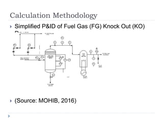
MOHIB. (2016, October 9). CHEMEWORK. Retrieved January 13, 2017, from FRESH WATER AND FUEL GAS
SYSTEM [Blog post]: http://www.chemework.com/2016/10/09/fresh-water-and-fuel-gas-system/
Triyanto SR. (n.d.). Process Engineer. Retrieved December 26, 2016, from Built Up and Superimpossed Back
Pressure [Blog post]: http://process-eng.blogspot.my/2011/02/built-up-and-superimposed-back-pressure_2304.html
Triyanto SR. (n.d.). Process Engineer. Retrieved January 1, 2017, from Accumulation and Overpressure [Blog
post]: http://process-eng.blogspot.my/2012/03/accumulation-and-overpressure.html
Whitesides, R. W. (2008). PDH Course M112: Selection and Sizing of Pressure Relief Valves. PDHOnline.](https://image.slidesharecdn.com/single-phaseprvsizing-170312021925/85/Pressure-Relief-Valve-Sizing-for-Single-Phase-Flow-25-320.jpg)

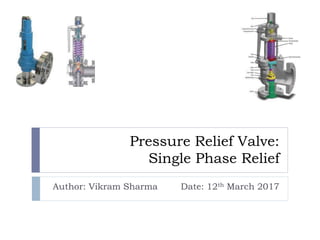
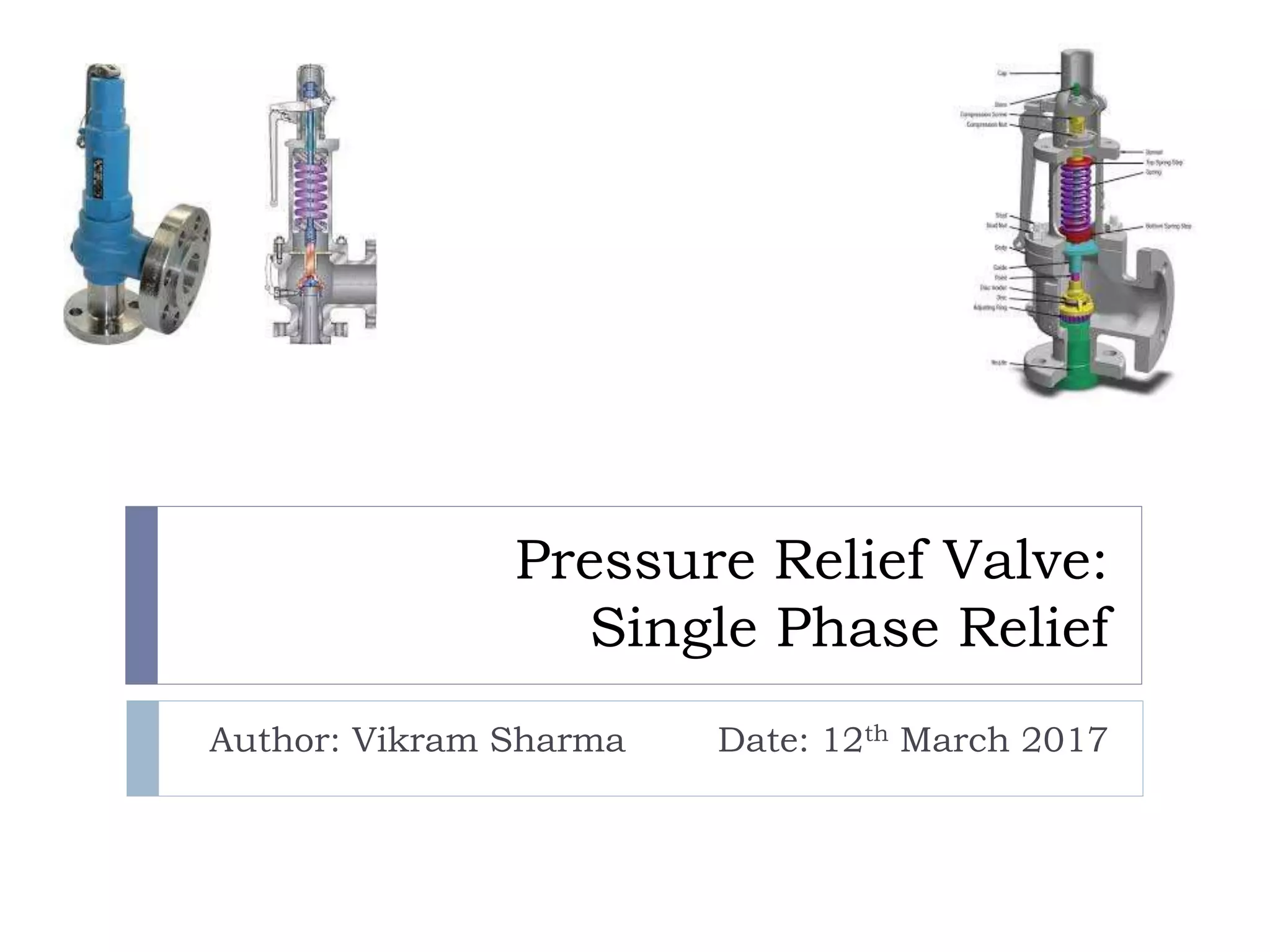
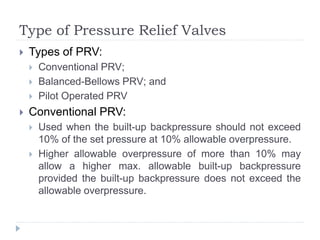
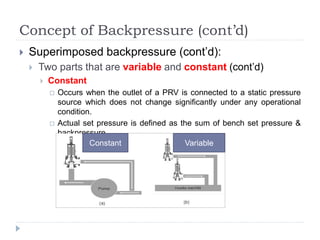
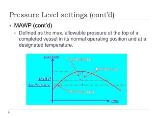
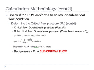
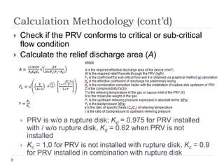
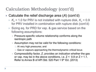
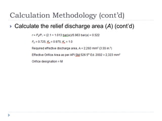
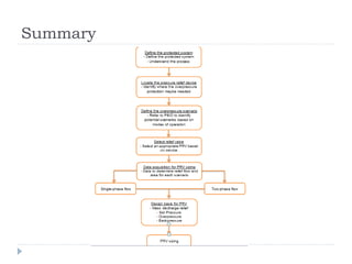
This document provides an in-depth overview of pressure relief valves (PRVs), including types such as conventional, balanced-bellows, and pilot-operated PRVs, as well as the concepts of backpressure and pressure level settings. It details the calculation methodologies according to API standards for sizing and selecting PRVs to ensure safety against overpressure. The document also clarifies definitions of key terms such as set pressure, accumulation, and maximum allowable working pressure (MAWP).


