Downloaded 251 times
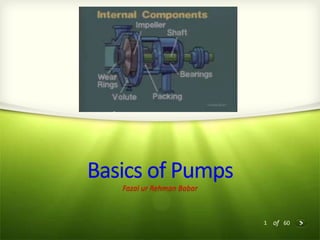
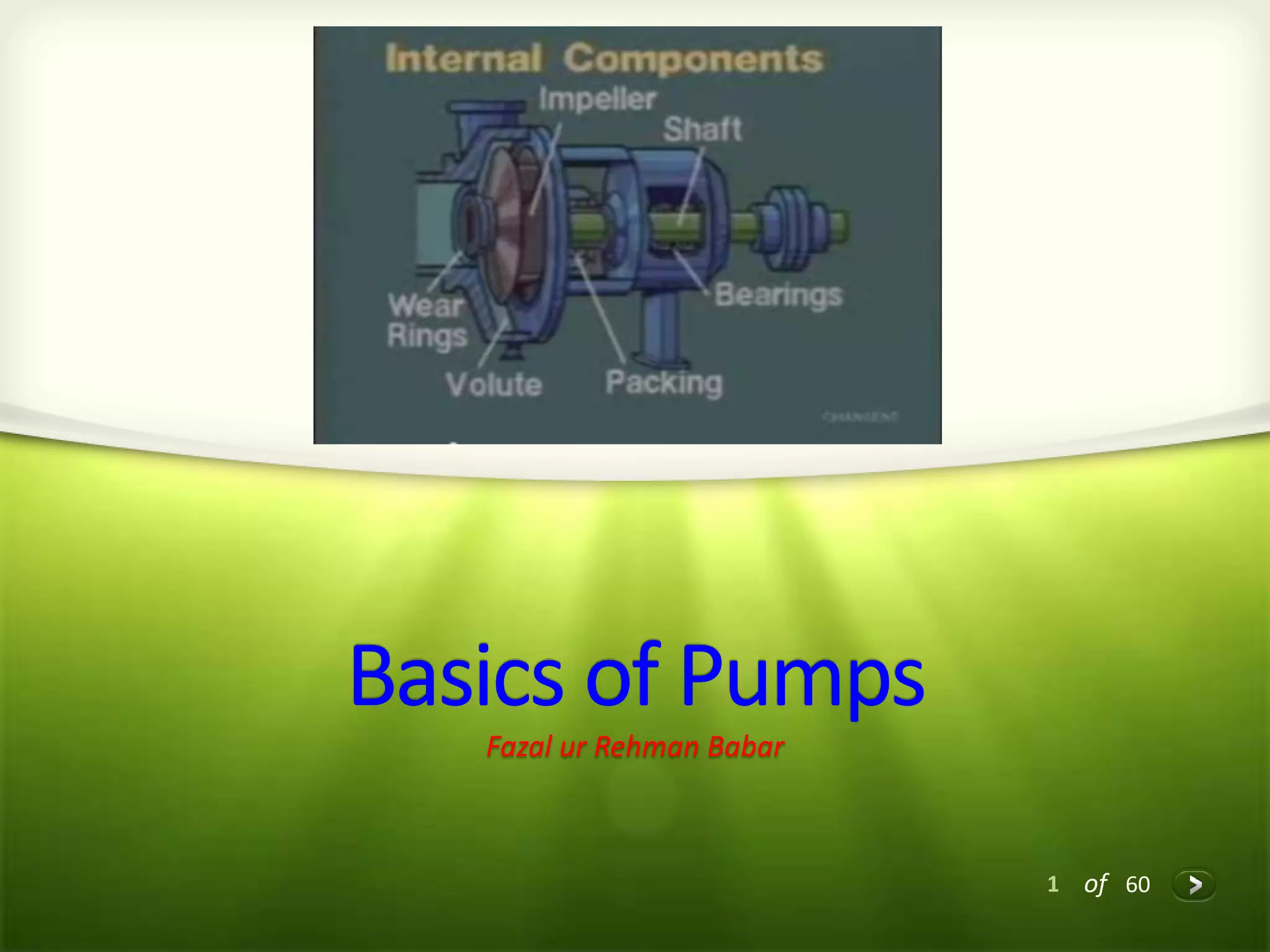
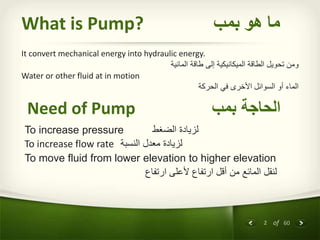
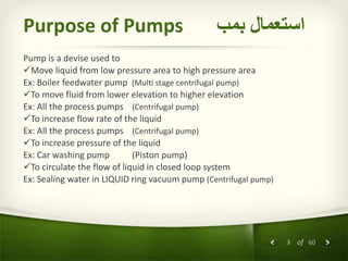

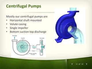
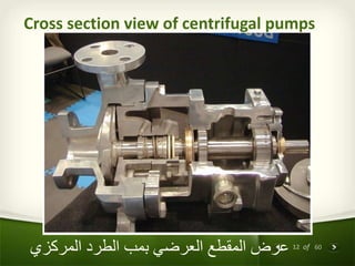
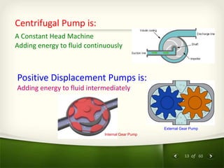
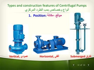
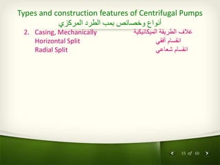
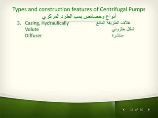
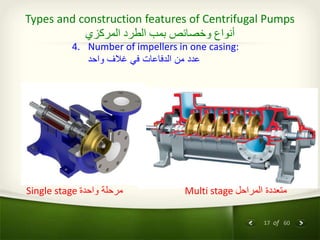
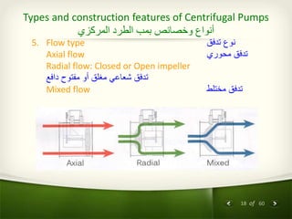
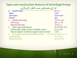
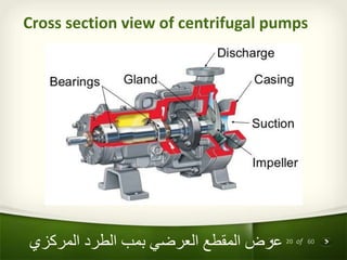
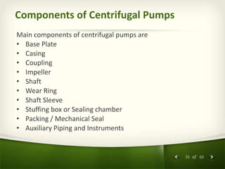
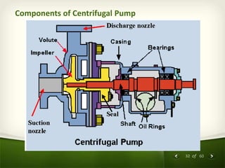
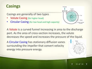
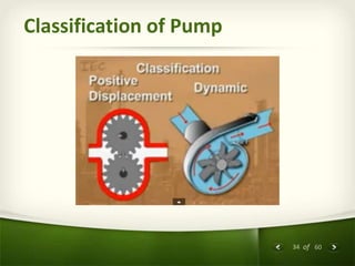
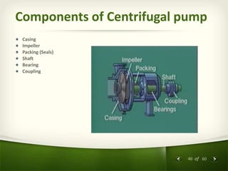
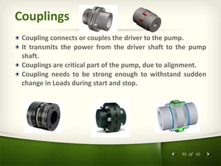
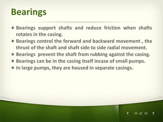

The document provides an overview of centrifugal pumps. It defines what a pump is and explains that a centrifugal pump works by using centrifugal force to increase the pressure of a fluid. The key components of a centrifugal pump are then described in detail, including the casing, impeller, shaft, couplings, and bearings. Different types of impellers and casings are also discussed.


