Downloaded 426 times


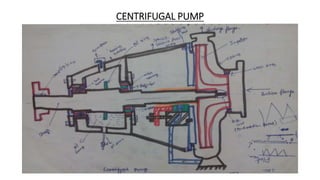


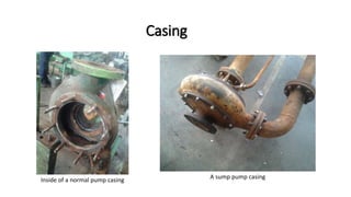
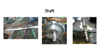

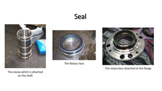


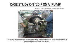


This document summarizes a presentation given by Vaibhav Kumar Arya on vocational training at Bharat Petroleum Corporation Limited in Mumbai. It discusses BPCL's refineries and history. It then focuses on centrifugal pumps, describing their main components and providing a case study on disassembling, cleaning, inspecting and reassembling a specific pump model. The pump was taken apart to replace a leaking mechanical seal and other worn parts.


![Centrifugal+Pump+Main[1].+Seminar+(Tt$)](https://cdn.slidesharecdn.com/ss_thumbnails/centrifugalpumpmain1seminartt-1229019365042251-1-thumbnail.jpg?width=640&height=640&fit=bounds)


