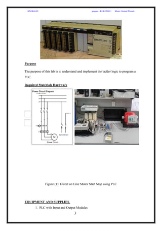
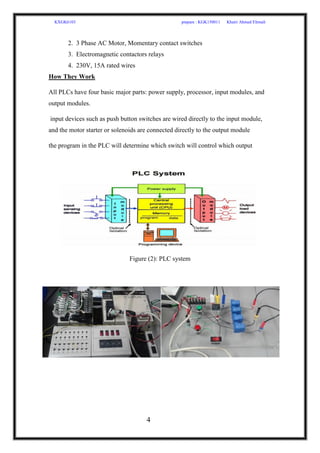
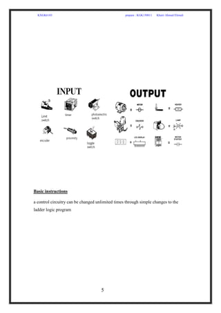
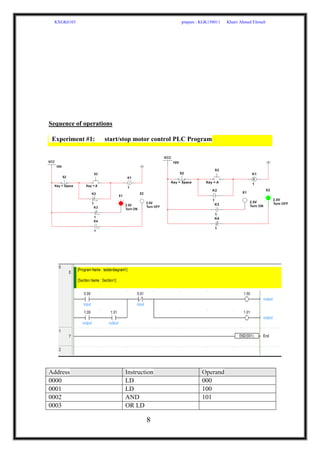
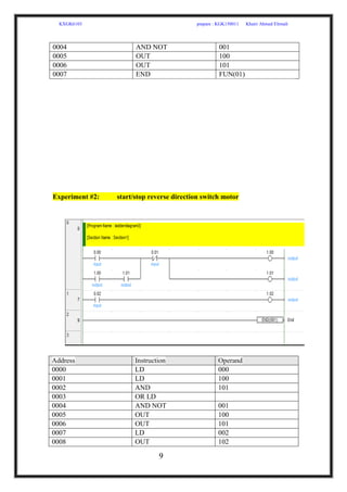
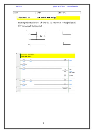
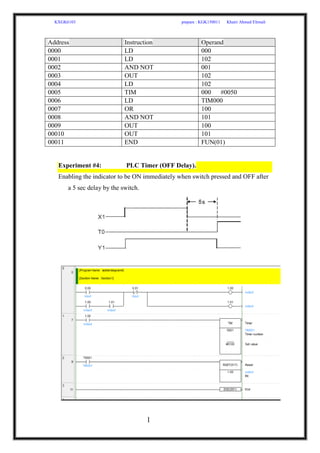
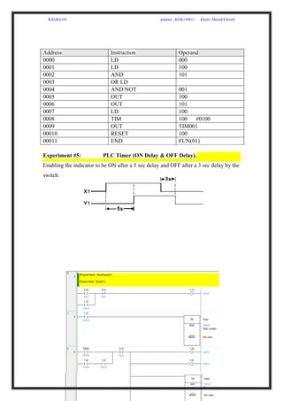
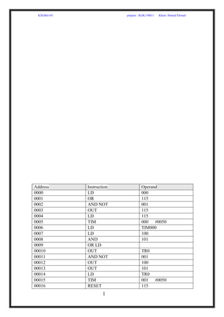
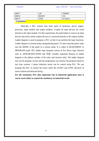
KXGK6103 prepare : KGK150011 Khairi Ahmed Elrmali
1
FACULTY OF ENGINEERING
(INDUSTRIAL ELECTRONIC AND CONTROL)
MODERN INDUSTRIAL ELECTRONICS
(KXGK6103)
Laboratory #1
Basic PLC Ladder Programming
KGK150011
Khairi Ahmed Elrmali
KXGK6103 prepare : KGK150011 Khairi Ahmed Elrmali
2
Submitted To: Professor Dr. Saad Mekhilef
Semester I
Academic Session 2016/2017
Introduction
Overview
A programmable logic controller, also called a “PLC” or “programmable controller”,
is a computer – type device often used to control equipment in an industrial facility.
The kinds of equipment that PLCs can control are numerous. Conveyor systems, food
processing machinery, and auto assembly lines are all controlled by PLCs
PLC brands: Siemens, Allen-Bradley, IDEC, ABB, Mitsubishi, Omron, Honeywell,
Schneider Electric, Saia-Burgess Controls, and General Electric.
In this experiment we will use Omron (SYSMAC C200HS OMRON)
KXGK6103 prepare : KGK150011 Khairi Ahmed Elrmali
3
Purpose
The purpose of this lab is to understand and implement the ladder logic to program a
PLC.
Required Materials Hardware
Figure (1): Direct on Line Motor Start Stop using PLC
EQUIPMENT AND SUPPLIES
1. PLC with Input and Output Modules
KXGK6103 prepare : KGK150011 Khairi Ahmed Elrmali
4
2. 3 Phase AC Motor, Momentary contact switches
3. Electromagnetic contactors relays
4. 230V, 15A rated wires
How They Work
All PLCs have four basic major parts: power supply, processor, input modules, and
output modules.
input devices such as push button switches are wired directly to the input module,
and the motor starter or solenoids are connected directly to the output module
the program in the PLC will determine which switch will control which output
Figure (2): PLC system
KXGK6103 prepare : KGK150011 Khairi Ahmed Elrmali
5
Basic instructions
a control circuitry can be changed unlimited times through simple changes to the
ladder logic program
KXGK6103 prepare : KGK150011 Khairi Ahmed Elrmali
6
Lab Procedure
The programming panel can be a dedicated device or it can be a personal or
portable computer with PLC programming software loaded on it
KXGK6103 prepare : KGK150011 Khairi Ahmed Elrmali
7
PROGRAM: to make or modify or improve the program.
MONITOR: to change the value of the counter and timer settings when the PLC still
operate
RUN: to operate the PLC without being able to change the value of the existing
settings
Procedure to insert the program
KXGK6103 prepare : KGK150011 Khairi Ahmed Elrmali
8
Sequence of operations
Experiment #1: start/stop motor control PLC Program
Address Instruction Operand
0000 LD 000
0001 LD 100
0002 AND 101
0003 OR LD
KXGK6103 prepare : KGK150011 Khairi Ahmed Elrmali
9
0004 AND NOT 001
0005 OUT 100
0006 OUT 101
0007 END FUN(01)
Experiment #2: start/stop reverse direction switch motor
Address Instruction Operand
0000 LD 000
0001 LD 100
0002 AND 101
0003 OR LD
0004 AND NOT 001
0005 OUT 100
0006 OUT 101
0007 LD 002
0008 OUT 102
KXGK6103 prepare : KGK150011 Khairi Ahmed Elrmali
1
0
0009 END FUN(01)
Experiment #3: PLC Timer (ON Delay).
Enabling the indicator to be ON after a 3 sec delay when switch pressed and
OFF immediately by the switch .
KXGK6103 prepare : KGK150011 Khairi Ahmed Elrmali
1
1
Experiment #4: PLC Timer (OFF Delay).
Enabling the indicator to be ON immediately when switch pressed and OFF after
a 5 sec delay by the switch.
Address Instruction Operand
0000 LD 000
0001 LD 102
0002 AND NOT 001
0003 OUT 102
0004 LD 102
0005 TIM 000 #0050
0006 LD TIM000
0007 OR 100
0008 AND NOT 101
0009 OUT 100
00010 OUT 101
00011 END FUN(01)
KXGK6103 prepare : KGK150011 Khairi Ahmed Elrmali
1
2
Address Instruction Operand
0000 LD 000
0001 LD 100
0002 AND 101
0003 OR LD
0004 AND NOT 001
0005 OUT 100
0006 OUT 101
0007 LD 100
0008 TIM 100 #0100
0009 OUT TIM001
00010 RESET 100
00011 END FUN(01)
Experiment #5: PLC Timer (ON Delay & OFF Delay).
Enabling the indicator to be ON after a 5 sec delay and OFF after a 3 sec delay by the
switch.
KXGK6103 prepare : KGK150011 Khairi Ahmed Elrmali
1
3
Address Instruction Operand
0000 LD 000
0001 OR 115
0002 AND NOT 001
0003 OUT 115
0004 LD 115
0005 TIM 000 #0050
0006 LD TIM000
0007 LD 100
0008 AND 101
0009 OR LD
00010 OUT TR0
00011 AND NOT 001
00012 OUT 100
00013 OUT 101
00014 LD TR0
00015 TIM 001 #0050
00016 RESET 115
KXGK6103 prepare : KGK150011 Khairi Ahmed Elrmali
1
4
00017 LD TIM001
00018 RESET 101
00019 END FUN(01)
Conclusion
Basically a PLC contain four basic parts of hardware: power supply,
processer, input module and output modules. Usually all input devices are wired
directly to the input module. For this experiments, the push button is used as an input
devices and motor starter (output devices) is connected directly to the output module.
Ladder diagram is used to program a PLC so that it can perform the logic functions.
Ladder diagram is created using a programming panel. To start using the panel, make
sure the MODE of the panel in a correct mode. It is either in READ,WRITE or
PROGRAM mode. PLC ladder logic program consist of five basics logic function
such as AND,OR,NOT,NAND and NOR. Another important features in ladder
diagram is the address number of the relay and memory relay. The ladder diagram
also can be program on-line and the programmer can monitor the program based on
real time systems. 3 phase induction motor can be control using PLC. We can
program the PLC to control the motor either the START and STOP, direction of
motor rotation and delayed timing .
For the conclusion, PLC play important role in industrial application since it
can be used widely to control the machinery in industrial world

Basic PLC Ladder Programming

  • 1.
    KXGK6103 prepare :KGK150011 Khairi Ahmed Elrmali 1 FACULTY OF ENGINEERING (INDUSTRIAL ELECTRONIC AND CONTROL) MODERN INDUSTRIAL ELECTRONICS (KXGK6103) Laboratory #1 Basic PLC Ladder Programming KGK150011 Khairi Ahmed Elrmali
  • 2.
    KXGK6103 prepare :KGK150011 Khairi Ahmed Elrmali 2 Submitted To: Professor Dr. Saad Mekhilef Semester I Academic Session 2016/2017 Introduction Overview A programmable logic controller, also called a “PLC” or “programmable controller”, is a computer – type device often used to control equipment in an industrial facility. The kinds of equipment that PLCs can control are numerous. Conveyor systems, food processing machinery, and auto assembly lines are all controlled by PLCs PLC brands: Siemens, Allen-Bradley, IDEC, ABB, Mitsubishi, Omron, Honeywell, Schneider Electric, Saia-Burgess Controls, and General Electric. In this experiment we will use Omron (SYSMAC C200HS OMRON)
  • 3.
    KXGK6103 prepare :KGK150011 Khairi Ahmed Elrmali 3 Purpose The purpose of this lab is to understand and implement the ladder logic to program a PLC. Required Materials Hardware Figure (1): Direct on Line Motor Start Stop using PLC EQUIPMENT AND SUPPLIES 1. PLC with Input and Output Modules
  • 4.
    KXGK6103 prepare :KGK150011 Khairi Ahmed Elrmali 4 2. 3 Phase AC Motor, Momentary contact switches 3. Electromagnetic contactors relays 4. 230V, 15A rated wires How They Work All PLCs have four basic major parts: power supply, processor, input modules, and output modules. input devices such as push button switches are wired directly to the input module, and the motor starter or solenoids are connected directly to the output module the program in the PLC will determine which switch will control which output Figure (2): PLC system
  • 5.
    KXGK6103 prepare :KGK150011 Khairi Ahmed Elrmali 5 Basic instructions a control circuitry can be changed unlimited times through simple changes to the ladder logic program
  • 6.
    KXGK6103 prepare :KGK150011 Khairi Ahmed Elrmali 6 Lab Procedure The programming panel can be a dedicated device or it can be a personal or portable computer with PLC programming software loaded on it
  • 7.
    KXGK6103 prepare :KGK150011 Khairi Ahmed Elrmali 7 PROGRAM: to make or modify or improve the program. MONITOR: to change the value of the counter and timer settings when the PLC still operate RUN: to operate the PLC without being able to change the value of the existing settings Procedure to insert the program
  • 8.
    KXGK6103 prepare :KGK150011 Khairi Ahmed Elrmali 8 Sequence of operations Experiment #1: start/stop motor control PLC Program Address Instruction Operand 0000 LD 000 0001 LD 100 0002 AND 101 0003 OR LD
  • 9.
    KXGK6103 prepare :KGK150011 Khairi Ahmed Elrmali 9 0004 AND NOT 001 0005 OUT 100 0006 OUT 101 0007 END FUN(01) Experiment #2: start/stop reverse direction switch motor Address Instruction Operand 0000 LD 000 0001 LD 100 0002 AND 101 0003 OR LD 0004 AND NOT 001 0005 OUT 100 0006 OUT 101 0007 LD 002 0008 OUT 102
  • 10.
    KXGK6103 prepare :KGK150011 Khairi Ahmed Elrmali 1 0 0009 END FUN(01) Experiment #3: PLC Timer (ON Delay). Enabling the indicator to be ON after a 3 sec delay when switch pressed and OFF immediately by the switch .
  • 11.
    KXGK6103 prepare :KGK150011 Khairi Ahmed Elrmali 1 1 Experiment #4: PLC Timer (OFF Delay). Enabling the indicator to be ON immediately when switch pressed and OFF after a 5 sec delay by the switch. Address Instruction Operand 0000 LD 000 0001 LD 102 0002 AND NOT 001 0003 OUT 102 0004 LD 102 0005 TIM 000 #0050 0006 LD TIM000 0007 OR 100 0008 AND NOT 101 0009 OUT 100 00010 OUT 101 00011 END FUN(01)
  • 12.
    KXGK6103 prepare :KGK150011 Khairi Ahmed Elrmali 1 2 Address Instruction Operand 0000 LD 000 0001 LD 100 0002 AND 101 0003 OR LD 0004 AND NOT 001 0005 OUT 100 0006 OUT 101 0007 LD 100 0008 TIM 100 #0100 0009 OUT TIM001 00010 RESET 100 00011 END FUN(01) Experiment #5: PLC Timer (ON Delay & OFF Delay). Enabling the indicator to be ON after a 5 sec delay and OFF after a 3 sec delay by the switch.
  • 13.
    KXGK6103 prepare :KGK150011 Khairi Ahmed Elrmali 1 3 Address Instruction Operand 0000 LD 000 0001 OR 115 0002 AND NOT 001 0003 OUT 115 0004 LD 115 0005 TIM 000 #0050 0006 LD TIM000 0007 LD 100 0008 AND 101 0009 OR LD 00010 OUT TR0 00011 AND NOT 001 00012 OUT 100 00013 OUT 101 00014 LD TR0 00015 TIM 001 #0050 00016 RESET 115
  • 14.
    KXGK6103 prepare :KGK150011 Khairi Ahmed Elrmali 1 4 00017 LD TIM001 00018 RESET 101 00019 END FUN(01) Conclusion Basically a PLC contain four basic parts of hardware: power supply, processer, input module and output modules. Usually all input devices are wired directly to the input module. For this experiments, the push button is used as an input devices and motor starter (output devices) is connected directly to the output module. Ladder diagram is used to program a PLC so that it can perform the logic functions. Ladder diagram is created using a programming panel. To start using the panel, make sure the MODE of the panel in a correct mode. It is either in READ,WRITE or PROGRAM mode. PLC ladder logic program consist of five basics logic function such as AND,OR,NOT,NAND and NOR. Another important features in ladder diagram is the address number of the relay and memory relay. The ladder diagram also can be program on-line and the programmer can monitor the program based on real time systems. 3 phase induction motor can be control using PLC. We can program the PLC to control the motor either the START and STOP, direction of motor rotation and delayed timing . For the conclusion, PLC play important role in industrial application since it can be used widely to control the machinery in industrial world