Outline
Review briefhistory of PLCs and manufacturing control
systems
Introduce the concepts of discrete control of
manufacturing
To define the basic components of a PLC
define the basic Architecture of a PLC
Review the various kinds of instrumentation used for
control.
Overview ladder logic programming
3.
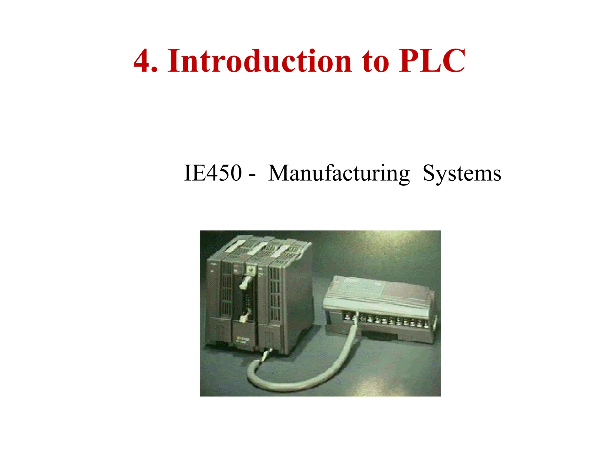
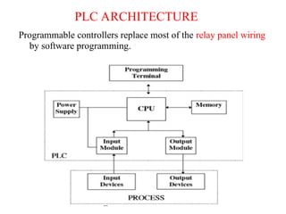
PROGRAMMABLE LOGIC CONTROLLER(PLC)
• Invented in 1968 as a substitute for hardwired relay panels.
‘National Electrical Manufacturing Association (NEMA)’
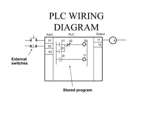
• "A digitally operating electronic apparatus which uses a
programmable memory for the internal storage of instructions by
implementing specific functions; such as logic sequencing, timing,
counting, and arithmetic to control, through digital or analog
input/output modules, various types of machines or processes.
• The digital computer which is used to perform the functions of a
programmable controller is considered to be within this scope.
• Excluded are drum and other similar mechanical sequencing
controllers."
4.
purpose of ProgrammableLogic Controllers (PLCs)
• Initially designed to replace relay logic boards
– Sequence device actuation
– Coordinate activities
• Accepts input from a series of switches
• Sends output to devices or relays
5.
FUNCTIONS OF CONTROLLERS
•1) on-off control,
• 2) sequential control,
• 3) feedback control, and
• 4) motion control.
6.
CONTROL DEVICES
1) mechanicalcontrol - governor
2) pneumatic control - compressed air, valves, etc.
3) electromechanical control - switches, relays, a timer,
counters, etc,
4) electronics control - similar to electromechanical
control, except uses electronic switches.
5) computer control.
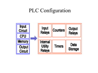
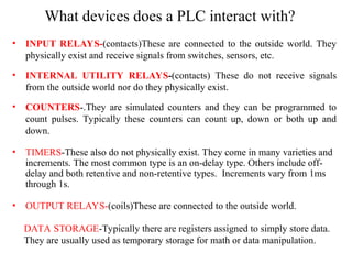
What devices doesa PLC interact with?
• INPUT RELAYS-(contacts)These are connected to the outside world. They
physically exist and receive signals from switches, sensors, etc.
• INTERNAL UTILITY RELAYS-(contacts) These do not receive signals
from the outside world nor do they physically exist.
• COUNTERS-.They are simulated counters and they can be programmed to
count pulses. Typically these counters can count up, down or both up and
down.
• TIMERS-These also do not physically exist. They come in many varieties and
increments. The most common type is an on-delay type. Others include off-
delay and both retentive and non-retentive types. Increments vary from 1ms
through 1s.
• OUTPUT RELAYS-(coils)These are connected to the outside world.
DATA STORAGE-Typically there are registers assigned to simply store data.
They are usually used as temporary storage for math or data manipulation.
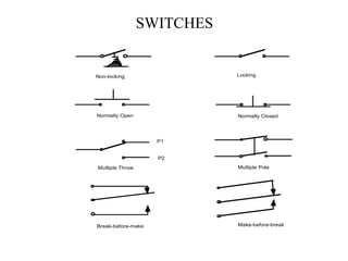
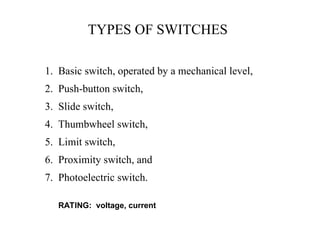
TYPES OF SWITCHES
1.Basic switch, operated by a mechanical level,
2. Push-button switch,
3. Slide switch,
4. Thumbwheel switch,
5. Limit switch,
6. Proximity switch, and
7. Photoelectric switch.
RATING: voltage, current
11.
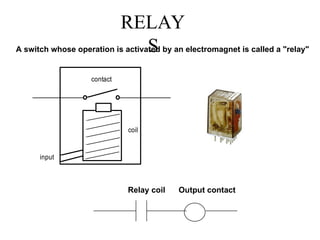
RELAY
S
A switch whoseoperation is activated by an electromagnet is called a "relay"
contact
coil
input
Relay coil Output contact
12.
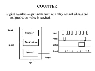
COUNTER
Digital counters outputin the form of a relay contact when a pre
assigned count value is reached.
Register
Accumulator
contact
input
reset
output
Input
Reset
Output
Count 0 1 2 3 4 5 0 1
13.
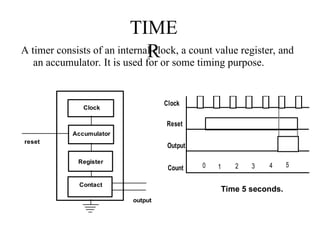
TIME
R
A timer consistsof an internal clock, a count value register, and
an accumulator. It is used for or some timing purpose.
Clock
Accumulator
contact
reset
output
Register
Contact
Time 5 seconds.
Clock
Reset
Output
Count 1 2 3 4
0 5
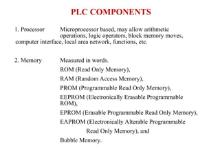
PLC COMPONENTS
1. ProcessorMicroprocessor based, may allow arithmetic
operations, logic operators, block memory moves,
computer interface, local area network, functions, etc.
2. Memory Measured in words.
ROM (Read Only Memory),
RAM (Random Access Memory),
PROM (Programmable Read Only Memory),
EEPROM (Electronically Erasable Programmable
ROM),
EPROM (Erasable Programmable Read Only Memory),
EAPROM (Electronically Alterable Programmable
Read Only Memory), and
Bubble Memory.
16.
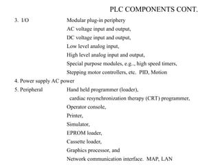
PLC COMPONENTS CONT.
3.I/O Modular plug-in periphery
AC voltage input and output,
DC voltage input and output,
Low level analog input,
High level analog input and output,
Special purpose modules, e.g.., high speed timers,
Stepping motor controllers, etc. PID, Motion
4. Power supply AC power
5. Peripheral Hand held programmer (loader),
cardiac resynchronization therapy (CRT) programmer,
Operator console,
Printer,
Simulator,
EPROM loader,
Cassette loader,
Graphics processor, and
Network communication interface. MAP, LAN
17.
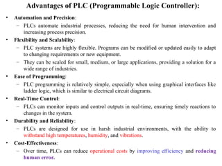
Advantages of PLC(Programmable Logic Controller):
• Automation and Precision:
– PLCs automate industrial processes, reducing the need for human intervention and
increasing process precision.
• Flexibility and Scalability:
– PLC systems are highly flexible. Programs can be modified or updated easily to adapt
to changing requirements or new equipment.
– They can be scaled for small, medium, or large applications, providing a solution for a
wide range of industries.
• Ease of Programming:
– PLC programming is relatively simple, especially when using graphical interfaces like
ladder logic, which is similar to electrical circuit diagrams.
• Real-Time Control:
– PLCs can monitor inputs and control outputs in real-time, ensuring timely reactions to
changes in the system.
• Durability and Reliability:
– PLCs are designed for use in harsh industrial environments, with the ability to
withstand high temperatures, humidity, and vibrations.
• Cost-Effectiveness:
– Over time, PLCs can reduce operational costs by improving efficiency and reducing
human error.
18.
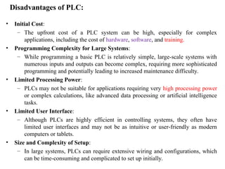
Disadvantages of PLC:
•Initial Cost:
– The upfront cost of a PLC system can be high, especially for complex
applications, including the cost of hardware, software, and training.
• Programming Complexity for Large Systems:
– While programming a basic PLC is relatively simple, large-scale systems with
numerous inputs and outputs can become complex, requiring more sophisticated
programming and potentially leading to increased maintenance difficulty.
• Limited Processing Power:
– PLCs may not be suitable for applications requiring very high processing power
or complex calculations, like advanced data processing or artificial intelligence
tasks.
• Limited User Interface:
– Although PLCs are highly efficient in controlling systems, they often have
limited user interfaces and may not be as intuitive or user-friendly as modern
computers or tablets.
• Size and Complexity of Setup:
– In large systems, PLCs can require extensive wiring and configurations, which
can be time-consuming and complicated to set up initially.
19.
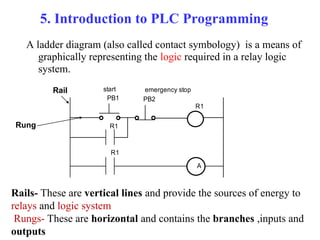
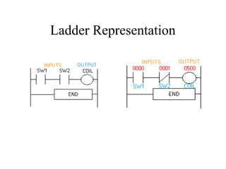
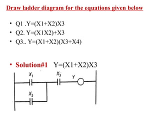
5. Introduction toPLC Programming
A ladder diagram (also called contact symbology) is a means of
graphically representing the logic required in a relay logic
system.
A
R1
PB1 PB2
R1
R1
start emergency stop
Rail
Rung
Rails- These are vertical lines and provide the sources of energy to
relays and logic system
Rungs- These are horizontal and contains the branches ,inputs and
outputs
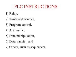
PLC INSTRUCTIONS
1) Relay,
2)Timer and counter,
3) Program control,
4) Arithmetic,
5) Data manipulation,
6) Data transfer, and
7) Others, such as sequencers.
23.
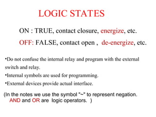
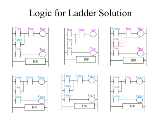
LOGIC STATES
ON :TRUE, contact closure, energize, etc.
OFF: FALSE, contact open , de-energize, etc.
(In the notes we use the symbol "~" to represent negation.
AND and OR are logic operators. )
•Do not confuse the internal relay and program with the external
switch and relay.
•Internal symbols are used for programming.
•External devices provide actual interface.
24.
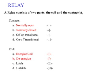
Contacts:
a. Normally open-| |-
b. Normally closed -|/|-
c. Off-on transitional -||-
d. On-off transitional -| |-
Coil:
a. Energize Coil -( )-
b. De-energize -(/)-
c. Latch -(L)-
d. Unlatch -(U)-
RELAY
A Relay consists of two parts, the coil and the contact(s).
25.
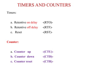
TIMERS AND COUNTERS
Timers:
a.Retentive on delay -(RTO)-
b. Retentive off delay -(RTF)-
c. Reset -(RST)-
Counter:
a. Counter up -(CTU)-
b. Counter down -(CTD)-
c. Counter reset -(CTR)-
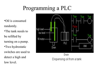
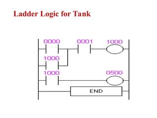
Programming a PLC
•Oilis consumed
randomly.
•The tank needs to
be refilled by
turning on a pump.
•Two hydrostatic
switches are used to
detect a high and
low level.
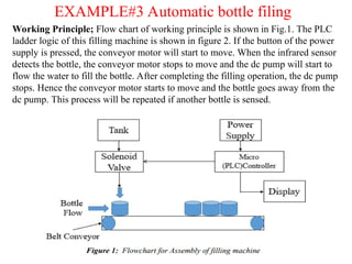
EXAMPLE#3 Automatic bottlefiling
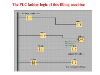
Working Principle; Flow chart of working principle is shown in Fig.1. The PLC
ladder logic of this filling machine is shown in figure 2. If the button of the power
supply is pressed, the conveyor motor will start to move. When the infrared sensor
detects the bottle, the conveyor motor stops to move and the dc pump will start to
flow the water to fill the bottle. After completing the filling operation, the dc pump
stops. Hence the conveyor motor starts to move and the bottle goes away from the
dc pump. This process will be repeated if another bottle is sensed.