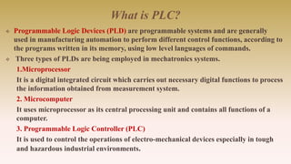
What is PLC?
Programmable Logic Devices (PLD) are programmable systems and are generally
used in manufacturing automation to perform different control functions, according to
the programs written in its memory, using low level languages of commands.
Three types of PLDs are being employed in mechatronics systems.
1.Microprocessor
It is a digital integrated circuit which carries out necessary digital functions to process
the information obtained from measurement system.
2. Microcomputer
It uses microprocessor as its central processing unit and contains all functions of a
computer.
3. Programmable Logic Controller (PLC)
It is used to control the operations of electro-mechanical devices especially in tough
and hazardous industrial environments.
3.
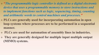
“The programmablelogic controller is defined as a digital electronic
device that uses a programmable memory to store instructions and
to implement functions such as logic, sequencing, timing, counting
and arithmetic words to control machines and processes.”
PLCs are generally used for incorporating automation in open
loop systems where processes are to be performed in a sequential
manner.
PLCs are used for automation of assembly lines in industries.
They are generally designed for multiple input multiple output
(MIMO) systems.
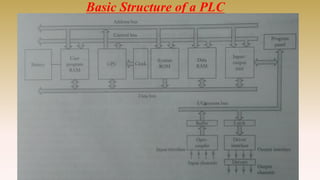
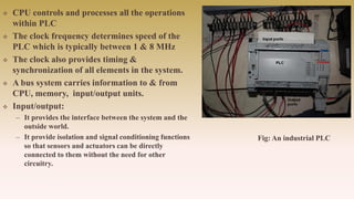
CPU controlsand processes all the operations
within PLC
The clock frequency determines speed of the
PLC which is typically between 1 & 8 MHz
The clock also provides timing &
synchronization of all elements in the system.
A bus system carries information to & from
CPU, memory, input/output units.
Input/output:
– It provides the interface between the system and the
outside world.
– It provide isolation and signal conditioning functions
so that sensors and actuators can be directly
connected to them without the need for other
circuitry.
Fig: An industrial PLC
6.
Selection of PLC
PLC’s are similar to computers but have features which are specific to their use as
controllers.
– Rugged & designed to with stand vibrations, temperature, humidity & noise.
– Interfacing for inputs & outputs is inside the controller
– Can be easily programmed.
PLC’s can be selected on:
System (task) requirements.
Application requirements.
What input/output capacity is required?
What type of inputs/outputs are required?
What size of memory is required?
What speed is required of the CPU?
Electrical requirements.
Speed of operation.
Communication requirements.
Software.
Operator interface.
Physical environments.
7.
System requirements
*what is to be achieved?
* Breaking down the task into a number of simple understandable elements, each of which can be easily described.
Application requirements
* Input and output device requirements.
* List the function required and identify a specific type of device.
* The need for special operations in addition to discrete (On/Off) logic.
* List the advanced functions required beside simple discrete logic.
Electrical Requirements
The electrical requirements for inputs, outputs, and system power;
– Incoming power (power for the control system);
– Input device voltage; and
– Output voltage and current.
Speed of Operation
How fast the control system must operate (speed of operation)
– How fast does the process occur or machine operate?
– Are there “time critical” operations or events that must be detected?
– In what time frame must the fastest action occur (input device detection to output device activation)?
– Does the control system need to count pulses from an encoder or flow-meter and respond quickly?
Communication
If the application requires sharing data outside the process, i.e. communication. such as a computer or a monitor in an operator’s
station. Communication can take place locally through a twisted-pair wire, or remotely via telephone or radio modem.
Operator Interface
In order to convey information about machine or process status, or to allow an operator to input data, many applications require
operator interfaces. Traditional operator interfaces include pushbuttons, pilot lights and LED numeric display. Electronic operator
interface devices display messages about machine status in descriptive text, display part count and track alarms. Also, they can be
used for data input.
Physical Environment
The physical environment in which the control system will be located
8.
Input / OutputProcessing
A PLC is continuously running through its program & updating it as a result
of the input signals.
There are two methods that can be used for input/output processing
1. Continuous updating
It involves the CPU scanning the input channels as they occur in the program
instructions.
Each input point is examined individually and its effect on the program determined.
There will be a built in delay about 3 ms which enables the microprocessor to avoid
counting an input signal twice.
2. Mass input/output copying
Because of an inbuilt delay in continuous updating , the time taken to examine
several hundred i/o points can become comparatively long.
In mass i/o copying , a specific area of the RAM is used as a buffer store between the
control logic and the input/output unit.
Each i/o has an address in this memory.
As the program is executed, the stored i/p data is read as required from RAM and
the logic operations are carried out.
9.
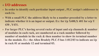
I/O addresses
In order to identify each particular input output , PLC assign’s addresses to
each i/o.
With a small PLC the address likely to be a number preceded by a letter to
indicate whether it is an input or output. Ex: for i/p X400,X 401 for o/p Y
430 , Y431.
For larger PLC’s having several racks of input and o/p channels & number
of modules in each rack, are numbered as a rack number followed by
number of module in the rack & then number to show its terminal number
in the module. Ex : the Allen Bradely PLC-5 has 1:012/03 to indicate an i/p
in rack 01 at module 12 and terminal 03.
10.
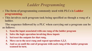
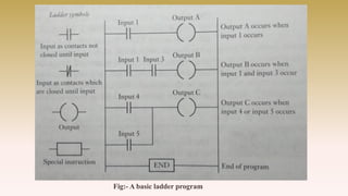
Ladder Programming
Theform of programming commonly used with PLCs is Ladder
programming.
This involves each program task being specified as though a rung of a
ladder.
The sequence followed by a PLC when carrying out a program can be
as follows:
1. Scan the input associated with one rung of the ladder program
2. Solve the logic operation involving these inputs
3. Set/reset the outputs for that rung.
4. Move on to the next rung and repeat operations 1,2,3.
5. And so on until the end of program with each rung of the ladder program
scanned in turn.
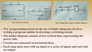
PLC programmingbased on the use of ladder diagrams involves
writing a program similar to drawing a switching circuit
The ladder diagram consists of two vertical lines representing the
power rails.
Circuits are connected as horizontal lines.
Each rung must start with an input or a series of inputs and end with
an output.
Fig: An electric circuit Fig: Comparable rung in a ladder diagram
13.
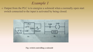
Example 1
Outputfrom the PLC is to energize a solenoid when a normally open start
switch connected to the input is activated by being closed.
Fig: switch controlling a solenoid
14.
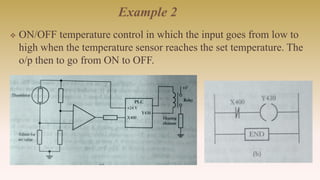
Example 2
ON/OFFtemperature control in which the input goes from low to
high when the temperature sensor reaches the set temperature. The
o/p then to go from ON to OFF.
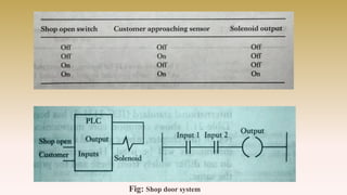
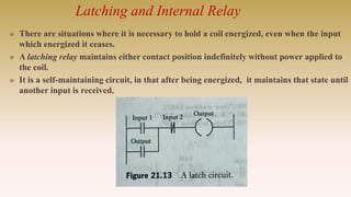
Latching and InternalRelay
There are situations where it is necessary to hold a coil energized, even when the input
which energized it ceases.
A latching relay maintains either contact position indefinitely without power applied to
the coil.
It is a self-maintaining circuit, in that after being energized, it maintains that state until
another input is received.
19.
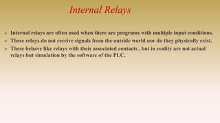
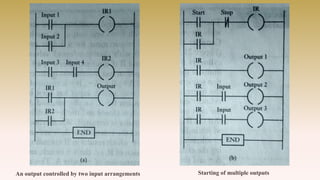
Internal Relays
Internalrelays are often used when there are programs with multiple input conditions.
These relays do not receive signals from the outside world nor do they physically exist.
These behave like relays with their associated contacts , but in reality are not actual
relays but simulation by the software of the PLC.
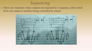
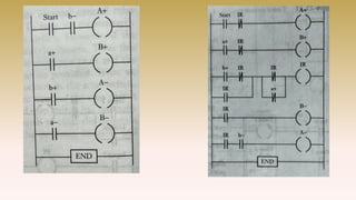
Sequencing
There aresituations where outputs are required in a sequence, with switch
from one output to another being controlled by sensor
23.
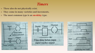
Timers
These alsodo not physically exist.
They come in many varieties and increments.
The most common type is an on-delay type.
24.
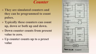
Counter
They aresimulated counters and
they can be programmed to count
pulses.
Typically these counters can count
up, down or both up and down.
Down counter counts from present
value to zero.
Up counter counts up to a preset
value
25.
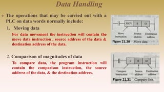
Data Handling
Theoperations that may be carried out with a
PLC on data words normally include:
1. Moving data
For data movement the instruction will contain the
move data instruction , source address of the data &
destination address of the data.
2. Comparison of magnitudes of data
To compare data, the program instruction will
contain the comparison instruction, the source
address of the data, & the destination address.
26.
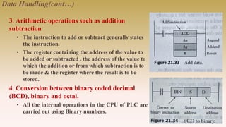
Data Handling(cont…)
3. Arithmeticoperations such as addition
subtraction
• The instruction to add or subtract generally states
the instruction.
• The register containing the address of the value to
be added or subtracted , the address of the value to
which the addition or from which subtraction is to
be made & the register where the result is to be
stored.
4. Conversion between binary coded decimal
(BCD), binary and octal.
• All the internal operations in the CPU of PLC are
carried out using Binary numbers.
27.
Summary
A programmablelogic controller is a digital electronic device that uses
programmable memory to store instructions and to implement functions such as
logic, sequencing, timing, counting and arithmetic in order to control machines
and processes and has been specifically designed to make programming easy.
The form of programming commonly used with PLC’s is ladder programming.
A latch circuit is a circuit that after being energized maintains that state until
another input is received.
The term internal relay, auxiliary relay or marker is used for what can be
considered as an internal relay in the PLC, these behaving like relays with their
associated contacts.
Timers can be considered to behave like relays with coils which when energized
result in the closure or opening of contacts after some preset time.
Counters are used to count a specified number of contact operations.
28.
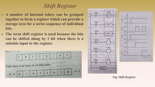
Shift Register
Anumber of internal relays can be grouped
together to form a register which can provide a
storage area for a series sequence of individual
bits.
The term shift register is used because the bits
can be shifted along by 1 bit when there is a
suitable input to the register.
Fig: Shift Register