The document provides an introduction to electro-pneumatics. It defines electro-pneumatics as the integration of electrical and pneumatic control circuits to control pneumatic components like solenoid valves. The key components of an electro-pneumatic system include input elements like switches and sensors, processing elements like relays, and final control elements such as solenoid valves. Applications examples are also provided to demonstrate how pneumatic circuits can be designed using these components along with corresponding electrical circuits. The document aims to help readers understand the basic concepts and components of electro-pneumatic systems.
![Introduction to Electro Pneumatics
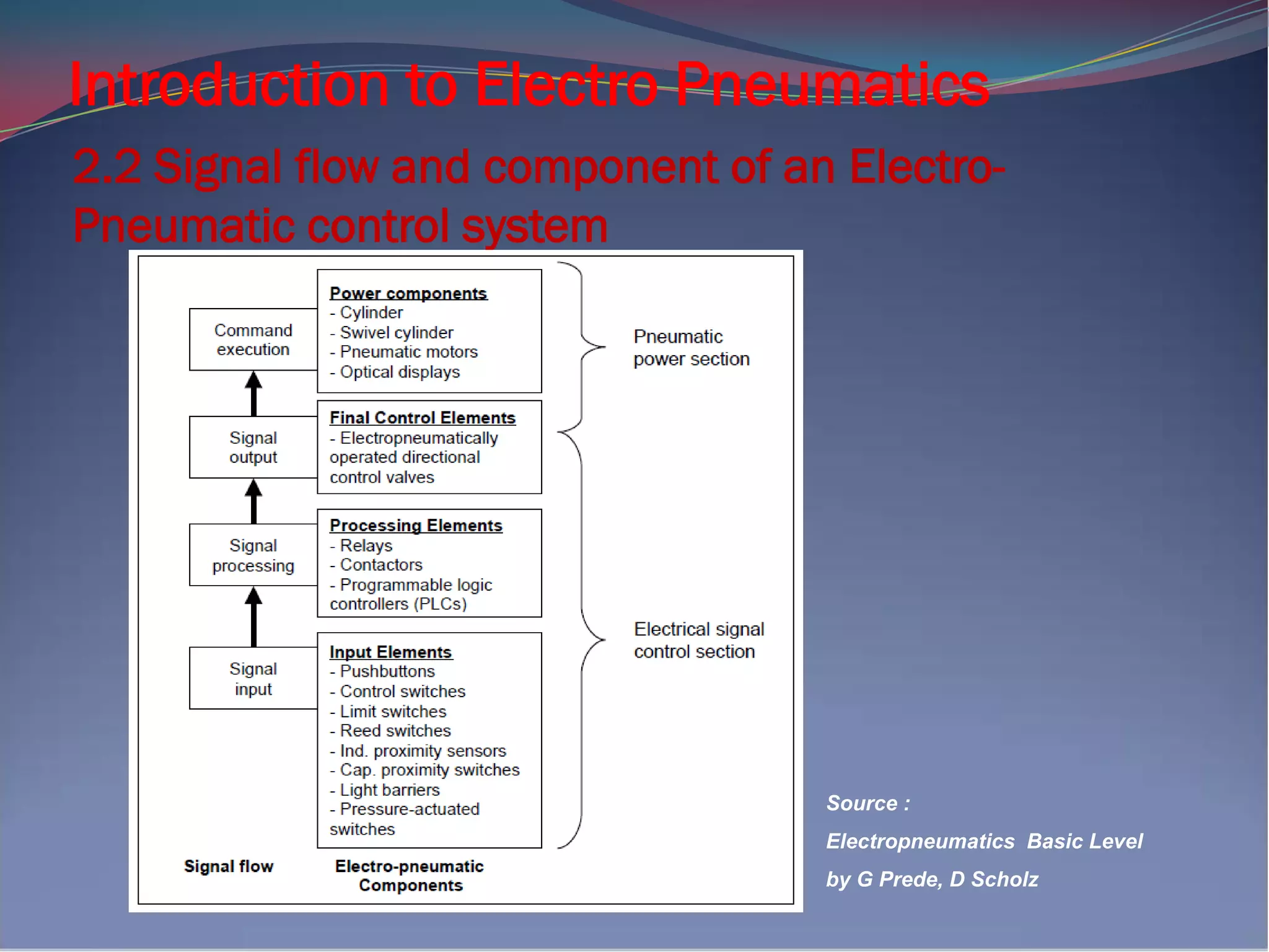
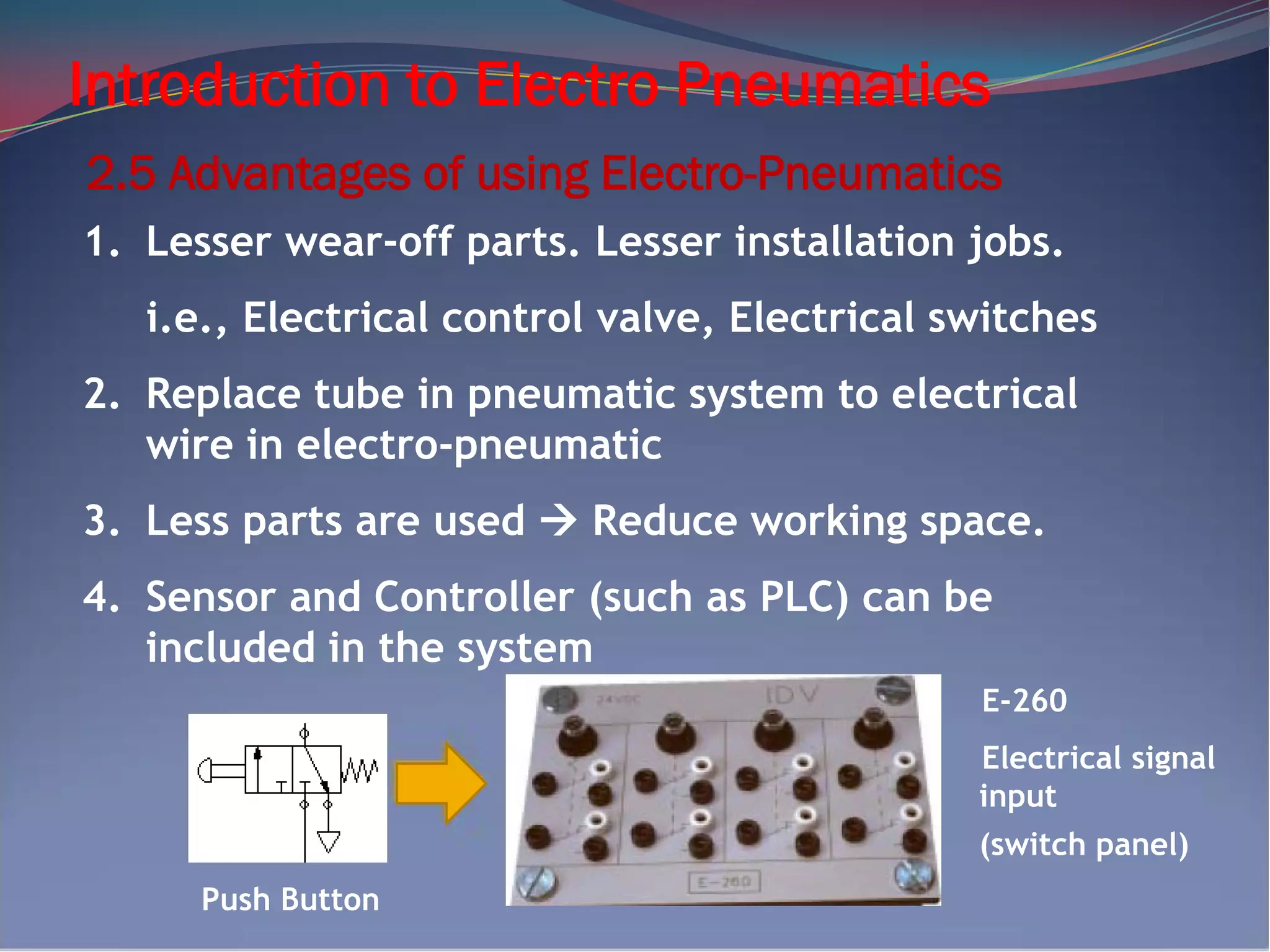
Both pneumatic & electro-pneumatic controllers have
a pneumatic power section. In an electro-pneumatics
control, the signal control section is made up of a
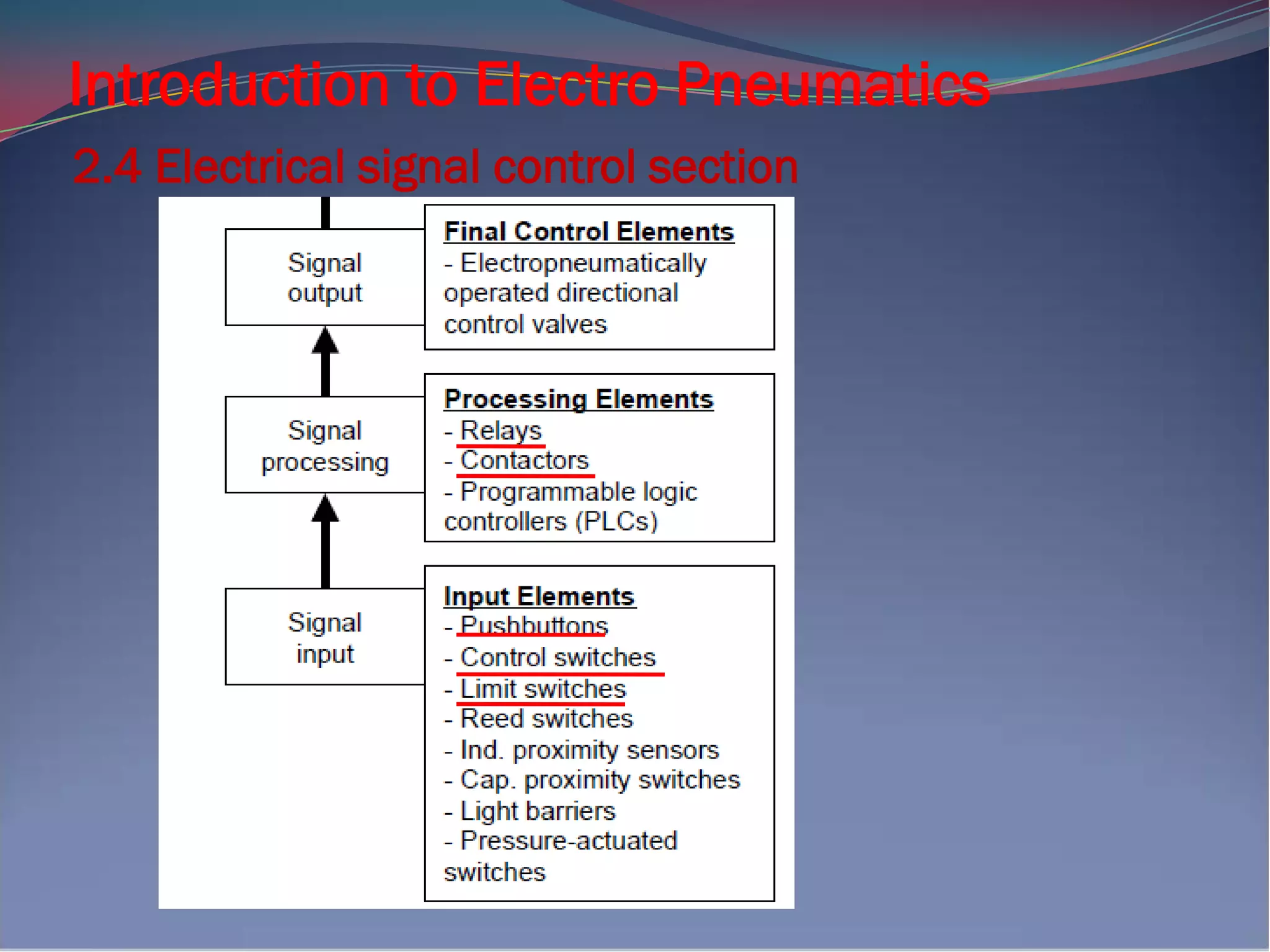
electrical components, such as electrical input
buttons, proximity switches, relays, or a
programmable logic controller (PLC).
Source : Electropneumatics – A basic, G Prede, D Scholz
Question 1 :
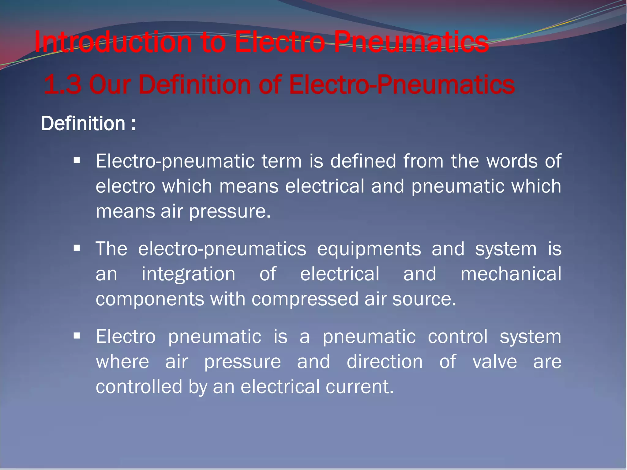
What is your definition for Electro-Pneumatics?
_____________________________________
_____________________________________
[3 marks]
1.2 Other Definition of Electro-Pneumatics](https://image.slidesharecdn.com/165000503-electro-pneumatic-210428025044/75/165000503-electro-pneumatic-3-2048.jpg)