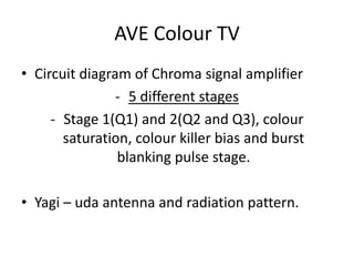
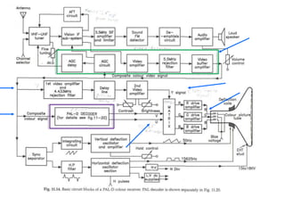
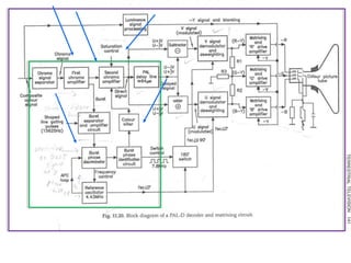
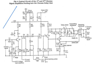
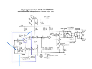
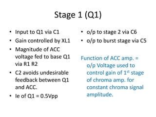
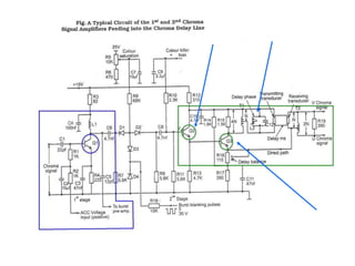
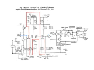
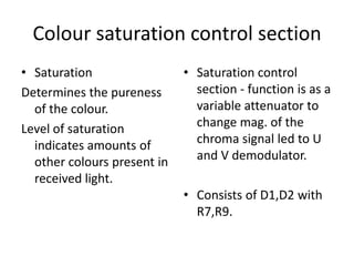
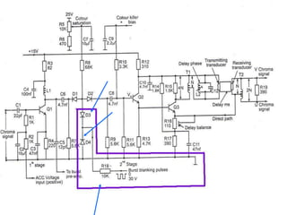
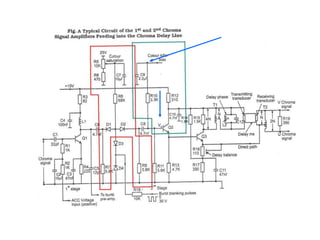
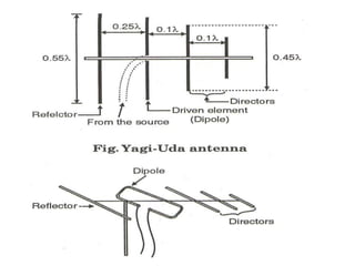
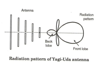
Chroma signal amplifier circuit and Yagi-uda antennaBy  Ashton
Pooja
PrathikAVE Colour TVCircuit diagram of Chroma signal amplifier
5 different stages
Stage 1(Q1) and 2(Q2 and Q3), colour saturation, colour killer bias and burst blanking pulse stage.
Yagi – uda antenna and radiation pattern.
Pal – D colour receiverVideo detector suppies composite video signal to colour decoder (pal) and y channel decoder.
o/p pal d = V and U ( scaled down colour difference signals U=0.493(B-Y) and V=0.877(R-Y)
o/p y channel = luminance (brightness)signal (y)
Given to matrix ckt for RGB colour signal generation.
Why separation of chroma signal and colour burst signal?The chroma signal separation circuit used.
Encoding= process of combining the 2 colour difference signals by translating  them to a higher freq. domain.
Since the 2 carrier freq. are suppressed in the balanced mod. of the encoder, it is necessary to regenerate them at the receiver for demod. of the chroma signal.
So,8-10 cycles of colour sub-carrier oss. o/p are transm. with sync pulses in short bursts called colour burst.
Stage 1 (Q1)Input to Q1 via C1Gain controlled by XL1Magnitude of ACC voltage fed to base Q1 via R1 R2C2 avoids undesirable feedback between Q1 and ACC.Ie of Q1 = 0.5Vppo/p to stage 2 via C6o/p to burst stage via C5Function of ACC amp. = o/p Voltage used to control gain of 1st stage of chroma amp. for constant chroma signal amplitude.
Stage 2 (Q2 and Q3)Consists of transistors Q2 and Q3Q2 acts as emitter followerQ3 acts as phase splitting amplifier i.e. to provide anti-phase chroma signal for chroma delay line circuit that separates U and V signals.
Colour saturation control sectionSaturationDetermines the pureness of the colour.Level of saturation indicates amounts of other colours present in received light.Saturation control section - function is as a variable attenuator to change mag. of the chroma signal led to U and V demodulator.Consists of D1,D2 with R7,R9.

Ave - TV receiver (PAL - D circiut main)

  • 1.
    Chroma signal amplifiercircuit and Yagi-uda antennaBy Ashton
  • 2.
  • 3.
    PrathikAVE Colour TVCircuitdiagram of Chroma signal amplifier
  • 4.
  • 5.
    Stage 1(Q1) and2(Q2 and Q3), colour saturation, colour killer bias and burst blanking pulse stage.
  • 6.
    Yagi – udaantenna and radiation pattern.
  • 7.
    Pal – Dcolour receiverVideo detector suppies composite video signal to colour decoder (pal) and y channel decoder.
  • 8.
    o/p pal d= V and U ( scaled down colour difference signals U=0.493(B-Y) and V=0.877(R-Y)
  • 9.
    o/p y channel= luminance (brightness)signal (y)
  • 10.
    Given to matrixckt for RGB colour signal generation.
  • 11.
    Why separation ofchroma signal and colour burst signal?The chroma signal separation circuit used.
  • 12.
    Encoding= process ofcombining the 2 colour difference signals by translating them to a higher freq. domain.
  • 13.
    Since the 2carrier freq. are suppressed in the balanced mod. of the encoder, it is necessary to regenerate them at the receiver for demod. of the chroma signal.
  • 14.
    So,8-10 cycles ofcolour sub-carrier oss. o/p are transm. with sync pulses in short bursts called colour burst.
  • 17.
    Stage 1 (Q1)Inputto Q1 via C1Gain controlled by XL1Magnitude of ACC voltage fed to base Q1 via R1 R2C2 avoids undesirable feedback between Q1 and ACC.Ie of Q1 = 0.5Vppo/p to stage 2 via C6o/p to burst stage via C5Function of ACC amp. = o/p Voltage used to control gain of 1st stage of chroma amp. for constant chroma signal amplitude.
  • 19.
    Stage 2 (Q2and Q3)Consists of transistors Q2 and Q3Q2 acts as emitter followerQ3 acts as phase splitting amplifier i.e. to provide anti-phase chroma signal for chroma delay line circuit that separates U and V signals.
  • 21.
    Colour saturation controlsectionSaturationDetermines the pureness of the colour.Level of saturation indicates amounts of other colours present in received light.Saturation control section - function is as a variable attenuator to change mag. of the chroma signal led to U and V demodulator.Consists of D1,D2 with R7,R9.