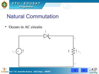
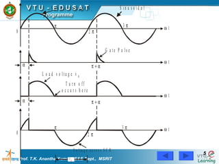
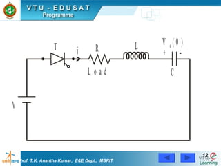
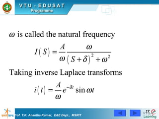
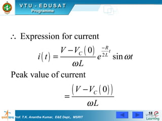
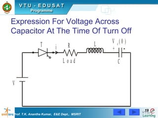
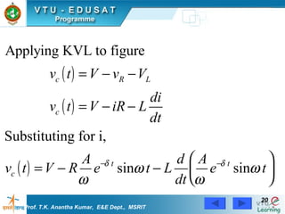
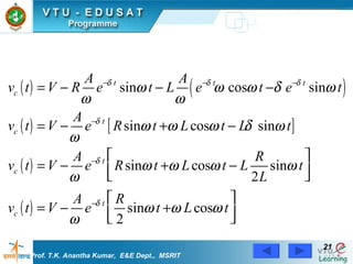
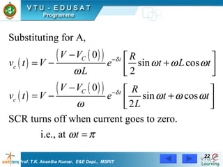
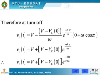
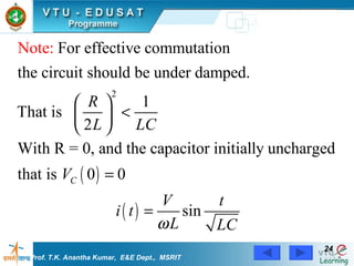
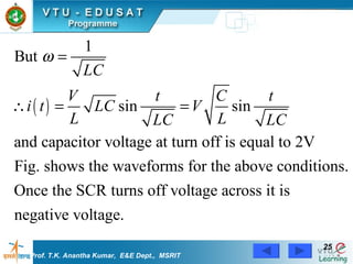
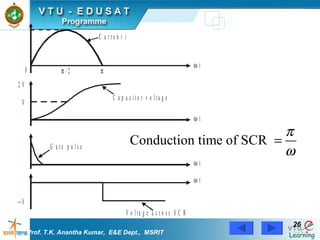
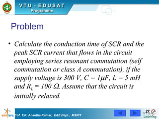
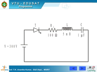
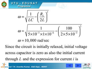
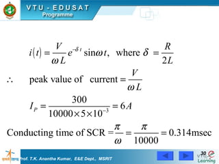
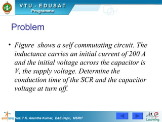
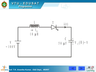
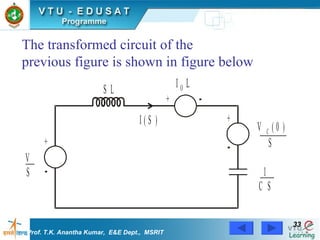
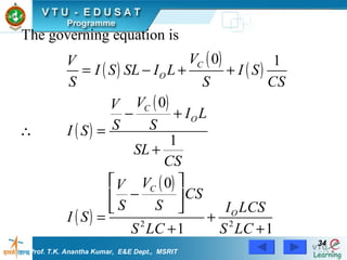
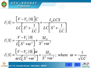
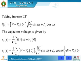
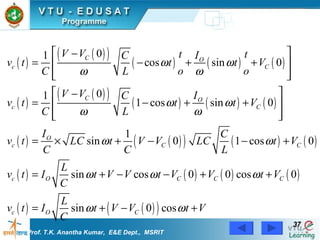
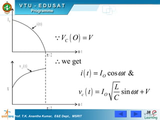
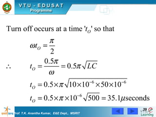
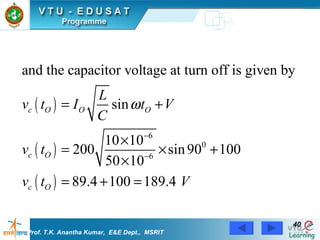
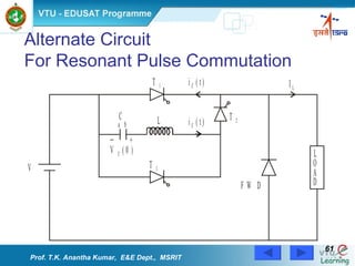
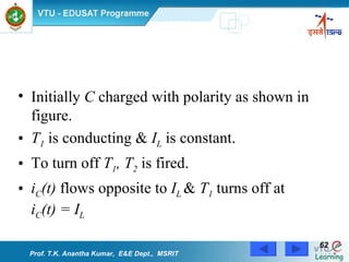
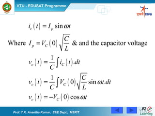
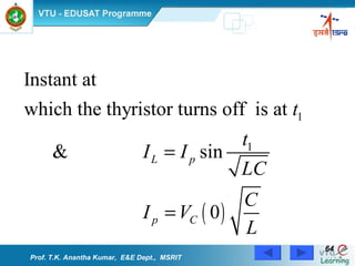
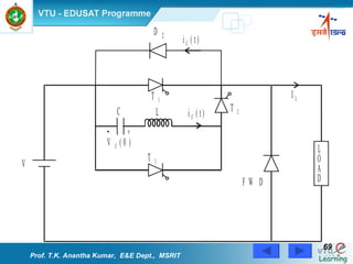
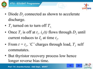
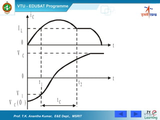
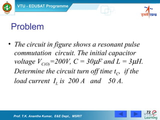
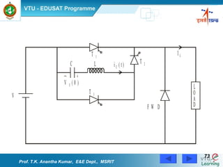
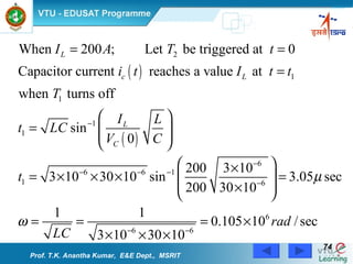
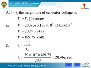
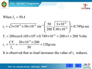
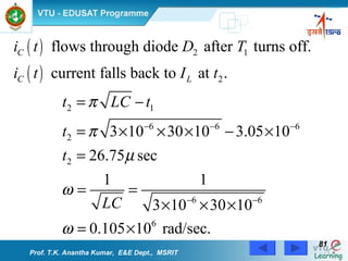
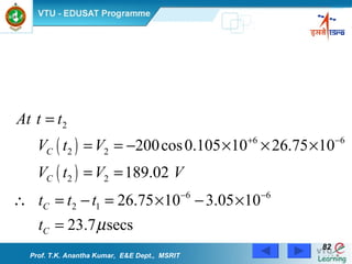
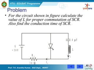
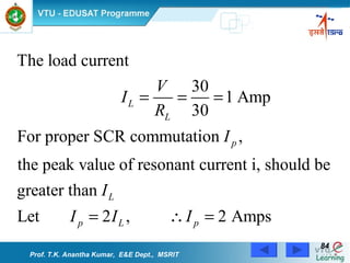
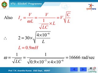
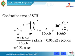
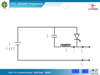
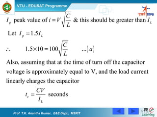
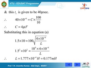
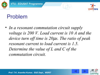
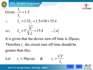
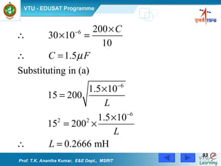
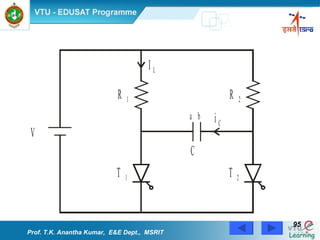
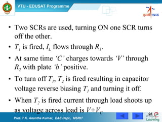
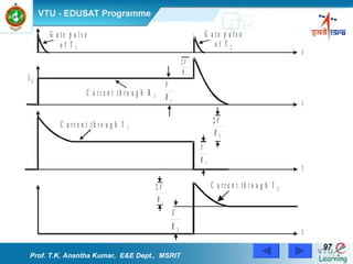
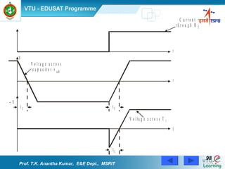
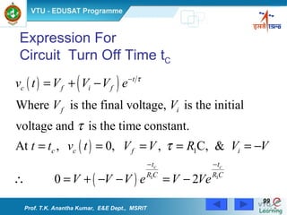
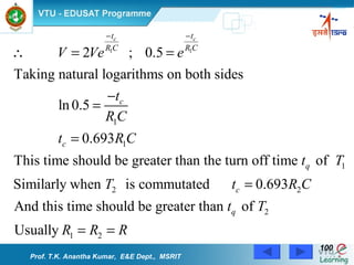
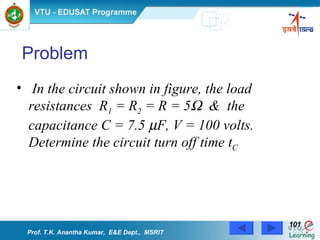
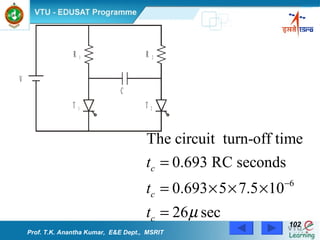
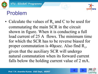
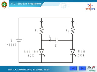
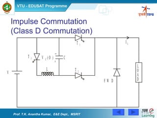
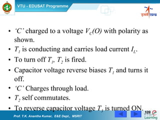
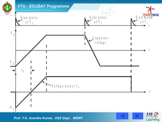
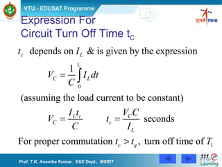
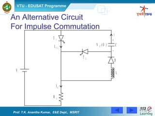
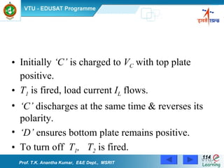
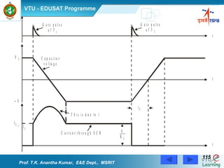
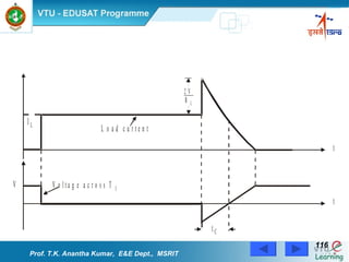
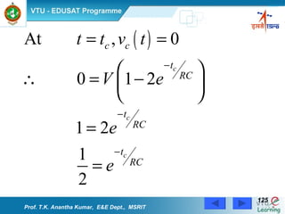
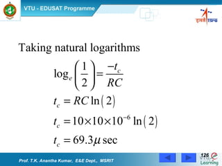
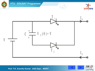
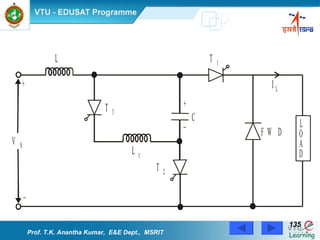
Thyristor Commutation Techniques Prof. T.K. Anantha Kumar,  E&E Dept.,  MSRIT
Introduction Commutation  Process of turning off a conducting thyristor. Current Commutation Voltage Commutation Prof. T.K. Anantha Kumar,  E&E Dept.,  MSRIT
Methods of Commutation Natural Commutation Forced Commutation Prof. T.K. Anantha Kumar,  E&E Dept.,  MSRIT
Natural Commutation Occurs in AC circuits Prof. T.K. Anantha Kumar,  E&E Dept.,  MSRIT
Prof. T.K. Anantha Kumar,  E&E Dept.,  MSRIT
Natural Commutation of Thyristors takes place in  AC voltage controllers. Phase controlled rectifiers. Cyclo converters. Prof. T.K. Anantha Kumar,  E&E Dept.,  MSRIT
Forced Commutation Applied to dc circuits Commutation achieved by reverse biasing the SCR or by reducing the SCR current below holding current value. Commutating elements such as inductance and capacitance are used for commutation purpose. Prof. T.K. Anantha Kumar,  E&E Dept.,  MSRIT
Methods of Forced Commutation Self commutation. Resonant pulse commutation. Complementary commutation. Impulse commutation. External pulse commutation. Load Commutation. Line Commutation. Prof. T.K. Anantha Kumar,  E&E Dept.,  MSRIT
Forced Commutation is applied to Choppers. Inverters. Prof. T.K. Anantha Kumar,  E&E Dept.,  MSRIT
Self Commutation  Or  Load Commutation  Or  Class A Commutation  (Commutation By Resonating The Load) Prof. T.K. Anantha Kumar,  E&E Dept.,  MSRIT
Circuit is under damped by including suitable values of L & C in series with load. Oscillating current flows. SCR is turned off when current is zero. Prof. T.K. Anantha Kumar,  E&E Dept.,  MSRIT
Prof. T.K. Anantha Kumar,  E&E Dept.,  MSRIT
Expression for Current Fig. shows a transformed network Prof. T.K. Anantha Kumar,  E&E Dept.,  MSRIT
Prof. T.K. Anantha Kumar,  E&E Dept.,  MSRIT
Expression For Voltage Across Capacitor At The Time Of Turn Off  Prof. T.K. Anantha Kumar,  E&E Dept.,  MSRIT
Prof. T.K. Anantha Kumar,  E&E Dept.,  MSRIT
Problem Calculate the conduction time of SCR and the peak SCR current that flows in the circuit employing series resonant commutation (self commutation or class A commutation), if the supply voltage is 300 V, C = 1  F, L = 5 mH and R L  = 100   . Assume that the circuit is initially relaxed. Prof. T.K. Anantha Kumar,  E&E Dept.,  MSRIT
Prof. T.K. Anantha Kumar,  E&E Dept.,  MSRIT
Problem Figure  shows a self commutating circuit. The inductance carries an initial current of 200 A and the initial voltage across the capacitor is V, the supply voltage. Determine the conduction time of the SCR and the capacitor voltage at turn off. Prof. T.K. Anantha Kumar,  E&E Dept.,  MSRIT
Prof. T.K. Anantha Kumar,  E&E Dept.,  MSRIT
The transformed circuit of the  previous figure is shown in figure below Prof. T.K. Anantha Kumar,  E&E Dept.,  MSRIT
Prof. T.K. Anantha Kumar,  E&E Dept.,  MSRIT
In the circuit shown in figure V = 600 volts, initial capacitor voltage is zero, L = 20   H,  C=50  F and the current through the inductance at the time of SCR triggering is  I O  = 350 A. Determine  Peak values of capacitor voltage and current Conduction time of T 1 .   Problem Prof. T.K. Anantha Kumar,  E&E Dept.,  MSRIT
Prof. T.K. Anantha Kumar,  E&E Dept.,  MSRIT
To calculate conduction time of T 1 The waveform of capacitor current is shown in figure. When the capacitor current becomes zero the SCR turns off. Prof. T.K. Anantha Kumar,  E&E Dept.,  MSRIT
Prof. T.K. Anantha Kumar,  E&E Dept.,  MSRIT
Resonant Pulse Commutation  (Class B Commutation) Prof. T.K. Anantha Kumar,  E&E Dept.,  MSRIT
Series LC circuit connected across thyristor ‘T’. Initially ‘C’ is charged to ‘V’ volts with plate ‘a’ as positive. Current in LC oscillates when SCR is ON. ‘ T’  turns off when capacitor discharges through thyristor in a direction opposite to  I L Prof. T.K. Anantha Kumar,  E&E Dept.,  MSRIT
Prof. T.K. Anantha Kumar,  E&E Dept.,  MSRIT
Expression For t C  ,  the Circuit Turn Off Time  Prof. T.K. Anantha Kumar,  E&E Dept.,  MSRIT
Prof. T.K. Anantha Kumar,  E&E Dept.,  MSRIT
The LC Circuit  During The Commutation Period  LC Circuit   Transformed Circuit   Prof. T.K. Anantha Kumar,  E&E Dept.,  MSRIT
Prof. T.K. Anantha Kumar,  E&E Dept.,  MSRIT
Expression For  Conduction Time Of SCR Prof. T.K. Anantha Kumar,  E&E Dept.,  MSRIT
Alternate Circuit For Resonant Pulse Commutation Prof. T.K. Anantha Kumar,  E&E Dept.,  MSRIT
Initially  C  charged with polarity as shown in figure. T 1   is conducting &  I L   is constant. To turn off  T 1 , T 2   is fired. i C (t)  flows opposite to  I L  &  T 1  turns off at  i C (t) = I L Prof. T.K. Anantha Kumar,  E&E Dept.,  MSRIT
Prof. T.K. Anantha Kumar,  E&E Dept.,  MSRIT
Expression For t C Prof. T.K. Anantha Kumar,  E&E Dept.,  MSRIT
Prof. T.K. Anantha Kumar,  E&E Dept.,  MSRIT
Resonant Pulse Commutation With Accelerating Diode  Prof. T.K. Anantha Kumar,  E&E Dept.,  MSRIT
Prof. T.K. Anantha Kumar,  E&E Dept.,  MSRIT
Diode  D 2  connected as shown to accelerate discharge. T 2  turned on to turn off  T 1 . Once  T 1  is off at  t 1 .  i C (t)  flows through  D 2  until current reduces to  I L  at time  t 2 . From  t = t 2  ,   ‘C’  charges through load,  T 2   self commutates. But thyristor recovery process low hence longer reverse bias time. Prof. T.K. Anantha Kumar,  E&E Dept.,  MSRIT
Prof. T.K. Anantha Kumar,  E&E Dept.,  MSRIT
Problem The circuit in figure shows a resonant pulse commutation  circuit. The initial capacitor voltage V C(O) =200V, C = 30  F and L = 3  H. Determine the circuit turn off time t C ,  if the load current  I L  is  200 A  and  50 A. Prof. T.K. Anantha Kumar,  E&E Dept.,  MSRIT
Prof. T.K. Anantha Kumar,  E&E Dept.,  MSRIT
Problem Prof. T.K. Anantha Kumar,  E&E Dept.,  MSRIT
Prof. T.K. Anantha Kumar,  E&E Dept.,  MSRIT
Problem For the circuit shown in figure calculate the value of L for proper commutation of SCR. Also find the conduction time of SCR . Prof. T.K. Anantha Kumar,  E&E Dept.,  MSRIT
Prof. T.K. Anantha Kumar,  E&E Dept.,  MSRIT
Problem For the circuit shown in figure given that the load current to be commutated is 10 A, turn off time required is 40  sec and the supply voltage is 100 V. Obtain the proper values of commutating elements. Prof. T.K. Anantha Kumar,  E&E Dept.,  MSRIT
Prof. T.K. Anantha Kumar,  E&E Dept.,  MSRIT
Problem In a resonant commutation circuit supply voltage is 200 V. Load current is 10 A and the device turn off time is 20  s. The ratio of peak resonant current to load current is 1.5. Determine the value of L and C of the commutation circuit.   Prof. T.K. Anantha Kumar,  E&E Dept.,  MSRIT
Prof. T.K. Anantha Kumar,  E&E Dept.,  MSRIT
Complementary Commutation (Class C Commutation, Parallel Capacitor Commutation) Prof. T.K. Anantha Kumar,  E&E Dept.,  MSRIT
Prof. T.K. Anantha Kumar,  E&E Dept.,  MSRIT
Two SCRs are used, turning ON one SCR turns off the other. T 1  is fired,  I L  flows through  R 1 . At same time  ‘C’  charges towards  ‘V’  through  R 2  with plate  ‘b’  positive. To turn off  T 1 ,  T 2  is fired resulting in capacitor voltage reverse biasing  T 1  and turning it off. When  T 2  is fired current through load shoots up as voltage across load is  V+V C Prof. T.K. Anantha Kumar,  E&E Dept.,  MSRIT
Prof. T.K. Anantha Kumar,  E&E Dept.,  MSRIT
Expression For  Circuit  Turn Off Time t C Prof. T.K. Anantha Kumar,  E&E Dept.,  MSRIT
Prof. T.K. Anantha Kumar,  E&E Dept.,  MSRIT
In the circuit shown in figure, the load resistances  R 1  = R 2  = R = 5    &  the capacitance C = 7.5   F, V = 100 volts.  Determine the circuit turn off time t C   Problem Prof. T.K. Anantha Kumar,  E&E Dept.,  MSRIT
Prof. T.K. Anantha Kumar,  E&E Dept.,  MSRIT
Calculate the values of R L  and C to be used for commutating the main SCR in the circuit shown in figure. When it is conducting a full load current of 25 A  flows. The minimum time for which the SCR has to be reverse biased for proper commutation is 40  sec. Also find R 1 , given that the auxiliary SCR will undergo natural commutation when its forward current falls below the holding current value of 2 mA.  Problem Prof. T.K. Anantha Kumar,  E&E Dept.,  MSRIT
Prof. T.K. Anantha Kumar,  E&E Dept.,  MSRIT
In this circuit only the main SCR carries the load and the auxiliary SCR is used to turn off the main SCR. Once the main SCR turns off the current through the auxiliary SCR is the sum of the capacitor charging current  i C  and the current  i 1   through  R 1 ,  i C  reduces to zero after a time  t C  and hence the auxiliary SCR turns off automatically after a time  t C ,  i 1   should be less than the holding current. Prof. T.K. Anantha Kumar,  E&E Dept.,  MSRIT
Prof. T.K. Anantha Kumar,  E&E Dept.,  MSRIT
Impulse Commutation (Class D Commutation) Prof. T.K. Anantha Kumar,  E&E Dept.,  MSRIT
‘ C’  charged to a voltage  V C (O)  with polarity as shown. T 1  is conducting and carries load current  I L . To turn off  T 1 , T 2  is fired. Capacitor voltage reverse biases  T 1  and turns it off. ‘ C’  Charges through load. T 2  self commutates. To reverse capacitor voltage  T 3  is turned ON. Prof. T.K. Anantha Kumar,  E&E Dept.,  MSRIT
Prof. T.K. Anantha Kumar,  E&E Dept.,  MSRIT
Expression For  Circuit Turn Off Time t C Prof. T.K. Anantha Kumar,  E&E Dept.,  MSRIT
T 1  is turned off by applying a negative voltage across its terminals. Hence this is voltage commutation. t C  depends on load current. For higher load currents t C  is small. This is a disadvantage of this circuit. When T 2  is fired, voltage across the load is V+V C ; hence the current through load shoots up and then decays as the capacitor starts charging. Prof. T.K. Anantha Kumar,  E&E Dept.,  MSRIT
An Alternative Circuit  For Impulse Commutation  Prof. T.K. Anantha Kumar,  E&E Dept.,  MSRIT
Initially  ‘C’  is charged to  V C  with top plate positive. T 1  is fired, load current  I L  flows. ‘ C’  discharges at the same time & reverses its polarity. ‘ D’  ensures bottom plate remains positive. To turn off  T 1 ,  T 2  is fired. Prof. T.K. Anantha Kumar,  E&E Dept.,  MSRIT
Prof. T.K. Anantha Kumar,  E&E Dept.,  MSRIT
Problem An impulse commutated thyristor circuit is shown in figure.  Determine the available turn off time of the circuit if  V = 100 V, R = 10    and C = 10   F.  Voltage across capacitor before  T 2   is fired is V volts with polarity as shown.   Prof. T.K. Anantha Kumar,  E&E Dept.,  MSRIT
Prof. T.K. Anantha Kumar,  E&E Dept.,  MSRIT
When T 2  is triggered  the circuit is as shown in figure  Prof. T.K. Anantha Kumar,  E&E Dept.,  MSRIT
Writing the transform circuit, we obtain Prof. T.K. Anantha Kumar,  E&E Dept.,  MSRIT
Prof. T.K. Anantha Kumar,  E&E Dept.,  MSRIT
The waveform of  v C (t)   is shown in figure  Prof. T.K. Anantha Kumar,  E&E Dept.,  MSRIT
Prof. T.K. Anantha Kumar,  E&E Dept.,  MSRIT
Problem In the commutation circuit shown in figure  C = 20   F, the input voltage V varies between 180 and 220 V and the load current varies between 50 and 200 A. Determine the minimum and maximum values of available turn off time t C . Prof. T.K. Anantha Kumar,  E&E Dept.,  MSRIT
Prof. T.K. Anantha Kumar,  E&E Dept.,  MSRIT
External Pulse  Commutation (Class E Commutation)  Prof. T.K. Anantha Kumar,  E&E Dept.,  MSRIT
T 1  is conducting &  R L  is connected across supply. T 3  is fired &  ‘C’  is charged to  2V AUX  with upper plate positive. T 3  is self commutated. To turn off  T 1 ,  T 2  is fired. T 2  ON results in a reverse voltage  V S  – 2V AUX   appearing   across  T 1. Prof. T.K. Anantha Kumar,  E&E Dept.,  MSRIT
Load Side Commutation In load side commutation the discharging and recharging of capacitor takes place through the load. Hence to test the commutation circuit the load has to be connected. Examples of load side commutation are Resonant Pulse Commutation and Impulse Commutation.  Prof. T.K. Anantha Kumar,  E&E Dept.,  MSRIT
Line Side Commutation In this type of commutation the discharging and recharging of capacitor takes place through the supply.  Prof. T.K. Anantha Kumar,  E&E Dept.,  MSRIT
Prof. T.K. Anantha Kumar,  E&E Dept.,  MSRIT
Thyristor T 2  is fired to charge the capacitor ‘C’. When ‘C’ charges to a voltage of 2V,  T 2  is self commutated. To reverse the voltage of capacitor to -2V, thyristor T 3  is fired and T 3  commutates by itself. Assuming that T 1  is conducting and carries a load current I L  thyristor T 2  is fired to turn off T 1 .  Prof. T.K. Anantha Kumar,  E&E Dept.,  MSRIT
The turning ON of T 2  will result in forward biasing the diode (FWD) and applying a reverse voltage of 2V acrossT 1 . This turns off T 1 , thus the discharging and recharging of capacitor is done through the supply and the commutation circuit can be tested without load.  Prof. T.K. Anantha Kumar,  E&E Dept.,  MSRIT

Thyristor Commutation Techniques

  • 1.
    Thyristor Commutation TechniquesProf. T.K. Anantha Kumar, E&E Dept., MSRIT
  • 2.
    Introduction Commutation Process of turning off a conducting thyristor. Current Commutation Voltage Commutation Prof. T.K. Anantha Kumar, E&E Dept., MSRIT
  • 3.
    Methods of CommutationNatural Commutation Forced Commutation Prof. T.K. Anantha Kumar, E&E Dept., MSRIT
  • 4.
    Natural Commutation Occursin AC circuits Prof. T.K. Anantha Kumar, E&E Dept., MSRIT
  • 5.
    Prof. T.K. AnanthaKumar, E&E Dept., MSRIT
  • 6.
    Natural Commutation ofThyristors takes place in AC voltage controllers. Phase controlled rectifiers. Cyclo converters. Prof. T.K. Anantha Kumar, E&E Dept., MSRIT
  • 7.
    Forced Commutation Appliedto dc circuits Commutation achieved by reverse biasing the SCR or by reducing the SCR current below holding current value. Commutating elements such as inductance and capacitance are used for commutation purpose. Prof. T.K. Anantha Kumar, E&E Dept., MSRIT
  • 8.
    Methods of ForcedCommutation Self commutation. Resonant pulse commutation. Complementary commutation. Impulse commutation. External pulse commutation. Load Commutation. Line Commutation. Prof. T.K. Anantha Kumar, E&E Dept., MSRIT
  • 9.
    Forced Commutation isapplied to Choppers. Inverters. Prof. T.K. Anantha Kumar, E&E Dept., MSRIT
  • 10.
    Self Commutation Or Load Commutation Or Class A Commutation (Commutation By Resonating The Load) Prof. T.K. Anantha Kumar, E&E Dept., MSRIT
  • 11.
    Circuit is underdamped by including suitable values of L & C in series with load. Oscillating current flows. SCR is turned off when current is zero. Prof. T.K. Anantha Kumar, E&E Dept., MSRIT
  • 12.
    Prof. T.K. AnanthaKumar, E&E Dept., MSRIT
  • 13.
    Expression for CurrentFig. shows a transformed network Prof. T.K. Anantha Kumar, E&E Dept., MSRIT
  • 14.
    Prof. T.K. AnanthaKumar, E&E Dept., MSRIT
  • 15.
    Prof. T.K. AnanthaKumar, E&E Dept., MSRIT
  • 16.
    Prof. T.K. AnanthaKumar, E&E Dept., MSRIT
  • 17.
    Prof. T.K. AnanthaKumar, E&E Dept., MSRIT
  • 18.
    Prof. T.K. AnanthaKumar, E&E Dept., MSRIT
  • 19.
    Expression For VoltageAcross Capacitor At The Time Of Turn Off Prof. T.K. Anantha Kumar, E&E Dept., MSRIT
  • 20.
    Prof. T.K. AnanthaKumar, E&E Dept., MSRIT
  • 21.
    Prof. T.K. AnanthaKumar, E&E Dept., MSRIT
  • 22.
    Prof. T.K. AnanthaKumar, E&E Dept., MSRIT
  • 23.
    Prof. T.K. AnanthaKumar, E&E Dept., MSRIT
  • 24.
    Prof. T.K. AnanthaKumar, E&E Dept., MSRIT
  • 25.
    Prof. T.K. AnanthaKumar, E&E Dept., MSRIT
  • 26.
    Prof. T.K. AnanthaKumar, E&E Dept., MSRIT
  • 27.
    Problem Calculate theconduction time of SCR and the peak SCR current that flows in the circuit employing series resonant commutation (self commutation or class A commutation), if the supply voltage is 300 V, C = 1  F, L = 5 mH and R L = 100  . Assume that the circuit is initially relaxed. Prof. T.K. Anantha Kumar, E&E Dept., MSRIT
  • 28.
    Prof. T.K. AnanthaKumar, E&E Dept., MSRIT
  • 29.
    Prof. T.K. AnanthaKumar, E&E Dept., MSRIT
  • 30.
    Prof. T.K. AnanthaKumar, E&E Dept., MSRIT
  • 31.
    Problem Figure shows a self commutating circuit. The inductance carries an initial current of 200 A and the initial voltage across the capacitor is V, the supply voltage. Determine the conduction time of the SCR and the capacitor voltage at turn off. Prof. T.K. Anantha Kumar, E&E Dept., MSRIT
  • 32.
    Prof. T.K. AnanthaKumar, E&E Dept., MSRIT
  • 33.
    The transformed circuitof the previous figure is shown in figure below Prof. T.K. Anantha Kumar, E&E Dept., MSRIT
  • 34.
    Prof. T.K. AnanthaKumar, E&E Dept., MSRIT
  • 35.
    Prof. T.K. AnanthaKumar, E&E Dept., MSRIT
  • 36.
    Prof. T.K. AnanthaKumar, E&E Dept., MSRIT
  • 37.
    Prof. T.K. AnanthaKumar, E&E Dept., MSRIT
  • 38.
    Prof. T.K. AnanthaKumar, E&E Dept., MSRIT
  • 39.
    Prof. T.K. AnanthaKumar, E&E Dept., MSRIT
  • 40.
    Prof. T.K. AnanthaKumar, E&E Dept., MSRIT
  • 41.
    In the circuitshown in figure V = 600 volts, initial capacitor voltage is zero, L = 20  H, C=50  F and the current through the inductance at the time of SCR triggering is I O = 350 A. Determine Peak values of capacitor voltage and current Conduction time of T 1 . Problem Prof. T.K. Anantha Kumar, E&E Dept., MSRIT
  • 42.
    Prof. T.K. AnanthaKumar, E&E Dept., MSRIT
  • 43.
    Prof. T.K. AnanthaKumar, E&E Dept., MSRIT
  • 44.
    Prof. T.K. AnanthaKumar, E&E Dept., MSRIT
  • 45.
    Prof. T.K. AnanthaKumar, E&E Dept., MSRIT
  • 46.
    Prof. T.K. AnanthaKumar, E&E Dept., MSRIT
  • 47.
    To calculate conductiontime of T 1 The waveform of capacitor current is shown in figure. When the capacitor current becomes zero the SCR turns off. Prof. T.K. Anantha Kumar, E&E Dept., MSRIT
  • 48.
    Prof. T.K. AnanthaKumar, E&E Dept., MSRIT
  • 49.
    Prof. T.K. AnanthaKumar, E&E Dept., MSRIT
  • 50.
    Resonant Pulse Commutation (Class B Commutation) Prof. T.K. Anantha Kumar, E&E Dept., MSRIT
  • 51.
    Series LC circuitconnected across thyristor ‘T’. Initially ‘C’ is charged to ‘V’ volts with plate ‘a’ as positive. Current in LC oscillates when SCR is ON. ‘ T’ turns off when capacitor discharges through thyristor in a direction opposite to I L Prof. T.K. Anantha Kumar, E&E Dept., MSRIT
  • 52.
    Prof. T.K. AnanthaKumar, E&E Dept., MSRIT
  • 53.
    Prof. T.K. AnanthaKumar, E&E Dept., MSRIT
  • 54.
    Expression For tC , the Circuit Turn Off Time Prof. T.K. Anantha Kumar, E&E Dept., MSRIT
  • 55.
    Prof. T.K. AnanthaKumar, E&E Dept., MSRIT
  • 56.
    The LC Circuit During The Commutation Period LC Circuit Transformed Circuit Prof. T.K. Anantha Kumar, E&E Dept., MSRIT
  • 57.
    Prof. T.K. AnanthaKumar, E&E Dept., MSRIT
  • 58.
    Prof. T.K. AnanthaKumar, E&E Dept., MSRIT
  • 59.
    Prof. T.K. AnanthaKumar, E&E Dept., MSRIT
  • 60.
    Expression For Conduction Time Of SCR Prof. T.K. Anantha Kumar, E&E Dept., MSRIT
  • 61.
    Alternate Circuit ForResonant Pulse Commutation Prof. T.K. Anantha Kumar, E&E Dept., MSRIT
  • 62.
    Initially C charged with polarity as shown in figure. T 1 is conducting & I L is constant. To turn off T 1 , T 2 is fired. i C (t) flows opposite to I L & T 1 turns off at i C (t) = I L Prof. T.K. Anantha Kumar, E&E Dept., MSRIT
  • 63.
    Prof. T.K. AnanthaKumar, E&E Dept., MSRIT
  • 64.
    Prof. T.K. AnanthaKumar, E&E Dept., MSRIT
  • 65.
    Prof. T.K. AnanthaKumar, E&E Dept., MSRIT
  • 66.
    Expression For tC Prof. T.K. Anantha Kumar, E&E Dept., MSRIT
  • 67.
    Prof. T.K. AnanthaKumar, E&E Dept., MSRIT
  • 68.
    Resonant Pulse CommutationWith Accelerating Diode Prof. T.K. Anantha Kumar, E&E Dept., MSRIT
  • 69.
    Prof. T.K. AnanthaKumar, E&E Dept., MSRIT
  • 70.
    Diode D2 connected as shown to accelerate discharge. T 2 turned on to turn off T 1 . Once T 1 is off at t 1 . i C (t) flows through D 2 until current reduces to I L at time t 2 . From t = t 2 , ‘C’ charges through load, T 2 self commutates. But thyristor recovery process low hence longer reverse bias time. Prof. T.K. Anantha Kumar, E&E Dept., MSRIT
  • 71.
    Prof. T.K. AnanthaKumar, E&E Dept., MSRIT
  • 72.
    Problem The circuitin figure shows a resonant pulse commutation circuit. The initial capacitor voltage V C(O) =200V, C = 30  F and L = 3  H. Determine the circuit turn off time t C , if the load current I L is 200 A and 50 A. Prof. T.K. Anantha Kumar, E&E Dept., MSRIT
  • 73.
    Prof. T.K. AnanthaKumar, E&E Dept., MSRIT
  • 74.
    Prof. T.K. AnanthaKumar, E&E Dept., MSRIT
  • 75.
    Prof. T.K. AnanthaKumar, E&E Dept., MSRIT
  • 76.
    Prof. T.K. AnanthaKumar, E&E Dept., MSRIT
  • 77.
    Problem Prof. T.K.Anantha Kumar, E&E Dept., MSRIT
  • 78.
    Prof. T.K. AnanthaKumar, E&E Dept., MSRIT
  • 79.
    Prof. T.K. AnanthaKumar, E&E Dept., MSRIT
  • 80.
    Prof. T.K. AnanthaKumar, E&E Dept., MSRIT
  • 81.
    Prof. T.K. AnanthaKumar, E&E Dept., MSRIT
  • 82.
    Prof. T.K. AnanthaKumar, E&E Dept., MSRIT
  • 83.
    Problem For thecircuit shown in figure calculate the value of L for proper commutation of SCR. Also find the conduction time of SCR . Prof. T.K. Anantha Kumar, E&E Dept., MSRIT
  • 84.
    Prof. T.K. AnanthaKumar, E&E Dept., MSRIT
  • 85.
    Prof. T.K. AnanthaKumar, E&E Dept., MSRIT
  • 86.
    Prof. T.K. AnanthaKumar, E&E Dept., MSRIT
  • 87.
    Problem For thecircuit shown in figure given that the load current to be commutated is 10 A, turn off time required is 40  sec and the supply voltage is 100 V. Obtain the proper values of commutating elements. Prof. T.K. Anantha Kumar, E&E Dept., MSRIT
  • 88.
    Prof. T.K. AnanthaKumar, E&E Dept., MSRIT
  • 89.
    Prof. T.K. AnanthaKumar, E&E Dept., MSRIT
  • 90.
    Prof. T.K. AnanthaKumar, E&E Dept., MSRIT
  • 91.
    Problem In aresonant commutation circuit supply voltage is 200 V. Load current is 10 A and the device turn off time is 20  s. The ratio of peak resonant current to load current is 1.5. Determine the value of L and C of the commutation circuit. Prof. T.K. Anantha Kumar, E&E Dept., MSRIT
  • 92.
    Prof. T.K. AnanthaKumar, E&E Dept., MSRIT
  • 93.
    Prof. T.K. AnanthaKumar, E&E Dept., MSRIT
  • 94.
    Complementary Commutation (ClassC Commutation, Parallel Capacitor Commutation) Prof. T.K. Anantha Kumar, E&E Dept., MSRIT
  • 95.
    Prof. T.K. AnanthaKumar, E&E Dept., MSRIT
  • 96.
    Two SCRs areused, turning ON one SCR turns off the other. T 1 is fired, I L flows through R 1 . At same time ‘C’ charges towards ‘V’ through R 2 with plate ‘b’ positive. To turn off T 1 , T 2 is fired resulting in capacitor voltage reverse biasing T 1 and turning it off. When T 2 is fired current through load shoots up as voltage across load is V+V C Prof. T.K. Anantha Kumar, E&E Dept., MSRIT
  • 97.
    Prof. T.K. AnanthaKumar, E&E Dept., MSRIT
  • 98.
    Prof. T.K. AnanthaKumar, E&E Dept., MSRIT
  • 99.
    Expression For Circuit Turn Off Time t C Prof. T.K. Anantha Kumar, E&E Dept., MSRIT
  • 100.
    Prof. T.K. AnanthaKumar, E&E Dept., MSRIT
  • 101.
    In the circuitshown in figure, the load resistances R 1 = R 2 = R = 5  & the capacitance C = 7.5  F, V = 100 volts. Determine the circuit turn off time t C Problem Prof. T.K. Anantha Kumar, E&E Dept., MSRIT
  • 102.
    Prof. T.K. AnanthaKumar, E&E Dept., MSRIT
  • 103.
    Calculate the valuesof R L and C to be used for commutating the main SCR in the circuit shown in figure. When it is conducting a full load current of 25 A flows. The minimum time for which the SCR has to be reverse biased for proper commutation is 40  sec. Also find R 1 , given that the auxiliary SCR will undergo natural commutation when its forward current falls below the holding current value of 2 mA. Problem Prof. T.K. Anantha Kumar, E&E Dept., MSRIT
  • 104.
    Prof. T.K. AnanthaKumar, E&E Dept., MSRIT
  • 105.
    In this circuitonly the main SCR carries the load and the auxiliary SCR is used to turn off the main SCR. Once the main SCR turns off the current through the auxiliary SCR is the sum of the capacitor charging current i C and the current i 1 through R 1 , i C reduces to zero after a time t C and hence the auxiliary SCR turns off automatically after a time t C , i 1 should be less than the holding current. Prof. T.K. Anantha Kumar, E&E Dept., MSRIT
  • 106.
    Prof. T.K. AnanthaKumar, E&E Dept., MSRIT
  • 107.
    Prof. T.K. AnanthaKumar, E&E Dept., MSRIT
  • 108.
    Impulse Commutation (ClassD Commutation) Prof. T.K. Anantha Kumar, E&E Dept., MSRIT
  • 109.
    ‘ C’ charged to a voltage V C (O) with polarity as shown. T 1 is conducting and carries load current I L . To turn off T 1 , T 2 is fired. Capacitor voltage reverse biases T 1 and turns it off. ‘ C’ Charges through load. T 2 self commutates. To reverse capacitor voltage T 3 is turned ON. Prof. T.K. Anantha Kumar, E&E Dept., MSRIT
  • 110.
    Prof. T.K. AnanthaKumar, E&E Dept., MSRIT
  • 111.
    Expression For Circuit Turn Off Time t C Prof. T.K. Anantha Kumar, E&E Dept., MSRIT
  • 112.
    T 1 is turned off by applying a negative voltage across its terminals. Hence this is voltage commutation. t C depends on load current. For higher load currents t C is small. This is a disadvantage of this circuit. When T 2 is fired, voltage across the load is V+V C ; hence the current through load shoots up and then decays as the capacitor starts charging. Prof. T.K. Anantha Kumar, E&E Dept., MSRIT
  • 113.
    An Alternative Circuit For Impulse Commutation Prof. T.K. Anantha Kumar, E&E Dept., MSRIT
  • 114.
    Initially ‘C’ is charged to V C with top plate positive. T 1 is fired, load current I L flows. ‘ C’ discharges at the same time & reverses its polarity. ‘ D’ ensures bottom plate remains positive. To turn off T 1 , T 2 is fired. Prof. T.K. Anantha Kumar, E&E Dept., MSRIT
  • 115.
    Prof. T.K. AnanthaKumar, E&E Dept., MSRIT
  • 116.
    Prof. T.K. AnanthaKumar, E&E Dept., MSRIT
  • 117.
    Problem An impulsecommutated thyristor circuit is shown in figure. Determine the available turn off time of the circuit if V = 100 V, R = 10  and C = 10  F. Voltage across capacitor before T 2 is fired is V volts with polarity as shown. Prof. T.K. Anantha Kumar, E&E Dept., MSRIT
  • 118.
    Prof. T.K. AnanthaKumar, E&E Dept., MSRIT
  • 119.
    When T 2 is triggered the circuit is as shown in figure Prof. T.K. Anantha Kumar, E&E Dept., MSRIT
  • 120.
    Writing the transformcircuit, we obtain Prof. T.K. Anantha Kumar, E&E Dept., MSRIT
  • 121.
    Prof. T.K. AnanthaKumar, E&E Dept., MSRIT
  • 122.
    Prof. T.K. AnanthaKumar, E&E Dept., MSRIT
  • 123.
    Prof. T.K. AnanthaKumar, E&E Dept., MSRIT
  • 124.
    The waveform of v C (t) is shown in figure Prof. T.K. Anantha Kumar, E&E Dept., MSRIT
  • 125.
    Prof. T.K. AnanthaKumar, E&E Dept., MSRIT
  • 126.
    Prof. T.K. AnanthaKumar, E&E Dept., MSRIT
  • 127.
    Problem In thecommutation circuit shown in figure C = 20  F, the input voltage V varies between 180 and 220 V and the load current varies between 50 and 200 A. Determine the minimum and maximum values of available turn off time t C . Prof. T.K. Anantha Kumar, E&E Dept., MSRIT
  • 128.
    Prof. T.K. AnanthaKumar, E&E Dept., MSRIT
  • 129.
    Prof. T.K. AnanthaKumar, E&E Dept., MSRIT
  • 130.
    Prof. T.K. AnanthaKumar, E&E Dept., MSRIT
  • 131.
    External Pulse Commutation (Class E Commutation) Prof. T.K. Anantha Kumar, E&E Dept., MSRIT
  • 132.
    T 1 is conducting & R L is connected across supply. T 3 is fired & ‘C’ is charged to 2V AUX with upper plate positive. T 3 is self commutated. To turn off T 1 , T 2 is fired. T 2 ON results in a reverse voltage V S – 2V AUX appearing across T 1. Prof. T.K. Anantha Kumar, E&E Dept., MSRIT
  • 133.
    Load Side CommutationIn load side commutation the discharging and recharging of capacitor takes place through the load. Hence to test the commutation circuit the load has to be connected. Examples of load side commutation are Resonant Pulse Commutation and Impulse Commutation. Prof. T.K. Anantha Kumar, E&E Dept., MSRIT
  • 134.
    Line Side CommutationIn this type of commutation the discharging and recharging of capacitor takes place through the supply. Prof. T.K. Anantha Kumar, E&E Dept., MSRIT
  • 135.
    Prof. T.K. AnanthaKumar, E&E Dept., MSRIT
  • 136.
    Thyristor T 2 is fired to charge the capacitor ‘C’. When ‘C’ charges to a voltage of 2V, T 2 is self commutated. To reverse the voltage of capacitor to -2V, thyristor T 3 is fired and T 3 commutates by itself. Assuming that T 1 is conducting and carries a load current I L thyristor T 2 is fired to turn off T 1 . Prof. T.K. Anantha Kumar, E&E Dept., MSRIT
  • 137.
    The turning ONof T 2 will result in forward biasing the diode (FWD) and applying a reverse voltage of 2V acrossT 1 . This turns off T 1 , thus the discharging and recharging of capacitor is done through the supply and the commutation circuit can be tested without load. Prof. T.K. Anantha Kumar, E&E Dept., MSRIT