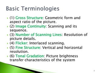
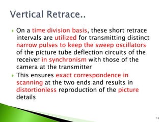
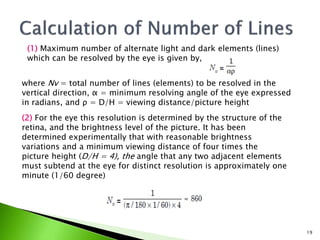
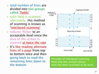
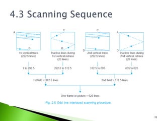
Prof. Minakshi P. Atre
PVG’s College of Engg. & Tech.
1
 (1) Gross Structure: Geometric form and
aspect ratio of the picture.
 (2) Image Continuity: Scanning and its
sequence.
 (3) Number of Scanning Lines: Resolution of
picture details.
 (4) Flicker: Interlaced scanning.
 (5) Fine Structure: Vertical and horizontal
resolution.
 (6) Tonal Gradation: Picture brightness
transfer characteristics of the system
2
 Frame adopted is rectangular
 Width to height ratio, aspect ratio is 4:3
 Why larger width? Motion occurs in horizontal
plane rather than vertical plane
 eyes can view with more ease and comfort
when the width of a picture is more than its
height
 usage of rectangular frame in motion pictures
with a width/height ratio of 4/3 is another
important reason for adopting this shape and
aspect ratio continued..
3
 Not essential that size of picture produced and
picture televised be same but
 it is essential that the aspect ratio of the two be
same, otherwise the scene details would look too
thin or too wide
 same coordinates should be scanned at any instant
both by the camera tube beam and the picture tube
beam in the receiver-this results into
synchronization process
 Synchronizing pulses are transmitted along with
the picture information to achieve exact
congruence between transmitter and receiver
scanning systems
4
 Scanning is to create an illusion of continuity
 Motion in the picture should appear smooth
and continuous
 Principle used for this is: persistence of vision
or storage characteristics of human eye
 Sensation by incident light does not cease
immediately after the light is removed but
persists for about 1/16th of a second, this is
called as persistence of vision
continued..
5
 Thus if the scanning rate per second is made
greater than sixteen, or the number of
pictures shown per second is more than
sixteen, the eye is able to integrate the
changing levels of brightness in the scene
 Picture elements scanned rapidly enough to
appear as complete picture to the eye
 Motion pictures use 24 still pictures per
second and they are shown rapidly to
produce the continuity continued..
6
 Process of scanning using persistence of vision:
A shutter in the projector rotates in front of the
light source and allows the film to be projected
on the screen when the film frame is still, but
blanks out any light from the screen during the
time when the next film frame is being moved
into position
 a rapid succession of still-film frames is seen on
the screen
 With all light removed during the change from
one frame to the next, the eye sees a rapid
sequence of still pictures that provides the
illusion of continuous motion
7
 Scanning :
 Horizontal scanning
 Vertical scanning
8
 Trace & retrace
 Trace-from left to right
 Linear rise in horizontal
deflection coil current
 Uniform & continuous
motion
 At peak of rise, sawtooth
wave reverses direction and
decreases rapidly to its
initial value
 fast reversal produces the
retrace or flyback
 start of the horizontal trace
is at the left edge of the
raster
 finish is at the right edge,
where the flyback produces
retrace back to the left edge
9
10
 sawtooth current in the vertical deflection
coils
 moves the electron beam from top to bottom
of the raster
 at uniform speed while the electron beam is
being deflected horizontally
 beam produces complete horizontal lines one
below the other while moving from top to
bottom
11
 Trace deflects beam to
the bottom of raster
 Rapid vertical retrace
reflects the beam to
top
 maximum amplitude of
the vertical sweep
current brings the
beam to the bottom
12
 during vertical retrace the horizontal scanning continues
 several lines get scanned during this period
 information or brightness at the top of the target plate or
picture tube screen normally changes by the time the
beam returns to the top to recommence the whole process
 This information is picked up during the next scanning
cycle and the whole process is repeated 25 times to cause
an illusion of continuity
 actual scanning sequence is however a little more
complex than that just described and is explained
 during horizontal retrace and vertical retrace intervals the
scanning beams at the camera tube and picture tube are
blanked and no picture information is either picked up or
reproduced
13
14
 On a time division basis, these short retrace
intervals are utilized for transmitting distinct
narrow pulses to keep the sweep oscillators
of the picture tube deflection circuits of the
receiver in synchronism with those of the
camera at the transmitter
 This ensures exact correspondence in
scanning at the two ends and results in
distortionless reproduction of the picture
details
15
 Most scenes have brightness gradations in
the vertical direction
 WHY SCANNING LINES IMPORTANT?
Ability of the scanning beam to allow
reproduction of electrical signals according to
these variations and the capability of the
human eye to resolve these distinctly, while
viewing the reproduced picture, depends on
the total number of lines employed for
scanning
16
17
 Consider fig.-alternate B & W lines
 If the thickness of the scanning beam is equal
to the width of each white and black bar, and
the number of scanning lines is chosen equal
to the number of bars, the electrical
information corresponding to the brightness
of each bar will be correctly reproduced
during the scanning process
 But greater the number of lines, greater will
be the resolution
 However, total number of lines that need be
employed is limited by the resolving
capability of the human eye at the minimum
viewing distance
18
(1) Maximum number of alternate light and dark elements (lines)
which can be resolved by the eye is given by,
where Nv = total number of lines (elements) to be resolved in the
vertical direction, α = minimum resolving angle of the eye expressed
in radians, and ρ = D/H = viewing distance/picture height
(2) For the eye this resolution is determined by the structure of the
retina, and the brightness level of the picture. It has been
determined experimentally that with reasonable brightness
variations and a minimum viewing distance of four times the
picture height (D/H = 4), the angle that any two adjacent elements
must subtend at the eye for distinct resolution is approximately one
minute (1/60 degree)
19
 (3) Thus if the total number of scanning lines
is chosen close to 860 and the scanning
beam just passes over each bar (line)
separately while scanning all the lines from
top to bottom of the picture frame, a distinct
pick up of the picture information results and
this is the best that can be expected from the
system. This perhaps explains the use of 819
lines in the original French TV system.
20
 (4) Concept of Kell Factor : In practice, the picture
elements are not arranged as equally spaced
segments but have random distribution of black,
grey and white depending on the nature of the
picture details
 Statistical analysis and subjective tests carried out
to determine the average number of effective lines
suggest that about 70 per cent of the total lines or
segments get separately scanned in the vertical
direction and the remaining 30 percent get
merged with other elements due to the beam spot
falling equally on two consecutive lines
 Thus the effective number of lines distinctly
resolved, i.e., Nr = Nv × k, where k is the
resolution factor whose value lies between 0.65 to
0.75. Assuming the value of k = 0.7 we get, Nr =
Nv × k = 860 × 0.7 = 602
21
 Tests with observers : Though the eye can detect the
effective sharpness provided by about 800 scanning
lines, but the improvement is not very significant with
line numbers greater than 500 while viewing pictures
having motion
 Channel Bandwidth : increases with increase in
number of lines and this not only adds to the cost of
the system but also reduces the number of television
channels that can be provided in a given VHF or UHF
transmission band
 Thus as a compromise between quality and cost, the
total number of lines inclusive of those lost during
vertical retrace has been chosen to be 625 in the
625-B monochrome TV system
22
 525 line American system, the total number
of lines has been fixed at 525 because of a
somewhat higher scanning rate employed in
this system
23
What is flicker ?
 The rate of 24 pictures per second in motion
pictures and that of scanning 25 frames per
second in television pictures is enough to cause
an illusion of continuity, they are not rapid
enough to allow the brightness of one picture or
frame to blend smoothly into the next through
the time when the screen is blanked between
successive frames.
 This results in a definite flicker of light that is
very annoying to the observer when the screen is
made alternately bright and dark
24
 Solution to avoid flicker : It’s solved in motion
pictures by showing each picture twice, so that
48 views of the scene are shown per second
although there are still the same 24 picture
frames per second. As a result of the increased
blanking rate, flicker is eliminated
Concepts introduced in flicker :
 4.1 Interlaced scanning
 4.2 Scanning periods
 4.3 Scanning sequence
25
 An effective rate of 50 vertical scans per
second is utilized to reduce flicker in TV
 Accomplished by increasing the downward
rate of travel of the scanning electron beam,
so that every alternate line gets scanned
instead of every successive line
 When the beam reaches the bottom of the
picture frame, it quickly returns to the top to
scan those lines those were missed in
previous scanning
26
 total number of lines are
divided into two groups
called ‘fields’
 each field is scanned
alternately, this method
of scanning is known as
‘interlaced scanning’
 reduces flicker to an
acceptable level since the
area of the screen is
covered at twice the rate
 It’s like reading alternate
lines of a page from top
to bottom once and then
going back to read the
remaining lines down to
the bottom
Principle of interlaced scanning.
Note that the vertical retrace
time has been assumed to be zero.
27
 625 lines of each frame or picture are divided
into sets of 312.5 lines and each set is scanned
alternately to cover the entire picture area
 To achieve this the horizontal sweep oscillator is
made to work at a frequency of 15625 Hz (312.5
× 50 = 15625) to scan the same number of lines
per frame (15625/25 = 625 lines)
 But the vertical sweep circuit is run at a
frequency of 50 instead of 25 Hz
 since the beam is now deflected from top to
bottom in half the time and the horizontal
oscillator is still operating at 15625 Hz, only half
the total lines, i.e., 312.5 (625/2 = 312.5) get
scanned during each vertical sweep
28
 first field ends in a half line and the second field
commences at middle of the line on the top of
the target plate or screen
 the beam is able to scan the remaining 312.5
alternate lines during its downward journey
 the beam scans 625 lines (312.5 × 2 = 625) per
frame at the same rate of 15625 lines (312.5 ×
50 = 15625) per second
 with interlaced scanning the flicker effect is
eliminated without increasing the speed of
scanning, which in turn does not need any
increase in the channel bandwidth
29
 frame repetition rate of 25 : chosen to make the
field frequency equal to the power line frequency
of 50 Hz-reduces the undesired effects of hum
due to pickup from the mains
 such effects in the picture stay still, instead of
drifting up or down on the screen
 American TV system: a field frequency of 60 was
adopted because the supply frequency is 60 Hz
in USA
 the total number of lines scanned per second
((525/2) × 60 = 15750) lines to practically the
same as in the 625 line system
30
 Horizontal Sweep Currents:
Horizontal line period is 64 μs (106/15625 = 64
μs), out of which the active line period is 52 μs and
the remaining 12 μs is the line blanking period
Beam returns during this short interval to the
extreme left side of the frame to start tracing the
next line
31
 Vertical Sweep Currents :
Field frequency set at 50 Hz, the duration of the vertical trace is
20 ms (1/50 = 20 ms).
Out of this period of 20 ms, 18.720 ms are spent in bringing the
beam from top to bottom and the remaining 1.280 ms is taken
by the beam to return back to the top to commence the next
cycle
32
 Retrace times involved (both horizontal and
vertical) are due to physical limitations of
practical scanning systems
 are not utilized for transmitting or receiving any
video signal
 horizontal and vertical sweep oscillators operate
continuously to achieve the fast sequence of
interlaced scanning, 20 horizontal lines get
traced during each vertical retrace interval
33
 40 scanning lines are lost per frame, as
blanked lines during the retrace interval of
two fields
 This leaves the active number of lines, Na, for
scanning the picture details equal to 625 – 40
= 585, instead of the 625 lines actually
scanned per frame
34
35
 Lines are numbered in the sequence in which
these are actually scanned
 During the first vertical trace actually 292.5
lines are scanned
 Beam starts at A, and sweeps across the
frame with uniform velocity to cover all the
picture elements in one horizontal line
 At the end of this trace the beam then
retraces rapidly to the left side of the frame
as shown by the dashed line in the illustration
to begin the next horizontal line
36
 horizontal lines slope downwards in the
direction of scanning because the vertical
deflecting current simultaneously produces a
vertical scanning motion, which is very slow
compared with horizontal scanning
 Slope of the horizontal trace from left to right
is greater than during retrace from right to
left
 Reason: Faster retrace does not allow the
beam so much time to be deflected vertically
37
 After line one, the beam is at the left side ready
to scan line 3, omitting the second line
 However, it is convenient to number the lines as
they are scanned and so the next scanned line
skipping one line, is numbered two and not three
 This process continues till the last line gets
scanned half when the vertical motion reaches
the bottom of the raster or frame
 Skipping of lines is accomplished by doubling the
vertical scanning frequency from the frame or
picture repetition rate of 25 to the field
frequency of 50 Hz
38
 With the field frequency of 50 Hz the height of
the raster is so set that 292.5 lines get scanned
as the beam travels from top to bottom and
reaches point B
 Retrace: retrace starts and takes a period equal
to 20 horizontal line periods to reach the top
marked C
 These 20 lines are known as inactive lines, as the
scanning beam is cut-off during this period
 Thus the second field starts at the middle of the
raster and the first line scanned is the 2nd half of
line number 313
 scanning of second field, starting at the middle
of the raster automatically enables the beam to
scan the alternative lines left unscanned during
the first field
39
 vertical scanning motion otherwise is exactly
the same as in the previous field giving all the
horizontal lines the same slope downwards in
the direction of scanning
 As a result 292.5 lines again get scanned and
the beam reaches the bottom of the frame
when it has completed full scanning of line
number 605
 The inactive vertical retrace again begins and
brings the beam back to the top at point A in
a period during which 20 blanked horizontal
lines (605 to 625) get scanned
40
 Back at point A, the scanning beam has just
completed two fields or one frame and is
ready to start the third field covering the
same area (no. of lines) as scanned during the
first field
 This process (of scanning fields) is continued
at a fast rate of 50 times a second, which not
only creates an illusion of continuity but also
solves the problem of flicker satisfactorily.
41
 Definition : Ability of the image reproducing
system to represent the fine structure of an
object is known as its resolving power or
resolution
 Two sub components :
* Vertical resolution
* Horizontal resolution
 Vertical Resolution :
Def: The extent to which the scanning system is
capable of resolving picture details in the vertical
direction is referred to as its vertical resolution
42
 vertical resolution is a function of the
scanning lines into which the picture is
divided in the vertical plane
 vertical resolution in the 625 lines system can
then be expressed as Vr = Na × k
where Vr is the vertical resolution
expressed in number of lines, Na is the active
number of lines and k is the resolution factor
(also known as Kell factor)
 Assuming a reasonable value of k = 0.69,
 Vr = 585 × 0.69 = 400 lines
43
 the corresponding resolution of 35 mm
motion pictures is about 515 lines and thus
produces greater details as compared to
television pictures
44
45
46
 Definition : The capability of the system to
resolve maximum number of picture
elements along the scanning lines determines
horizontal resolution
 can be evaluated by considering a vertical bar
pattern as shown in Fig 2.7
 It would be realistic to aim at equal vertical
and horizontal resolution and as such the
number of alternate black and white bars that
should be considered is equal to
 Na × aspect ratio = 585 × 4/3 = 780
47
 the effective number of alternate black and
white segments in one
 horizontal line for equal vertical and
horizontal resolution are :
 N = Na × aspect ratio × k = 585 × 4/3 ×
0.69 = 533
48
Along one line there are 533/2 ≈ 267 complete cyclic changes,
267 complete square wave cycles get generated during the time
the beam takes to travel along the width of the pattern
Thus the time duration ‘th’ of one square wave cycle is equal to
49
50
 the signal-transmission system should have
proper transfer characteristics to preserve same
brightness gradation as the eye would perceive
when viewing the scene directly
 Any non-linearity in the pick-up and picture tube
should also be corrected by providing inverse
nonlinearities in the channel circuitry to obtain
overall linear characteristics
 sensation in the eye to detect changes or
brightness is logarithmic in nature and this must
be taken into account while designing the overall
channel
51
 (a) Contrast: This is the difference in intensity
between black and white parts of the picture over
and above the brightness level.
 (b) Contrast ratio: The ratio of maximum to
minimum brightness relative to the original
picture is called contrast ratio.
 In broad daylight the variations in brightness are
very wide with ratio as high as 10000 : 1,
whereas the picture tube, because of certain
limitations, cannot produce a contrast with
variations more than 50 : 1 or at most 100 : 1.
52
 Ratio of brightness variations in the
reproduced picture on the screen of the
picture tube, to the brightness variations in
the original scene is known as Gamma of the
picture
 Its value is close to 0.5.
 Another factor which makes stringent
demands from the system unnecessary is the
fact that our eye can accommodate not more
than 10 : 1 variations of light intensity at any
time
53
 (c) Viewing distance: The viewing distance from the
screen of the TV receiver should not be so large that
the eye cannot resolve details of the picture.
 The distance should also not be so small that picture
elements become separately visible.
 The above conditions are met when the vertical
picture size subtends an angle of approximately 15°
at the eye
 The distance also depends on habit, varies from
person to person, and lies between 3 to 8 times the
picture height.
 Most people prefer a distance close to five times the
picture height
 While viewing TV, a small light should be kept on in
the room to reduce contrast. This does not strain the
eyes and there is less fatigue
54

Basic terminologies of television

  • 1.
    Prof. Minakshi P.Atre PVG’s College of Engg. & Tech. 1
  • 2.
     (1) GrossStructure: Geometric form and aspect ratio of the picture.  (2) Image Continuity: Scanning and its sequence.  (3) Number of Scanning Lines: Resolution of picture details.  (4) Flicker: Interlaced scanning.  (5) Fine Structure: Vertical and horizontal resolution.  (6) Tonal Gradation: Picture brightness transfer characteristics of the system 2
  • 3.
     Frame adoptedis rectangular  Width to height ratio, aspect ratio is 4:3  Why larger width? Motion occurs in horizontal plane rather than vertical plane  eyes can view with more ease and comfort when the width of a picture is more than its height  usage of rectangular frame in motion pictures with a width/height ratio of 4/3 is another important reason for adopting this shape and aspect ratio continued.. 3
  • 4.
     Not essentialthat size of picture produced and picture televised be same but  it is essential that the aspect ratio of the two be same, otherwise the scene details would look too thin or too wide  same coordinates should be scanned at any instant both by the camera tube beam and the picture tube beam in the receiver-this results into synchronization process  Synchronizing pulses are transmitted along with the picture information to achieve exact congruence between transmitter and receiver scanning systems 4
  • 5.
     Scanning isto create an illusion of continuity  Motion in the picture should appear smooth and continuous  Principle used for this is: persistence of vision or storage characteristics of human eye  Sensation by incident light does not cease immediately after the light is removed but persists for about 1/16th of a second, this is called as persistence of vision continued.. 5
  • 6.
     Thus ifthe scanning rate per second is made greater than sixteen, or the number of pictures shown per second is more than sixteen, the eye is able to integrate the changing levels of brightness in the scene  Picture elements scanned rapidly enough to appear as complete picture to the eye  Motion pictures use 24 still pictures per second and they are shown rapidly to produce the continuity continued.. 6
  • 7.
     Process ofscanning using persistence of vision: A shutter in the projector rotates in front of the light source and allows the film to be projected on the screen when the film frame is still, but blanks out any light from the screen during the time when the next film frame is being moved into position  a rapid succession of still-film frames is seen on the screen  With all light removed during the change from one frame to the next, the eye sees a rapid sequence of still pictures that provides the illusion of continuous motion 7
  • 8.
     Scanning : Horizontal scanning  Vertical scanning 8
  • 9.
     Trace &retrace  Trace-from left to right  Linear rise in horizontal deflection coil current  Uniform & continuous motion  At peak of rise, sawtooth wave reverses direction and decreases rapidly to its initial value  fast reversal produces the retrace or flyback  start of the horizontal trace is at the left edge of the raster  finish is at the right edge, where the flyback produces retrace back to the left edge 9
  • 10.
  • 11.
     sawtooth currentin the vertical deflection coils  moves the electron beam from top to bottom of the raster  at uniform speed while the electron beam is being deflected horizontally  beam produces complete horizontal lines one below the other while moving from top to bottom 11
  • 12.
     Trace deflectsbeam to the bottom of raster  Rapid vertical retrace reflects the beam to top  maximum amplitude of the vertical sweep current brings the beam to the bottom 12
  • 13.
     during verticalretrace the horizontal scanning continues  several lines get scanned during this period  information or brightness at the top of the target plate or picture tube screen normally changes by the time the beam returns to the top to recommence the whole process  This information is picked up during the next scanning cycle and the whole process is repeated 25 times to cause an illusion of continuity  actual scanning sequence is however a little more complex than that just described and is explained  during horizontal retrace and vertical retrace intervals the scanning beams at the camera tube and picture tube are blanked and no picture information is either picked up or reproduced 13
  • 14.
  • 15.
     On atime division basis, these short retrace intervals are utilized for transmitting distinct narrow pulses to keep the sweep oscillators of the picture tube deflection circuits of the receiver in synchronism with those of the camera at the transmitter  This ensures exact correspondence in scanning at the two ends and results in distortionless reproduction of the picture details 15
  • 16.
     Most sceneshave brightness gradations in the vertical direction  WHY SCANNING LINES IMPORTANT? Ability of the scanning beam to allow reproduction of electrical signals according to these variations and the capability of the human eye to resolve these distinctly, while viewing the reproduced picture, depends on the total number of lines employed for scanning 16
  • 17.
  • 18.
     Consider fig.-alternateB & W lines  If the thickness of the scanning beam is equal to the width of each white and black bar, and the number of scanning lines is chosen equal to the number of bars, the electrical information corresponding to the brightness of each bar will be correctly reproduced during the scanning process  But greater the number of lines, greater will be the resolution  However, total number of lines that need be employed is limited by the resolving capability of the human eye at the minimum viewing distance 18
  • 19.
    (1) Maximum numberof alternate light and dark elements (lines) which can be resolved by the eye is given by, where Nv = total number of lines (elements) to be resolved in the vertical direction, α = minimum resolving angle of the eye expressed in radians, and ρ = D/H = viewing distance/picture height (2) For the eye this resolution is determined by the structure of the retina, and the brightness level of the picture. It has been determined experimentally that with reasonable brightness variations and a minimum viewing distance of four times the picture height (D/H = 4), the angle that any two adjacent elements must subtend at the eye for distinct resolution is approximately one minute (1/60 degree) 19
  • 20.
     (3) Thusif the total number of scanning lines is chosen close to 860 and the scanning beam just passes over each bar (line) separately while scanning all the lines from top to bottom of the picture frame, a distinct pick up of the picture information results and this is the best that can be expected from the system. This perhaps explains the use of 819 lines in the original French TV system. 20
  • 21.
     (4) Conceptof Kell Factor : In practice, the picture elements are not arranged as equally spaced segments but have random distribution of black, grey and white depending on the nature of the picture details  Statistical analysis and subjective tests carried out to determine the average number of effective lines suggest that about 70 per cent of the total lines or segments get separately scanned in the vertical direction and the remaining 30 percent get merged with other elements due to the beam spot falling equally on two consecutive lines  Thus the effective number of lines distinctly resolved, i.e., Nr = Nv × k, where k is the resolution factor whose value lies between 0.65 to 0.75. Assuming the value of k = 0.7 we get, Nr = Nv × k = 860 × 0.7 = 602 21
  • 22.
     Tests withobservers : Though the eye can detect the effective sharpness provided by about 800 scanning lines, but the improvement is not very significant with line numbers greater than 500 while viewing pictures having motion  Channel Bandwidth : increases with increase in number of lines and this not only adds to the cost of the system but also reduces the number of television channels that can be provided in a given VHF or UHF transmission band  Thus as a compromise between quality and cost, the total number of lines inclusive of those lost during vertical retrace has been chosen to be 625 in the 625-B monochrome TV system 22
  • 23.
     525 lineAmerican system, the total number of lines has been fixed at 525 because of a somewhat higher scanning rate employed in this system 23
  • 24.
    What is flicker?  The rate of 24 pictures per second in motion pictures and that of scanning 25 frames per second in television pictures is enough to cause an illusion of continuity, they are not rapid enough to allow the brightness of one picture or frame to blend smoothly into the next through the time when the screen is blanked between successive frames.  This results in a definite flicker of light that is very annoying to the observer when the screen is made alternately bright and dark 24
  • 25.
     Solution toavoid flicker : It’s solved in motion pictures by showing each picture twice, so that 48 views of the scene are shown per second although there are still the same 24 picture frames per second. As a result of the increased blanking rate, flicker is eliminated Concepts introduced in flicker :  4.1 Interlaced scanning  4.2 Scanning periods  4.3 Scanning sequence 25
  • 26.
     An effectiverate of 50 vertical scans per second is utilized to reduce flicker in TV  Accomplished by increasing the downward rate of travel of the scanning electron beam, so that every alternate line gets scanned instead of every successive line  When the beam reaches the bottom of the picture frame, it quickly returns to the top to scan those lines those were missed in previous scanning 26
  • 27.
     total numberof lines are divided into two groups called ‘fields’  each field is scanned alternately, this method of scanning is known as ‘interlaced scanning’  reduces flicker to an acceptable level since the area of the screen is covered at twice the rate  It’s like reading alternate lines of a page from top to bottom once and then going back to read the remaining lines down to the bottom Principle of interlaced scanning. Note that the vertical retrace time has been assumed to be zero. 27
  • 28.
     625 linesof each frame or picture are divided into sets of 312.5 lines and each set is scanned alternately to cover the entire picture area  To achieve this the horizontal sweep oscillator is made to work at a frequency of 15625 Hz (312.5 × 50 = 15625) to scan the same number of lines per frame (15625/25 = 625 lines)  But the vertical sweep circuit is run at a frequency of 50 instead of 25 Hz  since the beam is now deflected from top to bottom in half the time and the horizontal oscillator is still operating at 15625 Hz, only half the total lines, i.e., 312.5 (625/2 = 312.5) get scanned during each vertical sweep 28
  • 29.
     first fieldends in a half line and the second field commences at middle of the line on the top of the target plate or screen  the beam is able to scan the remaining 312.5 alternate lines during its downward journey  the beam scans 625 lines (312.5 × 2 = 625) per frame at the same rate of 15625 lines (312.5 × 50 = 15625) per second  with interlaced scanning the flicker effect is eliminated without increasing the speed of scanning, which in turn does not need any increase in the channel bandwidth 29
  • 30.
     frame repetitionrate of 25 : chosen to make the field frequency equal to the power line frequency of 50 Hz-reduces the undesired effects of hum due to pickup from the mains  such effects in the picture stay still, instead of drifting up or down on the screen  American TV system: a field frequency of 60 was adopted because the supply frequency is 60 Hz in USA  the total number of lines scanned per second ((525/2) × 60 = 15750) lines to practically the same as in the 625 line system 30
  • 31.
     Horizontal SweepCurrents: Horizontal line period is 64 μs (106/15625 = 64 μs), out of which the active line period is 52 μs and the remaining 12 μs is the line blanking period Beam returns during this short interval to the extreme left side of the frame to start tracing the next line 31
  • 32.
     Vertical SweepCurrents : Field frequency set at 50 Hz, the duration of the vertical trace is 20 ms (1/50 = 20 ms). Out of this period of 20 ms, 18.720 ms are spent in bringing the beam from top to bottom and the remaining 1.280 ms is taken by the beam to return back to the top to commence the next cycle 32
  • 33.
     Retrace timesinvolved (both horizontal and vertical) are due to physical limitations of practical scanning systems  are not utilized for transmitting or receiving any video signal  horizontal and vertical sweep oscillators operate continuously to achieve the fast sequence of interlaced scanning, 20 horizontal lines get traced during each vertical retrace interval 33
  • 34.
     40 scanninglines are lost per frame, as blanked lines during the retrace interval of two fields  This leaves the active number of lines, Na, for scanning the picture details equal to 625 – 40 = 585, instead of the 625 lines actually scanned per frame 34
  • 35.
  • 36.
     Lines arenumbered in the sequence in which these are actually scanned  During the first vertical trace actually 292.5 lines are scanned  Beam starts at A, and sweeps across the frame with uniform velocity to cover all the picture elements in one horizontal line  At the end of this trace the beam then retraces rapidly to the left side of the frame as shown by the dashed line in the illustration to begin the next horizontal line 36
  • 37.
     horizontal linesslope downwards in the direction of scanning because the vertical deflecting current simultaneously produces a vertical scanning motion, which is very slow compared with horizontal scanning  Slope of the horizontal trace from left to right is greater than during retrace from right to left  Reason: Faster retrace does not allow the beam so much time to be deflected vertically 37
  • 38.
     After lineone, the beam is at the left side ready to scan line 3, omitting the second line  However, it is convenient to number the lines as they are scanned and so the next scanned line skipping one line, is numbered two and not three  This process continues till the last line gets scanned half when the vertical motion reaches the bottom of the raster or frame  Skipping of lines is accomplished by doubling the vertical scanning frequency from the frame or picture repetition rate of 25 to the field frequency of 50 Hz 38
  • 39.
     With thefield frequency of 50 Hz the height of the raster is so set that 292.5 lines get scanned as the beam travels from top to bottom and reaches point B  Retrace: retrace starts and takes a period equal to 20 horizontal line periods to reach the top marked C  These 20 lines are known as inactive lines, as the scanning beam is cut-off during this period  Thus the second field starts at the middle of the raster and the first line scanned is the 2nd half of line number 313  scanning of second field, starting at the middle of the raster automatically enables the beam to scan the alternative lines left unscanned during the first field 39
  • 40.
     vertical scanningmotion otherwise is exactly the same as in the previous field giving all the horizontal lines the same slope downwards in the direction of scanning  As a result 292.5 lines again get scanned and the beam reaches the bottom of the frame when it has completed full scanning of line number 605  The inactive vertical retrace again begins and brings the beam back to the top at point A in a period during which 20 blanked horizontal lines (605 to 625) get scanned 40
  • 41.
     Back atpoint A, the scanning beam has just completed two fields or one frame and is ready to start the third field covering the same area (no. of lines) as scanned during the first field  This process (of scanning fields) is continued at a fast rate of 50 times a second, which not only creates an illusion of continuity but also solves the problem of flicker satisfactorily. 41
  • 42.
     Definition :Ability of the image reproducing system to represent the fine structure of an object is known as its resolving power or resolution  Two sub components : * Vertical resolution * Horizontal resolution  Vertical Resolution : Def: The extent to which the scanning system is capable of resolving picture details in the vertical direction is referred to as its vertical resolution 42
  • 43.
     vertical resolutionis a function of the scanning lines into which the picture is divided in the vertical plane  vertical resolution in the 625 lines system can then be expressed as Vr = Na × k where Vr is the vertical resolution expressed in number of lines, Na is the active number of lines and k is the resolution factor (also known as Kell factor)  Assuming a reasonable value of k = 0.69,  Vr = 585 × 0.69 = 400 lines 43
  • 44.
     the correspondingresolution of 35 mm motion pictures is about 515 lines and thus produces greater details as compared to television pictures 44
  • 45.
  • 46.
  • 47.
     Definition :The capability of the system to resolve maximum number of picture elements along the scanning lines determines horizontal resolution  can be evaluated by considering a vertical bar pattern as shown in Fig 2.7  It would be realistic to aim at equal vertical and horizontal resolution and as such the number of alternate black and white bars that should be considered is equal to  Na × aspect ratio = 585 × 4/3 = 780 47
  • 48.
     the effectivenumber of alternate black and white segments in one  horizontal line for equal vertical and horizontal resolution are :  N = Na × aspect ratio × k = 585 × 4/3 × 0.69 = 533 48
  • 49.
    Along one linethere are 533/2 ≈ 267 complete cyclic changes, 267 complete square wave cycles get generated during the time the beam takes to travel along the width of the pattern Thus the time duration ‘th’ of one square wave cycle is equal to 49
  • 50.
  • 51.
     the signal-transmissionsystem should have proper transfer characteristics to preserve same brightness gradation as the eye would perceive when viewing the scene directly  Any non-linearity in the pick-up and picture tube should also be corrected by providing inverse nonlinearities in the channel circuitry to obtain overall linear characteristics  sensation in the eye to detect changes or brightness is logarithmic in nature and this must be taken into account while designing the overall channel 51
  • 52.
     (a) Contrast:This is the difference in intensity between black and white parts of the picture over and above the brightness level.  (b) Contrast ratio: The ratio of maximum to minimum brightness relative to the original picture is called contrast ratio.  In broad daylight the variations in brightness are very wide with ratio as high as 10000 : 1, whereas the picture tube, because of certain limitations, cannot produce a contrast with variations more than 50 : 1 or at most 100 : 1. 52
  • 53.
     Ratio ofbrightness variations in the reproduced picture on the screen of the picture tube, to the brightness variations in the original scene is known as Gamma of the picture  Its value is close to 0.5.  Another factor which makes stringent demands from the system unnecessary is the fact that our eye can accommodate not more than 10 : 1 variations of light intensity at any time 53
  • 54.
     (c) Viewingdistance: The viewing distance from the screen of the TV receiver should not be so large that the eye cannot resolve details of the picture.  The distance should also not be so small that picture elements become separately visible.  The above conditions are met when the vertical picture size subtends an angle of approximately 15° at the eye  The distance also depends on habit, varies from person to person, and lies between 3 to 8 times the picture height.  Most people prefer a distance close to five times the picture height  While viewing TV, a small light should be kept on in the room to reduce contrast. This does not strain the eyes and there is less fatigue 54