1. Television works by transmitting picture information over an electric channel through scanning and converting optical information into electrical signals.
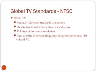
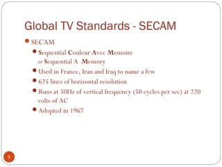
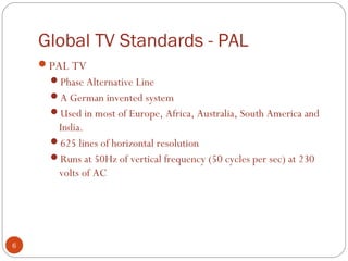
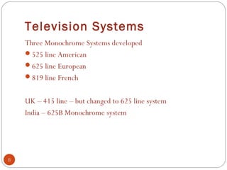
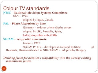
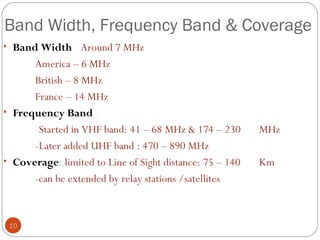
2. There are different global TV standards including NTSC, PAL, and SECAM which use different line resolutions and frequencies. In India, the PAL 625 line system is used.
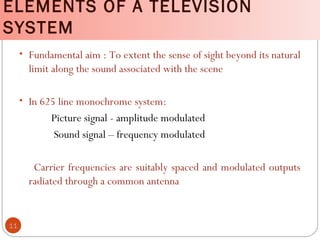
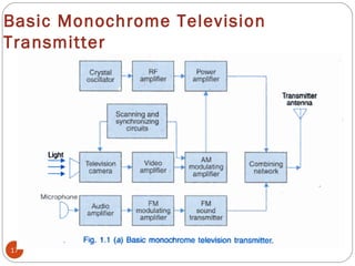
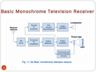
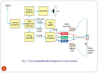
3. A television system consists of cameras that convert scenes into electrical signals, transmitters that broadcast the signals over radio waves, and receivers that convert the signals back into images on screens.