Downloaded 1,083 times
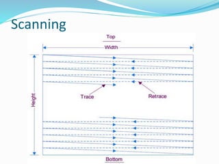
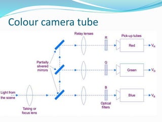
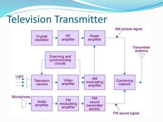
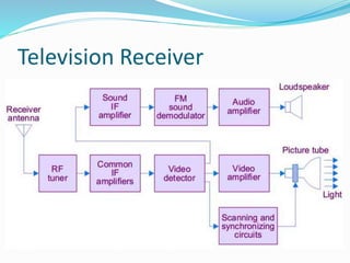
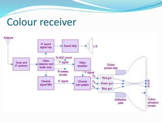
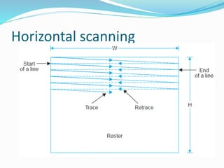
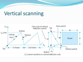
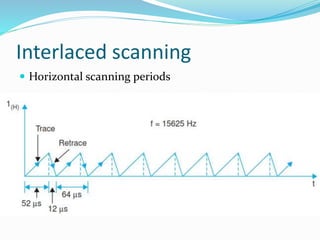
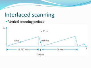
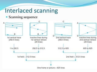
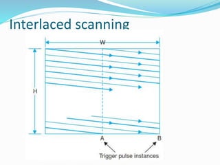
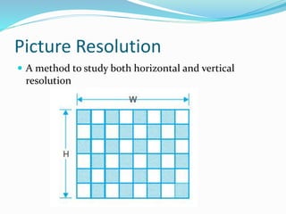

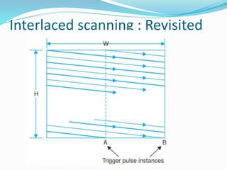
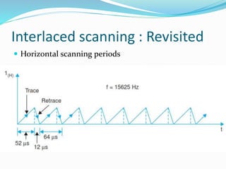
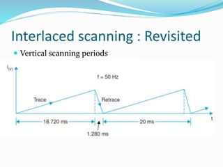
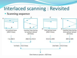
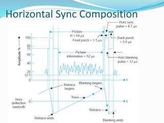
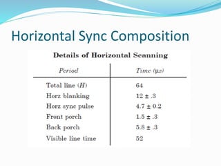
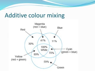


The document covers the fundamentals of video signals, detailing aspects of picture transmission, synchronization, and receiver controls necessary for effective television broadcasting. It discusses technical elements such as scanning, resolution, brightness, contrast, and the composite video signal composition. Key topics include horizontal and vertical scanning processes, the importance of synchronization pulses, and the roles of luminance, hue, and saturation in color transmission.


![Tv 101[1]](https://cdn.slidesharecdn.com/ss_thumbnails/tv1011-12648274753543-phpapp01-thumbnail.jpg?width=640&height=640&fit=bounds)


