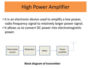
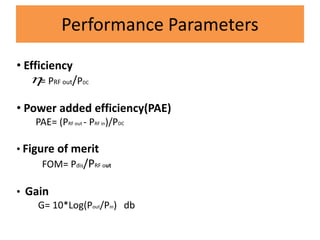
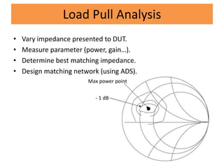
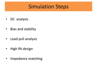
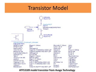
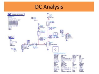
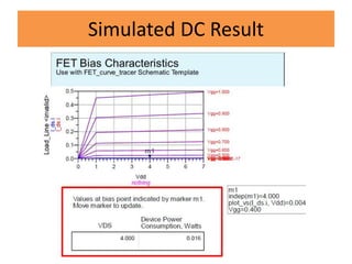
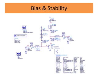
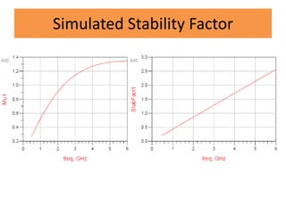
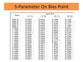
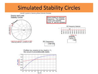
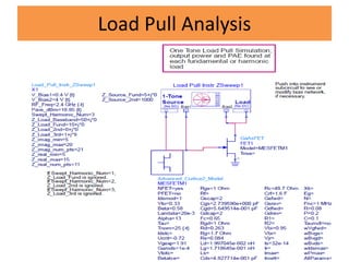
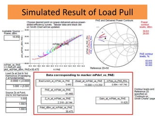
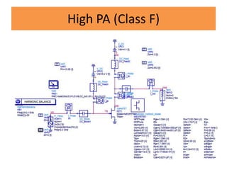
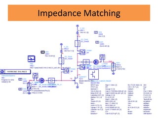
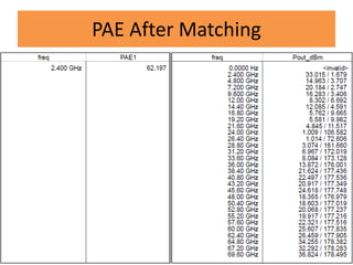
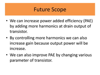
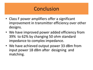
This document summarizes a project to simulate a class F power amplifier operating at 2.4 GHz using ADS software. The objectives were to achieve over 50% power added efficiency and output power over 30 dBm. It provides background on power amplifiers and performance parameters. It describes the simulation steps taken, including DC analysis, stability analysis, load pull analysis, and impedance matching. The simulations achieved 62% power added efficiency and 33 dBm output power. Future work and conclusions are also presented.


![References
[1] P. Colantonio, F. Giannini, E. Limiti, “High efficiency RF and microwave
solid state power amplifier”, John Wiley & Sons, Ltd, 2009
[2] Steve C. Cripps, RF power amplifier for wireless comm.(2nd edition) ,artech
house microwave library
[3] Class D Audio Amplifier with Ferroxcube Gapped Toroid Output Filter,
Ferroxcube - Ferrite Cores, Bobbins & Accessories. Web. 13 May 2010.
[4] M. Hayati, A. Lotfi, M. Kazimierczuk, and H. Sekiya, “Performance
study of class-e power amplifier with a shunt inductor at subnominal
condition,” IEEE Trans. Power Electron., vol. 28, no. 8, pp. 3834–3844,
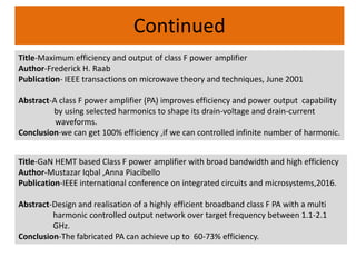
[5] F. H. Raab, “Maximum efficiency and output of Class-F power amplifiers”,
IEEE Transactions on Microwave Theory and Techniques, Vol. 49, No. 6,
June 2001](https://image.slidesharecdn.com/poweramplifierppt-170527141749/85/Power-amplifier-ppt-34-320.jpg)
![Continued
[6] F. H. Raab, “An introduction to Class-F power amplifiers,” RF Design, Vol.
19, No. 5, pp. 79-84, May 1996.
[7] N. Tuffy, G. Lei, Z. Anding, and T. J. Brazil, "A simplified broadband
design methodology for linearized high-efficiency continuous Class-F
power amplifiers," IEEE Trans. Microw. Theory Tech., vol. 60, pp. 1952-
1963, 2012.
[8] W. Ying, D. Shiwei, Y. Lisheng, L. Zhengjun, D. Yazhou, and F. Wenli,
"Design of high efficiency GaN HEMT class-F power amplifier at Sband,"in
Antennas and Propagation (APCAP), 2014 3rd Asia-Pacific Conference on,
2014, pp. 1157-1158.](https://image.slidesharecdn.com/poweramplifierppt-170527141749/85/Power-amplifier-ppt-35-320.jpg)


![RF Module Design - [Chapter 6] Power Amplifier](https://cdn.slidesharecdn.com/ss_thumbnails/rfch6-150613070347-lva1-app6891-thumbnail.jpg?width=640&height=640&fit=bounds)


![RF Circuit Design - [Ch4-2] LNA, PA, and Broadband Amplifier](https://cdn.slidesharecdn.com/ss_thumbnails/ch4-2-150613064410-lva1-app6891-thumbnail.jpg?width=640&height=640&fit=bounds)


![[IJET-V1I2P6] Authors :Sarat K Kotamraju, K.Ch.Sri Kavya, A.Gnandeep Reddy, G...](https://cdn.slidesharecdn.com/ss_thumbnails/ijet-v1i2p6-150501052009-conversion-gate02-thumbnail.jpg?width=640&height=640&fit=bounds)


