Downloaded 1,662 times


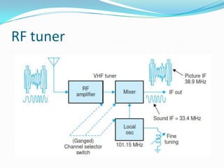


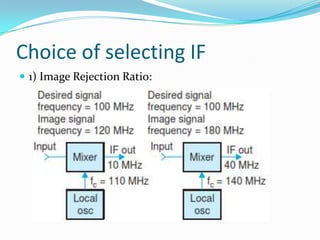
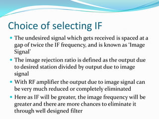


The document details the components and functioning of a television receiver, including RF tuner, video amplifier, sound section, and sync processing. It explains the principles behind selecting intermediate frequencies (IF), deflection circuits, and the processing of luminance and chroma signals for color reproduction. Additionally, it covers the various subsystems involved in signal amplification, demodulation, and overall receiver operation, emphasizing the importance of design considerations for optimal performance.