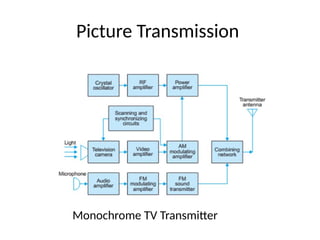
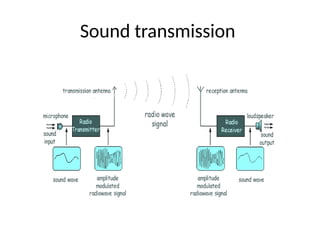
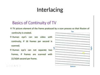
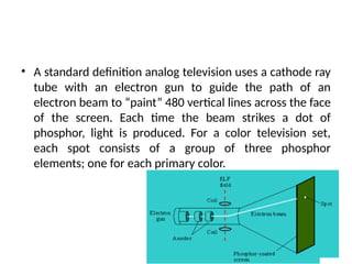
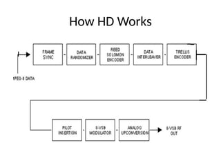
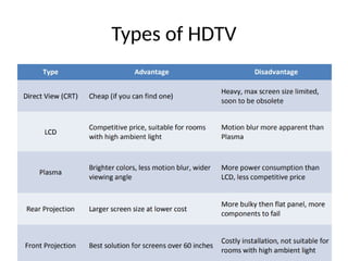
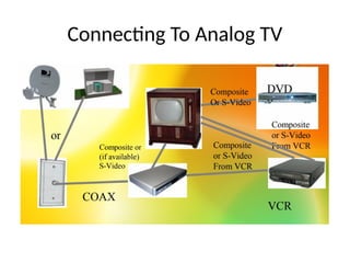
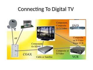
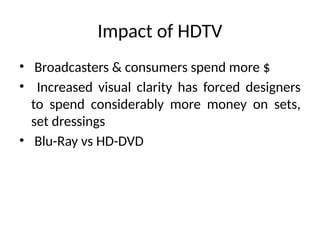
UNIT –II
TELEVISION STSNDARDS AND SYSTEMS
• Components of a TV system
• Interlacing
• Composite video signal
• Color TV
– Luminance and Chrominance Signal
– Monochrome and colour picture tubes
– Color picture tubes
– Color picture tv systems-NTSC ,PAL,SECAM
• Components of a TV Remote control and TV
camera tubes,HDTV,LED,LCD TV,DTH TV
Television
• To see at a distance
• Visual information in the scene is converted to an
electrical video signal for transmission to the receiver
• The image is reassembled on the fluorescent screen of
the picture tube
• In monochrome television ,the picture is reproduced
as shades of white , gray and black
• In color television the picture is reproduced in all their
natural colors as the combination of red green and
blue
Components of TV
• Picture Transmission
• Sound Transmission
• Picture reception
Components of TV
Monochrome TV
ONE ELECTRON GUN
CONTINUOUS PHOSPHOR COATING
Picture Transmission
Monochrome TV Transmitter
Picture transmission tool
Sound transmission
Picture reception
Interlacing
Monochrome TV Receiver
Elements of a Picture Tube
• Electron gun
• Control grid
• Accelerating grid
• Focusing grid
Cross sectional view about the neck of the
picture tube
Picture tube circuit and associated controls
Production of video
signal by
Photoemission
Production of video
signal by
Photoconduction
Cross sectional view of vidicon TV
Circuit for output signal
Leaky capacitor concept
Rear view of monochrome tv receiver
receiver
Function of a composite video signal
Sound signal Separation
Block diagram of AGC System
High voltage (EHT) Supply
Deflection circuit
Path of scanning beam in covering Picture
Area
Waveform of current in the horizontal
deflection coils
Produces Linear scanning in the horizontal direction
INTERLACING
COMPOSITE VIDEO SIGNAL
COLOUR TV PICTURE TUBE
Basics of composite video signal
• In TV Picture signal is a combinational of
multiple signals.
– Camera Signal : Corresponding to the variation of
light of given picture
– Synchronization Pulse : To Provide Synchronization
– Blanking Pulse : To make the retrace invisible
• In TV ,There are 625lines in one frame
– One frame – Divided into two fields 1 to 312.5
lines and 312.5 to 625 lines.
– Again 1st
field from 1to 312.5 divided into trace
292.5 lines (1 to 292.5) and retrace 20 lines(292.5
to 312.5)
– 2nd
field from 312.5 to 625 lines again divided into
trace(292.5 lines(312.5 to 605 lines)retrace 20
lines (605 to 325lines)
Composite video signal
RANGE OF VIDEO SIGNAL
V/VMAX = PERCENTAGE OF SIGNAL
SYNCHRONIZATION
Camera Signal
• Lowest Amplitude at 12.5 % shows whitest
part of the picture.
• Highest amplitude at 75% shows darkest part
of the picture.
• Signal transmission : Negative Polarity
transmission
Horizontal blanking Pulse
• Horizontal blanking pulse (12µs) has three
portion
– Front Porch (1.5 µs) Fly black initiated with black
level
– Horizontal synchronization pulse (4.7µs)
• Synchronization is done to Tx and Rx by Pulse
– Back Porch (5.8 µs)
• Fly back completed with black level.
HORIZONTAL BLANKING
HORIZONTAL BLANKING
BACK PORCH
TRACE and RETRACE
Vertical Synchronization Pulse
• It is of 2.5 line duration
• So it’s time period is 2.5 * 64 =160 µs
• At the end of first field vertical sync pulse is
added at (312.5 to 315 lines)(2.5 lines)
• At the end of second field vertical sync pulse is
added at (1 to 2.5 lines)
• One vertical sync pulse ends at half line period
and one ends at full line period.
Vertical sync pulse 75% to 100 %
Vertical Blanking period
• It is the period during which picture
information is completely suppressed
and flyback retrace of field is initiated and
completed.
• Its of 20 lines duration .so its time period is
20 * 64 µs = 1.28 ms
COLOUR TV PICTURE TUBE
• Basics
• Diagram of Picture tube
• Components
• Working
• Generation
Basics of colour TV Picture Tube
• The receiver of Colour TV receives Y, B-Y, R-Y
video signals
• Y is Luminance signal Y= 0.3R+0.59G+0.11B
• B-Y,R-Y is having information regarding colours
• At the receiver of colour TV ,In delta
gun ,Three guns are placed at 120 degree with
each other
ANY COLOUR CAN BE MADE USING RED,GREEN & BLUE
• The tube having a screen where three colour
phosphor dots are arranged in groups known
as triads.
•
• Three colour beam passes through single hole of a
shadow mask
• On dot triads screen, three dots at the same time
• Distance between shadow mask and dot triads is 1cm
• Triads are repeated and depending upon the size of
the picture tube approx 1 million such dots forms
3.33 lac triads, triads are deposited on the glass tube.
• About 1 cm behind screen perforated metal sheet
known as the shadow mask
• The mask has one hole for every phosphor dot
triad on the screen
• Ratio of electron passing through the shadow
mask is 20 %. Other 80% electrons are
dissipated as heat.
Three signals are forwarded to colour TV
• Y
• B-Y
• R-Y
Diagram of Colour TV Picture Tube
• V’K2 –VK = (VR –VY )- (- VY) = VR
• V’K2 –VK = (VG –VY )- (- VY) = VG
• V’K3 –VK = (VB –VY )- (- VY) = VB
TV STANDARDS
HDTV
NTSC COLOUR
• National Television Systems Committee
• Developed in US
• Compatible with Monochrome Receiver
• Consists of
– Luminance signal Y
– Chrominance Signal
Field rate: 60 Hz
Line rate:15750 Hz
526 Lines
NTSC Colour system
YIQ (NTSC)
• YIQ from RGB
Y = .299R + .587G + .114B
I = .74 (R - Y) - .27 (B - Y)
Q = 0.48 (R - Y) + 0.41 (B - Y) YIQ with Y=0.5
PAL
• Phase Alternation by line
• Developed in Germany
• 625 lines
Generation of PAL system
Color Space: YUV
• PAL video standard
– Y is luminance
– UV are chrominance
• YUV from RGB
Y = .299R + .587G + .114B
U = 0.492 (B - Y)
V = 0.877 (R - Y)
U-V plane at Y=0.5
Y
U
V
Video Representation
HDTV
To Overcome Limitations of Analog Television
• Noise free pictures
• Higher resolution images Widescreen / HDTV
• No Ghosting
• Enhanced Sound Services
• Other Data services.
• HDTV is generally recognized as a digital video
broadcast with a minimum resolution of 1280
pixels wide and 720 pixels high, a rate of 30 or
more frames/second and usually an aspect
ratio of 16:9.
HDTV History
• Early 1980’s: – Japan created analog HDTV
• Mid-1980s:
– US, trying to stay competitive, decided to go
digital
– Congress gave stations a separate channel for
transition to digital broadcast with the goal of all
stations using digital broadcasts by 2006.
• Less than 15% of US homes have HDTV
capabilities
• Approximately 21% of stations have digital
broadcasts
• A standard definition analog television uses a cathode ray
tube with an electron gun to guide the path of an
electron beam to “paint” 480 vertical lines across the face
of the screen. Each time the beam strikes a dot of
phosphor, light is produced. For a color television set,
each spot consists of a group of three phosphor
elements; one for each primary color.
How HD Works
Implementation in technologies
• Plasma – Like LCD monitors, plasma HDTV sets are thin and are made up of
cells that correspond to pixels sandwiched between glass plates. Plasma
cells contain three separate gas-fill sub-cells, one for each color. When a
current is applied to a sub-cell, it ionizes the gas emitting ultraviolet light.
The ultraviolet light in turn excites fluorescent substances in the sub-cells
that emit red, blue or green light.
• DLP – Digital light processing is a technology used in projection displays. In
DLP monitors, light is reflected off an array of microscopic hinged mirrors.
Each tiny mirror corresponds to a visible pixel. The light is channeled through
a lens onto the surface of the screen. Single chip DLP projectors can display
16.7 million colors. 3- chip projectors can display 35 trillion colors.
• LCoS – Similar to DLP, LCoS projection systems use liquid crystals instead of
mirrors to block light. The liquid crystals are arranged in a grid in front of a
highly reflective surface.
HD TV Screen Refresh Rates
• A rate of 24 frames/second (progressive) has
been the movie film standard since the mid-
20’s
• The television industry has used a rate of 60
frames/second (interlaced) since the 40’s
• Newer HDTV’s are being marketed as 120 Hz
and 240 Hz using circuitry to help reduce
motion blur
Technical Aspects
Frame rate conversion - 3-2 pulldown
What is a format
• Number of active pixels per line
• Number of active lines per frame
• Scanning mode
• Picture aspect ratio
• Frame rate
Two main Standards are
• SMPTE 274 M
• SMPTE 296 M
Archiving High Definition
• Standard definition
video
– 720 pixels 576 lines
– 1- hour programme
file size : 72 GB
• High definition
video
• 1980 pixels 1080
lines
• 1- hour
programme file
size : from374
GB to 673 GB*
• Judging simply on pixel count, a 1080i HDTV
image is 6 - 9 times better than a standard,
NTSC image
• Audio is also improved
HDTV & SDTV Comparison
Advantages
• By using lower-definition signals, one channel
can be split into several channels
• Extra channels used for:
– information services (data casting)
– music
– Internet services
HDTV Features
• Provides up to 60 frames/sec screen writing
• Uses MPEG-2 data compression
– source info data rate is 1.2Gbps
– broadcast data rate is 20Mbps
• Square pixels 1/4 the size of analog TV’s pixels
Types of HDTV
Connecting To Analog TV
Connecting To Digital TV
Impact of HDTV
• Broadcasters & consumers spend more $
• Increased visual clarity has forced designers
to spend considerably more money on sets,
set dressings
• Blu-Ray vs HD-DVD
Camera Tubes types
• Image Orthicon,
• Vidicon,
• Plumbicon.
Camera Tubes
• A TV camera tube may be called the eye of a TV
system.
Some of the more important functions must be,
(i) Sensitivity to visible light,
(ii) Wide dynamic range with respect to light
intensity, and
(iii)ability to resolve details while viewing a
multi-element scene.
THANK YOU

unit-II telivision and its standards.pptx

  • 1.
  • 2.
    • Components ofa TV system • Interlacing • Composite video signal • Color TV – Luminance and Chrominance Signal – Monochrome and colour picture tubes – Color picture tubes – Color picture tv systems-NTSC ,PAL,SECAM • Components of a TV Remote control and TV camera tubes,HDTV,LED,LCD TV,DTH TV
  • 3.
    Television • To seeat a distance • Visual information in the scene is converted to an electrical video signal for transmission to the receiver • The image is reassembled on the fluorescent screen of the picture tube • In monochrome television ,the picture is reproduced as shades of white , gray and black • In color television the picture is reproduced in all their natural colors as the combination of red green and blue
  • 5.
    Components of TV •Picture Transmission • Sound Transmission • Picture reception
  • 6.
  • 7.
    Monochrome TV ONE ELECTRONGUN CONTINUOUS PHOSPHOR COATING
  • 9.
  • 10.
  • 11.
  • 12.
  • 13.
  • 31.
  • 32.
    Elements of aPicture Tube
  • 34.
    • Electron gun •Control grid • Accelerating grid • Focusing grid
  • 35.
    Cross sectional viewabout the neck of the picture tube
  • 36.
    Picture tube circuitand associated controls
  • 38.
    Production of video signalby Photoemission Production of video signal by Photoconduction
  • 39.
    Cross sectional viewof vidicon TV
  • 40.
  • 41.
  • 45.
    Rear view ofmonochrome tv receiver
  • 46.
  • 47.
    Function of acomposite video signal
  • 48.
  • 49.
    Block diagram ofAGC System
  • 50.
  • 51.
  • 53.
    Path of scanningbeam in covering Picture Area
  • 54.
    Waveform of currentin the horizontal deflection coils Produces Linear scanning in the horizontal direction
  • 56.
  • 57.
  • 58.
    Basics of compositevideo signal • In TV Picture signal is a combinational of multiple signals. – Camera Signal : Corresponding to the variation of light of given picture – Synchronization Pulse : To Provide Synchronization – Blanking Pulse : To make the retrace invisible
  • 59.
    • In TV,There are 625lines in one frame – One frame – Divided into two fields 1 to 312.5 lines and 312.5 to 625 lines. – Again 1st field from 1to 312.5 divided into trace 292.5 lines (1 to 292.5) and retrace 20 lines(292.5 to 312.5) – 2nd field from 312.5 to 625 lines again divided into trace(292.5 lines(312.5 to 605 lines)retrace 20 lines (605 to 325lines)
  • 60.
    Composite video signal RANGEOF VIDEO SIGNAL V/VMAX = PERCENTAGE OF SIGNAL SYNCHRONIZATION
  • 64.
    Camera Signal • LowestAmplitude at 12.5 % shows whitest part of the picture. • Highest amplitude at 75% shows darkest part of the picture. • Signal transmission : Negative Polarity transmission
  • 65.
    Horizontal blanking Pulse •Horizontal blanking pulse (12µs) has three portion – Front Porch (1.5 µs) Fly black initiated with black level – Horizontal synchronization pulse (4.7µs) • Synchronization is done to Tx and Rx by Pulse – Back Porch (5.8 µs) • Fly back completed with black level.
  • 67.
  • 69.
  • 70.
  • 71.
  • 73.
    Vertical Synchronization Pulse •It is of 2.5 line duration • So it’s time period is 2.5 * 64 =160 µs • At the end of first field vertical sync pulse is added at (312.5 to 315 lines)(2.5 lines) • At the end of second field vertical sync pulse is added at (1 to 2.5 lines) • One vertical sync pulse ends at half line period and one ends at full line period.
  • 74.
    Vertical sync pulse75% to 100 %
  • 75.
    Vertical Blanking period •It is the period during which picture information is completely suppressed and flyback retrace of field is initiated and completed. • Its of 20 lines duration .so its time period is 20 * 64 µs = 1.28 ms
  • 76.
    COLOUR TV PICTURETUBE • Basics • Diagram of Picture tube • Components • Working • Generation
  • 77.
    Basics of colourTV Picture Tube • The receiver of Colour TV receives Y, B-Y, R-Y video signals • Y is Luminance signal Y= 0.3R+0.59G+0.11B • B-Y,R-Y is having information regarding colours • At the receiver of colour TV ,In delta gun ,Three guns are placed at 120 degree with each other
  • 78.
    ANY COLOUR CANBE MADE USING RED,GREEN & BLUE
  • 79.
    • The tubehaving a screen where three colour phosphor dots are arranged in groups known as triads. •
  • 80.
    • Three colourbeam passes through single hole of a shadow mask • On dot triads screen, three dots at the same time • Distance between shadow mask and dot triads is 1cm • Triads are repeated and depending upon the size of the picture tube approx 1 million such dots forms 3.33 lac triads, triads are deposited on the glass tube. • About 1 cm behind screen perforated metal sheet known as the shadow mask
  • 81.
    • The maskhas one hole for every phosphor dot triad on the screen • Ratio of electron passing through the shadow mask is 20 %. Other 80% electrons are dissipated as heat.
  • 82.
    Three signals areforwarded to colour TV • Y • B-Y • R-Y
  • 83.
    Diagram of ColourTV Picture Tube
  • 84.
    • V’K2 –VK= (VR –VY )- (- VY) = VR • V’K2 –VK = (VG –VY )- (- VY) = VG • V’K3 –VK = (VB –VY )- (- VY) = VB
  • 86.
  • 87.
    NTSC COLOUR • NationalTelevision Systems Committee • Developed in US • Compatible with Monochrome Receiver • Consists of – Luminance signal Y – Chrominance Signal Field rate: 60 Hz Line rate:15750 Hz 526 Lines
  • 88.
  • 89.
    YIQ (NTSC) • YIQfrom RGB Y = .299R + .587G + .114B I = .74 (R - Y) - .27 (B - Y) Q = 0.48 (R - Y) + 0.41 (B - Y) YIQ with Y=0.5
  • 90.
    PAL • Phase Alternationby line • Developed in Germany • 625 lines
  • 91.
  • 92.
    Color Space: YUV •PAL video standard – Y is luminance – UV are chrominance • YUV from RGB Y = .299R + .587G + .114B U = 0.492 (B - Y) V = 0.877 (R - Y) U-V plane at Y=0.5 Y U V
  • 93.
  • 94.
    HDTV To Overcome Limitationsof Analog Television • Noise free pictures • Higher resolution images Widescreen / HDTV • No Ghosting • Enhanced Sound Services • Other Data services.
  • 95.
    • HDTV isgenerally recognized as a digital video broadcast with a minimum resolution of 1280 pixels wide and 720 pixels high, a rate of 30 or more frames/second and usually an aspect ratio of 16:9.
  • 96.
    HDTV History • Early1980’s: – Japan created analog HDTV • Mid-1980s: – US, trying to stay competitive, decided to go digital – Congress gave stations a separate channel for transition to digital broadcast with the goal of all stations using digital broadcasts by 2006.
  • 97.
    • Less than15% of US homes have HDTV capabilities • Approximately 21% of stations have digital broadcasts
  • 98.
    • A standarddefinition analog television uses a cathode ray tube with an electron gun to guide the path of an electron beam to “paint” 480 vertical lines across the face of the screen. Each time the beam strikes a dot of phosphor, light is produced. For a color television set, each spot consists of a group of three phosphor elements; one for each primary color.
  • 99.
  • 100.
    Implementation in technologies •Plasma – Like LCD monitors, plasma HDTV sets are thin and are made up of cells that correspond to pixels sandwiched between glass plates. Plasma cells contain three separate gas-fill sub-cells, one for each color. When a current is applied to a sub-cell, it ionizes the gas emitting ultraviolet light. The ultraviolet light in turn excites fluorescent substances in the sub-cells that emit red, blue or green light. • DLP – Digital light processing is a technology used in projection displays. In DLP monitors, light is reflected off an array of microscopic hinged mirrors. Each tiny mirror corresponds to a visible pixel. The light is channeled through a lens onto the surface of the screen. Single chip DLP projectors can display 16.7 million colors. 3- chip projectors can display 35 trillion colors. • LCoS – Similar to DLP, LCoS projection systems use liquid crystals instead of mirrors to block light. The liquid crystals are arranged in a grid in front of a highly reflective surface.
  • 101.
    HD TV ScreenRefresh Rates • A rate of 24 frames/second (progressive) has been the movie film standard since the mid- 20’s • The television industry has used a rate of 60 frames/second (interlaced) since the 40’s • Newer HDTV’s are being marketed as 120 Hz and 240 Hz using circuitry to help reduce motion blur
  • 102.
  • 103.
    Frame rate conversion- 3-2 pulldown
  • 104.
    What is aformat • Number of active pixels per line • Number of active lines per frame • Scanning mode • Picture aspect ratio • Frame rate Two main Standards are • SMPTE 274 M • SMPTE 296 M
  • 105.
    Archiving High Definition •Standard definition video – 720 pixels 576 lines – 1- hour programme file size : 72 GB • High definition video • 1980 pixels 1080 lines • 1- hour programme file size : from374 GB to 673 GB*
  • 106.
    • Judging simplyon pixel count, a 1080i HDTV image is 6 - 9 times better than a standard, NTSC image • Audio is also improved
  • 107.
    HDTV & SDTVComparison
  • 108.
    Advantages • By usinglower-definition signals, one channel can be split into several channels • Extra channels used for: – information services (data casting) – music – Internet services
  • 109.
    HDTV Features • Providesup to 60 frames/sec screen writing • Uses MPEG-2 data compression – source info data rate is 1.2Gbps – broadcast data rate is 20Mbps • Square pixels 1/4 the size of analog TV’s pixels
  • 110.
  • 111.
  • 112.
  • 113.
    Impact of HDTV •Broadcasters & consumers spend more $ • Increased visual clarity has forced designers to spend considerably more money on sets, set dressings • Blu-Ray vs HD-DVD
  • 114.
    Camera Tubes types •Image Orthicon, • Vidicon, • Plumbicon.
  • 115.
    Camera Tubes • ATV camera tube may be called the eye of a TV system. Some of the more important functions must be, (i) Sensitivity to visible light, (ii) Wide dynamic range with respect to light intensity, and (iii)ability to resolve details while viewing a multi-element scene.
  • 116.