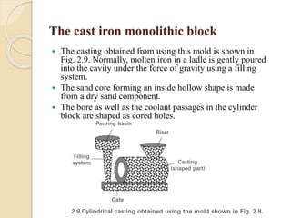
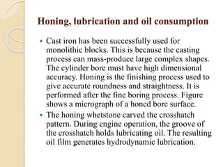
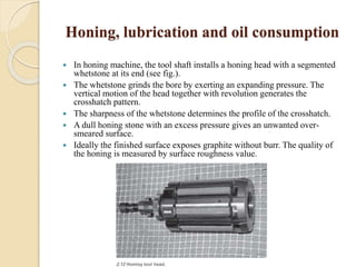
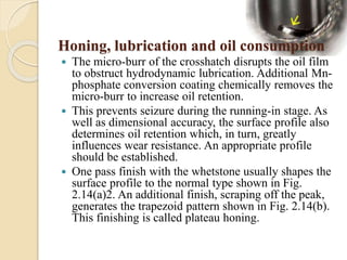
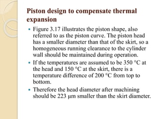
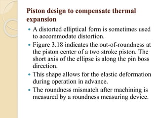
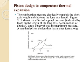
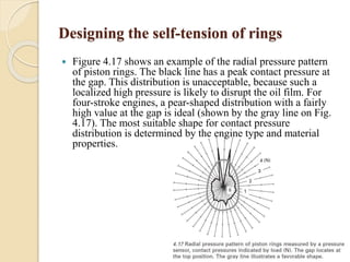
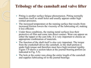
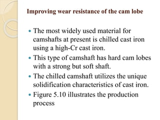
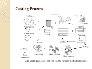
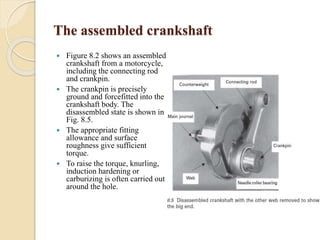
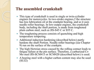
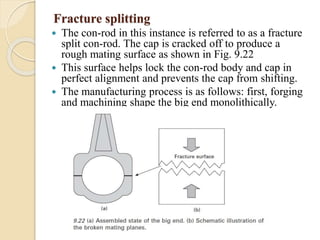
Downloaded 353 times
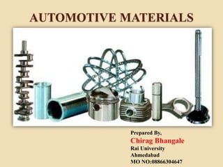

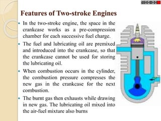
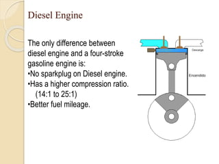
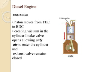
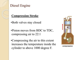
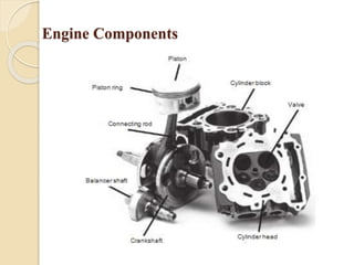
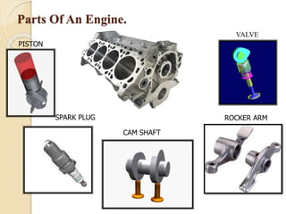
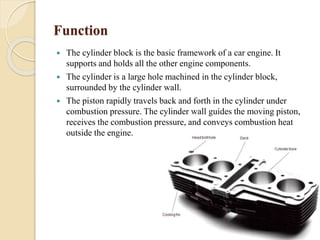
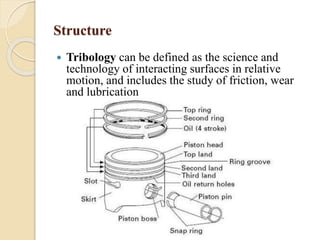
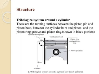
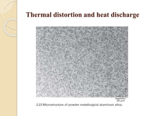
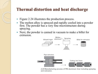


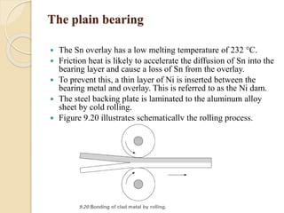


The document provides an overview of automotive materials and the functioning of reciprocating engines, detailing their components, construction, and operation cycles. It discusses both four-stroke and two-stroke engine mechanisms, highlighting the differences between gasoline and diesel engines, including their advantages and disadvantages. Additionally, it covers recent trends in engine technology, different engine parts and materials, and the importance of cylinder structure and cooling systems.


