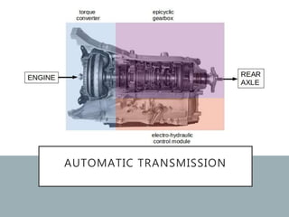
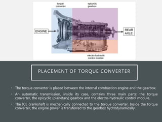
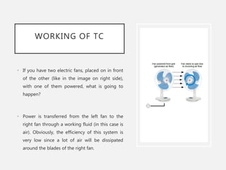
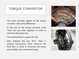
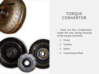
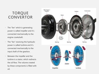
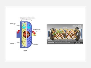
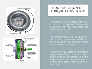
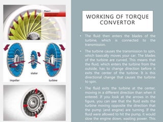
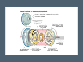
TORQUE CONVERTER
&
AUTOMATIC TRANSMISSION
Prepared & Presented By:
Nitin Kukreja
RELATION BETWEEN
TC & AT
• Most of the modern vehicles are equipped with internal combustion
engines (ICE).
• On a vehicle with manual transmission (MT), the engine engagement &
disengagement can be done in two ways:
• By pressing the clutch pedal
• By selecting Neutral with the gear-shift lever
• On a vehicle with automatic transmission (AT), the engine
disengagement from the transmission is done automatically, without the
intervention of the driver.
• This is possible thanks to the torque converter‘s work principle.
AUTOMATIC TRANSMISSION
PLACEMENT OF TORQUE CONVERTER
• The torque converter is placed between the internal combustion engine and the gearbox.
• An automatic transmission, inside its case, contains three main parts: the torque
converter, the epicyclic (planetary) gearbox and the electro-hydraulic control module.
• The ICE crankshaft is mechanically connected to the torque converter. Inside the torque
converter, the engine power is transferred to the gearbox hydrodynamically.
WORKING OF TC
• If you have two electric fans, placed on in front
of the other (like in the image on right side),
with one of them powered, what is going to
happen?
• Power is transferred from the left fan to the
right fan through a working fluid (in this case is
air). Obviously, the efficiency of this system is
very low since a lot of air will be dissipated
around the blades of the right fan.
TORQUE CONVERTOR
• The same principle applies to the torque
converter, with some differences.
• In the case of the torque converter, both
“fans” are very close together, in order to
minimize the power loss.
• The working fluid is a liquid (AT oil).
• Also, between the two “fans”, there is
another component, which redirects the
fluid flow in order to minimize the losses
and amplifies the transferred torque.
TORQUE
CONVERTOR
• There are four components
inside the very strong housing
of the torque converter:
• 1. Pump
• 2. Turbine
• 3. Stator
• 4. Transmission fluid
TORQUE
CONVERTOR
• The “fan” which is generating
power is called impeller and it’s
connected mechanically to the
engine crankshaft.
• The “fan” receiving the hydraulic
power is called turbine and it’s
connected mechanically to the
input shaft of the gearbox.
• Between the impeller and the
turbine is a stator, which redirects
the oil flow. The volume created
by these components is filled with
oil.
CONSTRUCTION OF
TORQUE CONVERTOR
• The housing of the torque converter
is bolted to the flywheel of the engine,
so it turns at whatever speed the
engine is running at.
• The fins that make up the pump of
the torque converter are attached to
the housing, so they also turn at the
same speed as the engine.
• The pump inside a torque converter is
a type of centrifugal pump. As it spins,
fluid is flung to the outside. As fluid is
flung to the outside, a vacuum is
created that draws more fluid in at
the center.
WORKING OF TORQUE
CONVERTOR
• The fluid then enters the blades of the
turbine, which is connected to the
transmission.
• The turbine causes the transmission to spin,
which basically moves your car. The blades
of the turbine are curved. This means that
the fluid, which enters the turbine from the
outside, has to change direction before it
exits the center of the turbine. It is this
directional change that causes the turbine
to spin.
• The fluid exits the turbine at the center,
moving in a different direction than when it
entered. If you look at the arrows in the
figure, you can see that the fluid exits the
turbine moving opposite the direction that
the pump (and engine) are turning. If the
fluid were allowed to hit the pump, it would
slow the engine down, wasting power. This
WORKING OF
TORQUE
CONVERTOR
• The stator has a very aggressive
blade design that almost
completely reverses the direction of
the fluid.
• A one-way clutch (inside the
stator) connects the stator to a
fixed shaft in the transmission (the
direction that the clutch allows the
stator to spin)
• Because of this arrangement,
you can understand the, Stator can
spin only in the opposite direction,
forcing the fluid to change direction
as it hits the stator blades.
KEY CHARACTERISTICS
• The key characteristic of a torque converter is its
ability to multiply torque when the output rotational
speed is so low.
• This is a feature beyond that of the simple fluid
coupling, which can match rotational speed but does
not multiply torque, thus reduces power.
AUTOMATIC TRANSMISSION
• A hydraulic automatic transmission consists of the following parts:
• Torque Converter which is a type of fluid coupling hydraulically
connecting the engine to the transmission.
• A planetary gearset.
• A set of bands to lock parts of a gearset.
• A set of three wet-plate clutches to lock other parts of the gearset.
• An incredibly odd hydraulic system that controls the clutches and bands.
• A large gear pump to move transmission fluid around.

Torque converter

  • 1.
  • 2.
    RELATION BETWEEN TC &AT • Most of the modern vehicles are equipped with internal combustion engines (ICE). • On a vehicle with manual transmission (MT), the engine engagement & disengagement can be done in two ways: • By pressing the clutch pedal • By selecting Neutral with the gear-shift lever • On a vehicle with automatic transmission (AT), the engine disengagement from the transmission is done automatically, without the intervention of the driver. • This is possible thanks to the torque converter‘s work principle.
  • 3.
  • 4.
    PLACEMENT OF TORQUECONVERTER • The torque converter is placed between the internal combustion engine and the gearbox. • An automatic transmission, inside its case, contains three main parts: the torque converter, the epicyclic (planetary) gearbox and the electro-hydraulic control module. • The ICE crankshaft is mechanically connected to the torque converter. Inside the torque converter, the engine power is transferred to the gearbox hydrodynamically.
  • 5.
    WORKING OF TC •If you have two electric fans, placed on in front of the other (like in the image on right side), with one of them powered, what is going to happen? • Power is transferred from the left fan to the right fan through a working fluid (in this case is air). Obviously, the efficiency of this system is very low since a lot of air will be dissipated around the blades of the right fan.
  • 6.
    TORQUE CONVERTOR • Thesame principle applies to the torque converter, with some differences. • In the case of the torque converter, both “fans” are very close together, in order to minimize the power loss. • The working fluid is a liquid (AT oil). • Also, between the two “fans”, there is another component, which redirects the fluid flow in order to minimize the losses and amplifies the transferred torque.
  • 7.
    TORQUE CONVERTOR • There arefour components inside the very strong housing of the torque converter: • 1. Pump • 2. Turbine • 3. Stator • 4. Transmission fluid
  • 8.
    TORQUE CONVERTOR • The “fan”which is generating power is called impeller and it’s connected mechanically to the engine crankshaft. • The “fan” receiving the hydraulic power is called turbine and it’s connected mechanically to the input shaft of the gearbox. • Between the impeller and the turbine is a stator, which redirects the oil flow. The volume created by these components is filled with oil.
  • 10.
    CONSTRUCTION OF TORQUE CONVERTOR •The housing of the torque converter is bolted to the flywheel of the engine, so it turns at whatever speed the engine is running at. • The fins that make up the pump of the torque converter are attached to the housing, so they also turn at the same speed as the engine. • The pump inside a torque converter is a type of centrifugal pump. As it spins, fluid is flung to the outside. As fluid is flung to the outside, a vacuum is created that draws more fluid in at the center.
  • 11.
    WORKING OF TORQUE CONVERTOR •The fluid then enters the blades of the turbine, which is connected to the transmission. • The turbine causes the transmission to spin, which basically moves your car. The blades of the turbine are curved. This means that the fluid, which enters the turbine from the outside, has to change direction before it exits the center of the turbine. It is this directional change that causes the turbine to spin. • The fluid exits the turbine at the center, moving in a different direction than when it entered. If you look at the arrows in the figure, you can see that the fluid exits the turbine moving opposite the direction that the pump (and engine) are turning. If the fluid were allowed to hit the pump, it would slow the engine down, wasting power. This
  • 12.
    WORKING OF TORQUE CONVERTOR • Thestator has a very aggressive blade design that almost completely reverses the direction of the fluid. • A one-way clutch (inside the stator) connects the stator to a fixed shaft in the transmission (the direction that the clutch allows the stator to spin) • Because of this arrangement, you can understand the, Stator can spin only in the opposite direction, forcing the fluid to change direction as it hits the stator blades.
  • 13.
    KEY CHARACTERISTICS • Thekey characteristic of a torque converter is its ability to multiply torque when the output rotational speed is so low. • This is a feature beyond that of the simple fluid coupling, which can match rotational speed but does not multiply torque, thus reduces power.
  • 15.
    AUTOMATIC TRANSMISSION • Ahydraulic automatic transmission consists of the following parts: • Torque Converter which is a type of fluid coupling hydraulically connecting the engine to the transmission. • A planetary gearset. • A set of bands to lock parts of a gearset. • A set of three wet-plate clutches to lock other parts of the gearset. • An incredibly odd hydraulic system that controls the clutches and bands. • A large gear pump to move transmission fluid around.