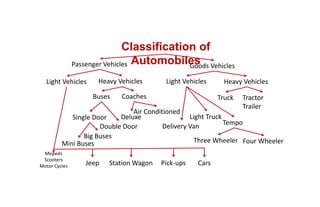
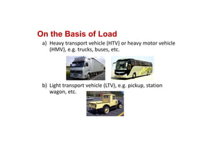
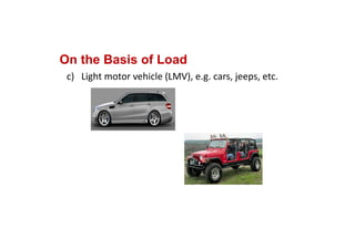
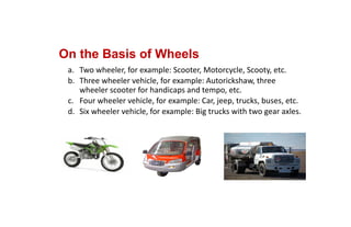
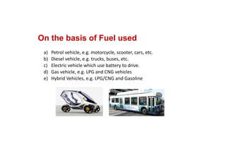
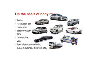
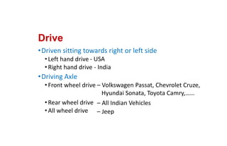
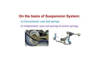
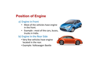
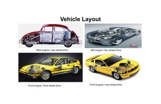
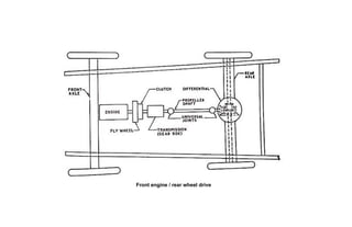
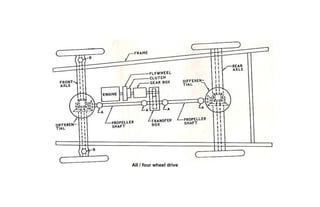
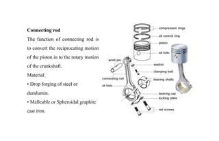
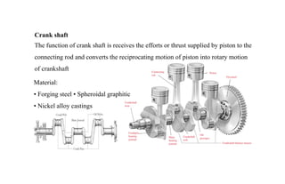
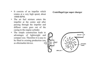
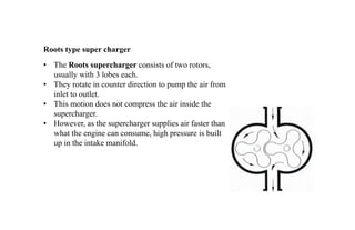
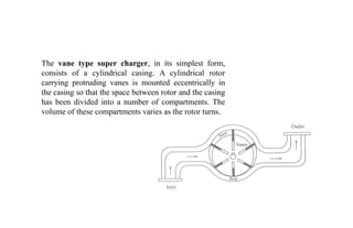
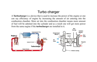
SlideShare a Scribd company logo
1 of 94
Download to read offline
Automobile Engineering
Unit 1
Classification of
Automobiles
Passenger Vehicles Goods Vehicles
Heavy Vehicles
Light Vehicles
Buses Coaches
Deluxe
Air Conditioned
Single Door
Double Door
Mini Buses
Big Buses
Mopeds
Scooters
Motor Cycles Station Wagon
Jeep Pick‐ups Cars
Heavy Vehicles
Light Vehicles
Truck Tractor 
Trailer
Delivery Van
Light Truck
Tempo
Three Wheeler Four Wheeler
On the Basis of Load
a) Heavy transport vehicle (HTV) or heavy motor vehicle 
(HMV), e.g. trucks, buses, etc.
b) Light transport vehicle (LTV), e.g. pickup, station 
wagon, etc.
On the Basis of Load
c)   Light motor vehicle (LMV), e.g. cars, jeeps, etc.
On the Basis of Wheels
a. Two wheeler, for example: Scooter, Motorcycle, Scooty, etc.
b. Three wheeler vehicle, for example: Autorickshaw, three 
wheeler scooter for handicaps and tempo, etc.
c. Four wheeler vehicle, for example: Car, jeep, trucks, buses, etc.
d. Six wheeler vehicle, for example: Big trucks with two gear axles.
On the basis of Fuel used
a) Petrol vehicle, e.g. motorcycle, scooter, cars, etc.
b) Diesel vehicle, e.g. trucks, buses, etc.
c) Electric vehicle which use battery to drive.
d) Gas vehicle, e.g. LPG and CNG vehicles
e) Hybrid Vehicles, e.g. LPG/CNG and Gasoline
On the basis of body style
• Sedan
• Hatchback car.
• Limousine
• Station wagon
• SUV
• Convertible.
• Van
• Special purpose vehicle, 
e.g. ambulance, milk van, etc.
On the basis of Transmission
a) Manual transmission
b) Semi‐automatic
c) Automatic 
Drive
•Driven sitting towards right or left side
•Left hand drive 
•Right hand drive
•Driving Axle
•Front wheel drive 
•Rear wheel drive
•All wheel drive
‐ USA
‐ India
– Volkswagen Passat, Chevrolet Cruze,  
Hyundai Sonata, Toyota Camry,……
– All Indian Vehicles
– Jeep 
a) Conventional: uses leaf springs
b) Independent: uses coil springs & torsion springs.
On the basis of Suspension System:
Position of Engine
a) Engine in Front
• Most of the vehicles have engine 
in the front. 
• Example : most of the cars, buses, 
trucks in India.
b) Engine in the Rear Side
• Very few vehicles have engine 
located in the rear. 
• Example: Volkswagen Beetle
LAYOUT OF AUTOMOBILE & TYPES OF DRIVES OF
AUTOMOBILES
• The main parts of automobile are mounted on the chassis.
• The layout of these components on the chassis are different in different types
of vehicles, i.e., cars, jeeps, trucks, buses, etc.
• The main difference in the layout of this chassis is the position of the engine.
• The engine is located at the front of the vehicle, followed by a clutch, gear box,
propeller shaft, universals joints, differential, rear axle, etc.
• The radiator is located in front of the engine. Various other parts of the
vehicle are dynamo, horn, steering box, fan, timing gear, carburetor, air filter,
gear control, steering wheel, cylinder, petrol tank, rear axle, front axle.
FUNCTIONS OF THE CHASSIS FRAME:
1. To carry load of the passengers or goods carried in the body.
2. To support the load of the body, engine, gear box etc.,
3. To withstand the forces caused due to the sudden braking or
acceleration
4. To withstand the stresses caused due to the bad road condition.
5. To withstand centrifugal force while cornering
TYPES OF CHASSIS FRAMES:
There are three types of frames
• Conventional frame
• Integral frame
• Semi-integral frame
Conventional frame: It has two long side members and 5 to 6 cross members
joined together with the help of rivets and bolts. The frame sections used are
generally.
a. Channel Section - Good resistance to bending
b. Tabular Section - Good resistance to Torsion
c. Box Section - Good resistance to both bending and Torsion
Integral Frame:
• This frame is used now a days in most of the cars.
• There is no frame and all the assembly units are attached to the body.
• All the functions of the frame carried out by the body itself.
• Due to elimination of long frame it is cheaper and due to less weight most
economical also.
• Only disadvantage is repairing is difficult.
Semi - Integral Frame:
In some vehicles half frame is fixed in the front end on which engine gear box and
front suspension is mounted. It has the advantage when the vehicle is met with
accident the front frame can be taken easily to replace the damaged chassis frame.
This type of frame is used in FIAT cars and some of the European and American
cars.
VARIOUS LOADS ACTING ON THE FRAME:
 Short duration Load - While crossing a broken patch.
 Momentary duration Load - While taking a curve.
 Impact Loads - Due to the collision of the vehicle.
 Inertia Load - While applying brakes.
 Static Loads - Loads due to chassis parts.
 Over Loads - Beyond Design capacity.
The Automobile bodies are divided
in two groups
1. Passenger body
2. Commercial body
REQUIREMENTS OF BODIES FOR VARIOUS TYPES OF VECHILE:
1. The body should be light.
2. It should have minimum number of components.
3. It should provide sufficient space for passengers and luggage.
4. It should withstand vibrations while in motion.
5. It should offer minimum resistance to air.
6. It should be cheap and easy in manufacturing.
7. It should be attractive in shape and colour.
8. It should have uniformly distributed load.
9. It should have long fatigue life
10.It should provide good vision and ventilation.
Vehicle Layout
Rear engine / rear wheel drive Mid engine / four wheel drive
Front engine / front wheel drive Front engine / rear wheel drive
Front engine / rear wheel drive
All / four wheel drive
Front Engine - Rear Wheel Drive
This layout is one of the oldest layout which remained unchanged for many years.
some of the advantages provided by this system are :
(a) Balanced weight distribution between the front and the rear wheels.
(b) Easy front wheel steering.
(c) Behind the rear seats, large luggage space is available.
(d) Accessibility to various components like engine, gearbox and rear axle is better
in comparison to other layouts. The control linkages-accelerator, choke, clutch and
gearbox are short and simple.
(e) Full benefits of the natural air stream created by vehicle’s movement is taken by
the forward radiator resulting in reduced power losses from a large fan.
Rear Engine-Rear Wheel Drive
• This arrangement eliminates the necessity for a propeller shaft when the engine
is mounted adjacent to the driven wheels.
• The engine-clutch-gear box-final drive form a single unit in this layout..
• Compared to FWD it has a simpler drive shaft layout. Further, the weight of rear
engine on the driving wheels provides excellent traction and grip.
• very effective rear wheel braking is possible.
• Due to the absence of the propeller shaft the obstructed floor space is reduced.
The front of the vehicle can, therefore, be designed for good visibility and
smooth air flow.
• Natural air cooling is not possible, it requires a powerful fan.
• Long linkage required for the engine, clutch and the gear box controls.
• The rearward concentration of weight causes the vehicle to be more affected by
side winds at high speeds. this makes the vehicle unstable resulting in over
steering and turning very sharply into a curve.
Front Engine-Front Wheel Drive
• This layout provides optimum body-luggage space and a flat floor
• Provides good grip and good road holding on curves due to major weight at the
front and chance of skidding on slippery surface is very much reduced.
• when the vehicle is to be ‘steered in’ to the curve, it provides ‘understeer’
characteristics always preferred by drivers.
• This requires special universal joints and a more complicated assembly.
Four Wheel Drive/ All Wheel Drive
• Offer Excellent traction - both on dry pavement and in poor weather
• Offer double the traction that is offered by 2WD systems
• More weight and cost
• Requires special service and maintenance
• Braking distance is more because of more weight
Types of engines: Mainly engines are of two types.
External Combustion Engines: The External Combustion Engines are those in
which the combustion takes place outside the engine cylinder. E.g.: Steam Engine.
Internal Combustion Engines: In the Internal Combustion Engines the combustion
of fuel takes place inside the engine cylinder. E.g.: All Automobile Engines.
Functions of I.C. Engine: Engine is that kind of prime mover which converts
chemical energy of fuel into mechanical energy. The fuel on burning changes to
gas which impinges upon the piston and pushes it to change into reciprocating
motion. The reciprocating motion of piston is then converted to rotary motion of
crank shaft with the help of slider mechanism involving connecting rod and crank
shaft.
Classifications of I.C. Engines
The I.C. Engine can be classified on the basis of
1. Working cycle:
a. Otto cycle Engine or Spark Ignition Engine (S.I. Engine)
b. Diesel Cycle Engine or Compression Ignition engine (C.I. Engine)
2. Number of strokes:
a. Two Stroke engine, b. Four Stroke engine.
3. Fuel used:
a. Liquefied petrol engines, b. Diesel engines, c. Gasoline or petrol,
b. d. Compressed Natural gas engines, e. Methane or ethanol engines.
4. Fuel supply system:
a. Fuel supply through carburetor, b. Fuel injected by Fuel injecting pump.
5. Method of ignition:
a. battery or coil ignition, b. Magneto ignition, c. Electronic ignition
6. Method of cooling:
i) Air cooled, ii) Water cooled
7. Cylinder Arrangement:
i) in line type, ii)V type, iii) Opposed cylinder type, iv)Radial type
8. Valve operating system:
i) Overhead, ii) Side valve type
Materials used, function and Constructional details of Petrol Engine
Components
Engine consists of the following parts.
1. Cylinder block
2. Cylinder head
3. Crankcase
4. Piston
5. Piston Rings
6. Piston Pin
7. Connecting Rod
8. Crankshaft
9. Flywheel
10. Valves and valve mechanism
11. Rocker Arm
12. Camshaft
besides the these components engine contain so many
accessories like air cleaner, oil filter, automatic chokes,
automatic heat controls, spark plug, ignition devices,
carburetors, manifolds, vibration damper etc.
Cylinder block
The main function of cylinder is to guide the piston.
Material :
Grey cast iron or Aluminium alloy
oCylinder
oCylinder liners
oDry liner
oWet liner
Cylinder head
The main function of cylinder head is to seal the cylinder block and not to permit
entry and exit of gases on cover head valve engine.
Material :
Grey cast iron or Aluminium alloy
Pistons
Functions:
• To transmit the force of explosion to the crankshaft.
• To form a seal so that the high pressure gases in the combustion chamber do not
escape in to the crankcase.
• To serve as guide and a bearing for small end of the connecting rod.
Material:
• Cast iron and aluminium alloy (Aluminium – silicon)
Piston rings
Functions:
• Prevention of leakage of gas into the crank case.
• Prevention of lubricating oil film
• Prevention of lubricant entry into the combustion chamber above the piston head.
• Removing unnecessary and excessive lubricating oil from cylinder wall.
• Prevention of carbon deposit and other impurities.
• Easy transmission of heat from piston to cylinder wall.
• Balancing of side thrust of the piston
Piston rings are made of cast iron of fine grain and high elastic material which is
not affected by the working heat. Sometimes it is made by alloy spring steel.
Connecting rod
The function of connecting rod is
to convert the reciprocating motion
of the piston in to the rotary motion
of the crankshaft.
Material:
• Drop forging of steel or
duralumin.
• Malleable or Spheroidal graphite
cast iron.
Crank shaft
The function of crank shaft is receives the efforts or thrust supplied by piston to the
connecting rod and converts the reciprocating motion of piston into rotary motion
of crankshaft
Material:
• Forging steel • Spheroidal graphitic
• Nickel alloy castings
Crankcase (or) Oil sump (or) Oil pan
The main body of the engine to which the cylinder are attached and which
contains the crankshaft and crankshaft bearing is called crankcase.
Function:
• To store the oil for the engine lubricating system.
• To collect the return oil draining from the main bearings or from the cylinder
walls.
• To serve as a container in which any impurities or foreign matter.
• To provide for cooling of the hot oil in the sump by transfer of heat to the
outside air stream.
Material:
• Pressed steel sheet or Aluminium alloy
Turbo charging and Super charging
Super Charger
• A supercharger is a device which increases the pressure of the air fuel mixture
from the carburetor before it enters the engine.
• It is connected between the carburetor and the cylinder in the way of intake
manifold.
• It is usually driven by the engine through suitable gears and shafts.
• There are 3 types of superchargers.
1. Centrifugal type
2. Vane type
3. Roots air blower type.
• It consists of an impeller which
rotates at a very high speed, about
10000 RPM.
• The air fuel mixture enters the
impeller at the centre and after
passing through the impeller and
diffuser vanes goes out of the
casing to the engine cylinder.
• The simple construction leads to
advantages of lightweight and
compact size. Therefore it is easy to
be fitted to existing production cars
as aftermarket device.
Centrifugal type super charger
• The Roots supercharger consists of two rotors,
usually with 3 lobes each.
• They rotate in counter direction to pump the air from
inlet to outlet.
• This motion does not compress the air inside the
supercharger.
• However, as the supercharger supplies air faster than
what the engine can consume, high pressure is built
up in the intake manifold.
Roots type super charger
The vane type super charger, in its simplest form,
consists of a cylindrical casing. A cylindrical rotor
carrying protruding vanes is mounted eccentrically in
the casing so that the space between rotor and the casing
has been divided into a number of compartments. The
volume of these compartments varies as the rotor turns.
Comparison between the three Superchargers
• The required characteristics of centrifugal type has limitations & are suitable
for only low speeds
• The root’s type is simple in construction, minimum maintenance and longer
life
• The vane type has problem of wear of the tips of vanes over a period of time
Depending upon the application, the type of supercharger should be decided
Turbo charger
A Turbocharger is a device that is used to increase the power of the engine or one
can say efficiency of engine by increasing the amount of air entering into the
combustion chamber. More air into the combustion chamber means more amount
of fuel will be admited into the cylinder and as a result one will get more power
from the same engine if the turbocharger are installed in it.
• A turbocharger mainly consists of two main sections: the turbine and the
compressor.
• The turbine consists of turbine wheel and the turbine housing whose purpose is to
guide the exhaust gases into the turbine wheel.
• The kinetic energy of the exhaust gases gets converted into the mechanical
energy after striking the turbine blades.
• The exhaust outlet helps the exhaust gases to exit from the turbine.
• The compressor wheel in turbocharger is attached to a turbine with the help of
steel shaft.
• As the turbine turns the compressor wheel, it draws the high-velocity, low
pressure air stream and convert it into high-pressure, low –velocity air stream.
• This compressed air is pushed into the engine with the more quantity of fuel and
hence produce more power.
TURBOCHARGER Vs SUPERCHARGER.
The function of the supercharger is same as that of turbocharger but the
supercharger is driven mechanically by the engine, often with the help of belt
connected to the crankshaft, whereas turbocharger is powered by a turbine
driven by the engine’s exhaust gases. Turbocharger is considered more
efficient than the superchargers as they are using the wasted energy of exhaust
gases for its power source.
Engine lubrication
Objects of lubrication
1. To reduce friction between the moving parts.
2. To reduce wear of the moving parts.
3. To act as cooling medium for removing heat.
4. To keep the engine parts clean, especially piston rings and ring grooves, Oil
ways and filters.
5. To absorb shock between bearings and other engine parts thus reducing engine
noises and extending engine life.
6. To form a good seal between piston rings and cylinder walls.
Types of lubricants
• Solid (graphite, mica , soap stone)
• Semi-solid (grease)
• Liquid
• Petroleum Based
• Refined from crude oil
• Supplemented with additives
• Synthetic
• Lubricants chemically engineered from pure chemicals rather than refined
from crude oil.
• More expensive but can provide significant advantages over refined oils.
• Longer oil change intervals
• Longer engine life
• Increase gas mileage
Properties of lubricants
• An engine lubricating oil must have certain properties or characteristics for it
satisfactory function as follows.
1. Viscosity
2. Flash point
3. Fire point
4. Cloud point
5. Pour point
6. Oiliness
7. Corrosion
8. Chemical stability
9. Sulphur content
• Viscosity: It is a measure of the resistance to flow or the internal friction of an
oil. Viscosity is one of the most important properties of engine lubricating oil.
Flash Point: The flash point is defined as lowest temperature at which the
lubricating oil will flash when a small flame is passed across its surface.
• Fire Point: If the oil is heated further after the flash point has been reached, the
lowest temperature at which the oil will burn continuously is called the fire point.
• Cloud Point: The oil changes from liquid state to a plastic or solid state when
subjected to low temperatures. In some cases the oil starts solidifying which
makes it to appear cloudy. The temperature at which this takes place is called the
cloud point.
Pour Point: It is the lowest temperature at which the lubricating oil will pour. The
pour point of an oil is lubrication of its ability to move at low temperatures. This
property must be considered because of its effort on starting an engine in cold
weather and on free circulation of oil through exterior feed pipes when pressure is
not applied.
Oiliness: It is the characteristic property of the oil when it has oiliness. This
property is highly desirable in helping the lubricant to adhere to the cylinder walls.
Corrosion: The corrosion has been defined as the destruction of a solid body by
chemical or electrochemical action which starts intentionally from its outer
surface. A lubricant should not corrode the working parts and it must retain its
properties even in the presence of foreign matter and additives.
Chemical stability: The lubricating oil should also be chemically stable, there
should not be any tendency for oxide formation. The oxidation clog the working
parts, cause the faulty piston rings and valve action. The oil should also not
decompose at high temperatures to form carbon which makes spark plug and valves
faulty to function.
Sulphur content: If sulphur is present in considerable amount in the lubricating oil
it promotes corrosion. The corrosion test shows the amount of sulphur content.
Oil additives
• Viscosity index improvers
• used to enhance the base qualities of the oil, and to keep the oil from thinning
too much as heat increases.
• Pour-point depressants
• prevent crystals from forming in extreme cold conditions, and consequently
lower the oil's pour point (temperature at which it pours).
• Oxidation inhibitors
• help prevent the oil from oxidizing (in other words, burning). When oil
oxidizes, it loses its ability to protect the engine. It also produces sludge
deposits and traps corrosive acids.
• Rust-corrosion inhibitors
• help prevent and neutralize water and oxygen from acid-etching the metals in
the engine and forming rust particles. If this corrosion were to happen, some
complex acids would form and other sludge problems would occur.
• Dispersants
• help the oil to absorb and retain contaminants such as dirt or tiny metal
particles (from engine wear) until the oil passes through the oil filter, where
the contaminants are trapped.
• Detergents
• help to remove contaminants from the engine components and hold them in
the oil until it reaches a filter, or until it is changed the next time.
• Friction modifiers/wear inhibitors
• "stick" to engine surfaces better, reducing friction and improving fuel
economy. Oils with the "energy conserving" labels contain friction modifiers.
• Foam inhibitors (Antifoamants)
• prevent the oil from being whipped into many tiny air bubbles. Air bubbles
don't lubricate. This also helps prevent sludge formation when the emulsion
process is a possible threat in an engine.
The various types of lubrication systems adopted in automobiles are
1. Petroil/Mist lubricating system
2. Autolube System
3. Splash lubricating system
4. Forced feed lubricating system
5. Dry sump lubricating system
6. Wet sump lubricating system
Petroil/Mist lubricating system:
• It is the simplest form of lubricating system. It does not consist of any separate
part like oil pump for the purpose of lubrication.
• This system of lubrication is generally adopted in two stroke petrol engines like
scooters, mopeds and motor cycles.
• The lubricating oil is mixed into the petrol itself while filling in the petrol tank
of the vehicle, in a specified ratio.
• When the fuel goes into the crank chamber during the engine operation, the oil
particles go deep into the bearing surfaces and lubricate them.
• The piston rings, cylinder walls, piston pin etc. are lubricated in the same way.
Autolube System
• Used in 2 stroke engines
• Oil is stored in a separate tank
• A nozzle sprays measured quantity of oil in the crankcase in every stroke
• More efficient than mist lubrication system
• Used in Kinetic Honda, Yamaha RX 100
Splash Lubrication system:
• In this system of lubrication, the lubricating oil is stored in an oil trough or sump.
A scoop or dipper is made in the lowest part of connecting rod.
• When the engine runs, the dipper dips in the oil once in every revolution of the
crankshaft and causes the oil to splash in the cylinder walls.
• This action effects the lubrication of the engine walls, piston rings, crankshaft
bearings and big end bearings.
• Splash system mostly works in connection with the pressure system in an engine,
some parts being lubricated by splash system and other by pressure system.
Splash Lubrication system
Pressure lubrication system:
• In this system of lubrication, the engine parts are lubricated under pressure feed.
• The lubricating oil is stored in a separate tank on the sump, from where an oil
pump takes the oil through a strainer and delivers it through a filter to the main oil
gallery at a pressure of 2-4 kg/cm2.
• The oil from the main gallery, goes to the main bearings, falls back to the sump,
some is splashed to lubricate the cylinder walls and the remaining goes through a
hole to the crankpin.
• From the crankpin it goes into the piston pin through a hole in the connecting rod
web, where it lubricates the piston rings.
• For lubricating camshaft and timing gears, the oil is led through a separate oil line
from the oil gallery.
• The valve tappets are lubricated by connecting the main oil gallery to the tappet
guide surfaces through drilled holes.
• An oil pressure gauge at the instrument panel indicates the oil pressure in the
system clear off the oil from dust metal particles and other harmful particles.
Pressure lubrication system
Dry sump lubrication system
• The system in which the lubricating oil is stored in the oil sump is called wet sump
system, like the pressure system. But the system in which the lubricating oil is not
kept in the oil sump is known as dry sump system. In this system the oil is stored
in a separate tank from where it is fed to the engine.
• The oil which falls into the oil sump after lubrication is sent back to the oil tank by
a separate delivery pump.
• The system uses two pumps, one to feed the oil and the other to deliver it back to
the oil tank. This system is used in situation where the vehicle has to change its
position continuously, like in air crafts. The main advantage of this system is that
there is no chance of break in oil supply during vehicle up and down movement.
Parts of Lubricating System:
1. Oil sump or tank
2. Oil pump
3. Oil cooler
4. Oil filter and strainer
5. Oil pressure gauge
6. Oil level indicator
7. Oil pressure indicating light
Types of Oil Pumps
There are two basic types of oil pumps:
• Twin gear pumps are mounted inside the
oil pan on the bottom of the engine and use
a pair of intermeshing gears to pump oil.
• One gear is driven by a shaft and the
second gear is driven by the first gear. The
pump is usually driven by a shaft that
connects to the crankshaft, camshaft or
distributor shaft. Thus, the pump operates
at half engine rpm.
• The pump gears turn in opposite directions.
This traps oil between the gear teeth and
carries it around the outside of each gear
from the pickup tube inlet to the pump
outlet.
• The tight clearances between the
gears prevents the oil from
flowing backwards to the inlet.
• Rotor pumps have an inner gear that turns inside an
outer rotor.
• The inner gear has one less lobe than the outer rotor.
The inner gear is also mounted slightly offcenter to the
outer rotor which forces the outer rotor to spin at about
80% of the speed of the inner gear.
• This creates a bellows-like pumping action that pulls oil
from the inlet port and pushes it towards the outlet port.
Close tolerances are required for good
pumping efficiency.
• This type of pump may also be located in the crankcase.
Oil filters
• Micro-porous paper filters used to screen out particles.
• Most filters are of the cartridge type.
• Remove harmful materials
• Two Types
oFull Flow
oBypass
Cartridge type oil filter
• The Cartridge type consists of a filtering
element placed in a metallic casing. The casing
has inlet and outlet oil pump enters casing
through the filtering element, which takes up
all the impurities.
• The filtered oil then comes out from the casing
and goes to the oil gallery.
• The filtering element may be cleared when
clogged.
Edge type filter
• The Edge type filtering element consists of a number
of discs in a casing through which the oil passes.
• The alternate discs are mounted over a spindle and,
between these discs another set of discs are fixed to a
separate square rod.
• The clearance between the discs is only a few
thousand of centimeter.
• When the oil flows through this small clearance, it
leaves impurities on the disc peripherals.
• The Centrifugal type consists of a stationary
casing, rotor casing, central spindle and tubes
with jets.
• The important oil enters the hollow central
spindle and through holes around its
periphery, the oil goes to the rotor casing.
• From the rotor casing the oil goes in the
tubes, at the ends of which jets under
pressure, the reaction of which gives the
motion to the rotor casing so that it starts
rotating.
• The oil from the jets impinges on the walls of
the stationary casing under heavy pressure,
where the impurities are retained and the
clean oil falls below which is taken for use.
The filter walls are cleared periodically.
• In full flow system, the whole oil passes first
through the filters and then goes to the
bearings.
• If the filter is clogged due to any reason, the
system fails completely and bearings would be
starved.
• A coarse filter is used
• Relief valve is used to ensure oil supply to
engine in case of filter clogging
Full flow filtering system
• In Bypass filter system, the whole of the oil does
not pass through the filter
• Part of oil goes from sump to filter
• Part goes to engine for lubrication
• When the engine is running continuously for a
long period, entire oil is filtered
• Very fine filter is used
Bypass filtering system
CRANK CASE VENTILATION
• The products of combustion contain mainly nitrogen, water and carbon dioxide,
sulphuric acid (due to sulphur content in the fuel)
• It is quite possible that the product of combustion may leak through the piston
rings into the crankcase oil by slipping past the piston rings.
• Thus the lubricating oil in the crankcase becomes dilute when mixed with water
and gasoline which leak past the piston rings. The acid causes corrosion of the
crankcase metals as water does.
• If either or both are allowed to enter and remain in the crankcase, the crankcase
ventilation removes all these unwanted particles from the crankcase, which leak
past the piston rings.
• It prevents the lubricating oil from becoming dilute and corrosion of crankcase
metals due to acid formation.
• Road draught crankcase ventilation system
• Induction manifold positive crank case ventilation system
• In a positive crankcase ventilation, the
crankcase vapor are returned to the engine
through the intake manifold, instead of
being exhausted into the atmosphere.
• The crankcase outlet tube is connected to
the manifold just beneath the carburetor.
• So that the vapors are drawn into the intake
manifold and utilized into the cylinder
during the operation.
SERVICING OF ENGINE
• Engine servicing is a method of engine reconditioning. In this method the old and
worn engines are dismantled completely, repair and reassemble all the parts,
Rebuild the engine, rebore the cylinders etc., and refit the engine.
• For Servicing of an Engine, the following points are to be attended.
1. Cleaning the Engine, Reconditioning of Engine by Valve Servicing, Cylinder
reboring, Crankshaft turning etc.
2. Servicing of Cooling System
3. Servicing of Lubrication System
4. Servicing of Fuel Supply System etc
Servicing of Engine includes valve Refacing, valve grinding
Crank shaft Turning are to be attended.
• Degreasing /cleaning
• A layer of oil, grease and dirt gets coated to the engine parts with passage of time
and usage. The unwanted layer of grease dist etc., should be removed.
• This can be done by hand cleaning or by means of certain cleaning methods.
• For degreasing of smaller parts, the parts are being brushed or scrubbed with a
stiff bristle brush to get rid of hard deposits.
• Other dirty parts are placed in a large perforated tray or wire basket and exposed
within a tank to the vapour of the heated Trichloroethylene.
• Decarbonization
• Carbon is deposited in the cylinder due to rich mixture supply, use of wrong grade
oil, unnecessary idling, too much oil, poor fitted piston and piston rings.
• Deposition of carbon causes Engine knockings, missing of explosion and burnt
value resulting in loss of power.
• These are in general three methods of decarbonizing or decoking.
1) Scrapping method
2) Oxygen decarbonizing method
3) Chemical method of decarbonizing
Scrapping method :
• The scrapping of the carbon is done by hand scrapping with the help of tools.
• To remove the carbon quickly, carbon removing brushes may be fixed in the
chuck of an electric portable drill.
• To clean valve grinder, valve stems etc., special wire brushes may also be used.
Oxygen De-carbonizing method:
• It is the process of removing carbon from the inside of the cylinder and head of
the piston without removing cylinder head by means of an oxygen flame.
• The equipment consists of an oxygen tank fitted at an initial pressure of 156
kg/cm² and an adjustable reducing valve for bringing the pressure down to 0.7 to
1.4 kg/cm².
• The oxygen is applied to the combustion space by inserting a flexible delivery jet
through a valve by slightly bending it.
• The oxygen flame will burn away all the carbon deposits completely.
Chemical Method of De-carbonizing:
• A special chemical is injected into the spark plug or injector hole in liquid form.
The engine should be in warm condition so that the liquid can act more efficiently.
• After twelve hours the carbon in loosened, so that upon starting the engine it is
blown out of the exhaust pipe.
RECONDITIONING OF CYLINDER:
• After prolonged usage of the engine, the cylinder of the engine will get maximum
taper wear and ovality wear.
• The Taper and Ovality wear will occur only after 40000 to 60000 kms run.
• Generally the maximum permissible ovality is specified as 0.01 mm and taper as
0.25 mm.
• Cylinder bores with less than 0.01 mm Ovality need not be rebored. They should
only be Honed.
CYLINDER REBORING:
• Reboring is done by the reboring machine in which a single point cutter which
is set to exact diameter required with special micrometer.
• The cutter blade shaft is mounted inside a column which moves up and down its
housing in the fixed part of the machine for tool feeding purpose.
• The top surface of the cylinder block is thoroughly cleaned and the boring bar
set at one of the cylinder bores.
• After completing boring the cylinder must be washed thoroughly to remove all
abrasive particles.
CYLINDER REBORING
MACHINE
CYLINDER HONING METHOD:
• After Reboring, Honing is required to finish the bore to smooth finish.
• It removes minor imperfections and glaze. A hone consists of four or six narrow,
narrow graded grinding stones mounted in cage around a spindle which rotated
by an electric motor.
• Place the Hone in the cylinder and expand the stones until the assembly can just
be turned by hand and machine started.
• Move the Hone up and down slowly with the first cut rough Hone up and down
slowly with the first cut rough stones, but more rapidly with the finish cut five
stones.
Honing
Nitriding of crank shaft
• It is a surface modification processes developed industrially to improve the wear,
corrosion and fatigue resistance of a steel.
• Machine components such as crankshaft are subjected to alternating stresses
and thus there is a requirement of good toughness but very hard and wear
resistant surface.
• To achieve this a process known as Nitriding is performed in which Nitrogen
content is increased on the surface and hard nitrides are formed
• The component is exposed to nitrogenous atmosphere or dipped into Nitriding
salt bath
• Some notable characteristics of the process are
• No quenching is required
• The component is needed to be heat treated before Nitriding is performed

More Related Content

What's hot

AUTOMONBILE CHASSIS & BODY ENGINEERING
AUTOMONBILE CHASSIS & BODY  ENGINEERING AUTOMONBILE CHASSIS & BODY  ENGINEERING
AUTOMONBILE CHASSIS & BODY ENGINEERING Devendra Hembade
 
Vehicle Structure and Engines
Vehicle Structure and EnginesVehicle Structure and Engines
Vehicle Structure and EnginesPraveenManickam2
 
Dual clutch transmission system ppt presentation
Dual clutch transmission system ppt presentationDual clutch transmission system ppt presentation
Dual clutch transmission system ppt presentationAlok Prakash Singh
 
Manual transmission system in automobiles
Manual transmission system in automobilesManual transmission system in automobiles
Manual transmission system in automobileschaudhryshailja
 
Powertrain Configuration Designs
Powertrain Configuration DesignsPowertrain Configuration Designs
Powertrain Configuration DesignsSteve Spilman
 
Automobile chassis,types of automobile
Automobile chassis,types of automobileAutomobile chassis,types of automobile
Automobile chassis,types of automobilekgmahesh123
 
Construction of conventional, semi integral & integral type vehicles
Construction of conventional, semi integral & integral type vehiclesConstruction of conventional, semi integral & integral type vehicles
Construction of conventional, semi integral & integral type vehiclesKowshigan S V
 
Automobile chassis frame
Automobile chassis frameAutomobile chassis frame
Automobile chassis framejjHF47
 
Different types of suspension system
Different types of suspension systemDifferent types of suspension system
Different types of suspension systemHOME
 
automobile workshop ppt Traning report by c rang rajan and sudhir kumar
automobile workshop ppt Traning report by c rang rajan and sudhir kumarautomobile workshop ppt Traning report by c rang rajan and sudhir kumar
automobile workshop ppt Traning report by c rang rajan and sudhir kumarchakrawarti rang rajan
 
Hydraulic steering
Hydraulic steeringHydraulic steering
Hydraulic steeringAzeem Waqar
 
Automatic transmission
Automatic transmissionAutomatic transmission
Automatic transmissionsaffrony09
 

What's hot (20)

Frame and body of Automobile
Frame and body of AutomobileFrame and body of Automobile
Frame and body of Automobile
 
AUTOMONBILE CHASSIS & BODY ENGINEERING
AUTOMONBILE CHASSIS & BODY  ENGINEERING AUTOMONBILE CHASSIS & BODY  ENGINEERING
AUTOMONBILE CHASSIS & BODY ENGINEERING
 
6 power steering
6 power steering6 power steering
6 power steering
 
8 exhaust brake
8 exhaust brake8 exhaust brake
8 exhaust brake
 
2.chassis types
2.chassis types2.chassis types
2.chassis types
 
Braking system
Braking systemBraking system
Braking system
 
Vehicle Structure and Engines
Vehicle Structure and EnginesVehicle Structure and Engines
Vehicle Structure and Engines
 
Dual clutch transmission system ppt presentation
Dual clutch transmission system ppt presentationDual clutch transmission system ppt presentation
Dual clutch transmission system ppt presentation
 
Manual transmission system in automobiles
Manual transmission system in automobilesManual transmission system in automobiles
Manual transmission system in automobiles
 
Automobile Basics
Automobile BasicsAutomobile Basics
Automobile Basics
 
Powertrain Configuration Designs
Powertrain Configuration DesignsPowertrain Configuration Designs
Powertrain Configuration Designs
 
Automobile chassis,types of automobile
Automobile chassis,types of automobileAutomobile chassis,types of automobile
Automobile chassis,types of automobile
 
Automatic transmission system ppt
Automatic transmission system pptAutomatic transmission system ppt
Automatic transmission system ppt
 
Construction of conventional, semi integral & integral type vehicles
Construction of conventional, semi integral & integral type vehiclesConstruction of conventional, semi integral & integral type vehicles
Construction of conventional, semi integral & integral type vehicles
 
Automobile chassis frame
Automobile chassis frameAutomobile chassis frame
Automobile chassis frame
 
Different types of suspension system
Different types of suspension systemDifferent types of suspension system
Different types of suspension system
 
automobile workshop ppt Traning report by c rang rajan and sudhir kumar
automobile workshop ppt Traning report by c rang rajan and sudhir kumarautomobile workshop ppt Traning report by c rang rajan and sudhir kumar
automobile workshop ppt Traning report by c rang rajan and sudhir kumar
 
Hydraulic steering
Hydraulic steeringHydraulic steering
Hydraulic steering
 
Automatic transmission
Automatic transmissionAutomatic transmission
Automatic transmission
 
Alignment for car
Alignment for carAlignment for car
Alignment for car
 

Similar to Automobile engineering unit 1

Automobile Engineering.ppt
Automobile Engineering.pptAutomobile Engineering.ppt
Automobile Engineering.pptsivasankar480633
 
Introduction to automotive system
Introduction to automotive system Introduction to automotive system
Introduction to automotive system CrazyBeats1
 
Unit 1 - Automobile Engineering - Intro.pdf
Unit 1 - Automobile Engineering - Intro.pdfUnit 1 - Automobile Engineering - Intro.pdf
Unit 1 - Automobile Engineering - Intro.pdfbharathvarshsrinivas
 
M.tech 1st sem automobile that useful for development
M.tech 1st sem automobile that useful for developmentM.tech 1st sem automobile that useful for development
M.tech 1st sem automobile that useful for developmentBinayaBhusanPanda
 
Automobile Engineering.pptx
Automobile Engineering.pptxAutomobile Engineering.pptx
Automobile Engineering.pptxGovind Samleti
 
1.1 Classification of automobile.pdf
1.1 Classification of automobile.pdf1.1 Classification of automobile.pdf
1.1 Classification of automobile.pdfPartap Samra
 
Vehicle Body Engineering - Introduction
Vehicle Body Engineering - IntroductionVehicle Body Engineering - Introduction
Vehicle Body Engineering - IntroductionRajat Seth
 
UME1603AUTOU1L1 - Introduction Chassis.pptx
UME1603AUTOU1L1 - Introduction  Chassis.pptxUME1603AUTOU1L1 - Introduction  Chassis.pptx
UME1603AUTOU1L1 - Introduction Chassis.pptxDhanushNatesan
 
Defining Automotive Technology by SouLSteer
Defining Automotive Technology by SouLSteerDefining Automotive Technology by SouLSteer
Defining Automotive Technology by SouLSteerShobhit Gosain
 
1.vbe intro compatibility-mode_
1.vbe intro compatibility-mode_1.vbe intro compatibility-mode_
1.vbe intro compatibility-mode_navinrawat27
 
unit1 new.pptx
unit1 new.pptxunit1 new.pptx
unit1 new.pptxserinaraj
 
Auto class notes
Auto class notesAuto class notes
Auto class notesJohn Alexis
 
AUTOMOBILE ENGINEERING.pptx
AUTOMOBILE ENGINEERING.pptxAUTOMOBILE ENGINEERING.pptx
AUTOMOBILE ENGINEERING.pptxMohammadKhalid89
 
Automobile - Frame, Chassis and Drives
Automobile - Frame, Chassis and DrivesAutomobile - Frame, Chassis and Drives
Automobile - Frame, Chassis and DrivesRavi Thakor
 
automobile engineering
automobile engineeringautomobile engineering
automobile engineeringSaurabh Negi
 
1. Introduction to Automobile.ppt
1. Introduction to Automobile.ppt1. Introduction to Automobile.ppt
1. Introduction to Automobile.pptAtharvaJagtap15
 

Similar to Automobile engineering unit 1 (20)

Automobile Engineering.ppt
Automobile Engineering.pptAutomobile Engineering.ppt
Automobile Engineering.ppt
 
Introduction to automotive system
Introduction to automotive system Introduction to automotive system
Introduction to automotive system
 
Unit 1 - Automobile Engineering - Intro.pdf
Unit 1 - Automobile Engineering - Intro.pdfUnit 1 - Automobile Engineering - Intro.pdf
Unit 1 - Automobile Engineering - Intro.pdf
 
M.tech 1st sem automobile that useful for development
M.tech 1st sem automobile that useful for developmentM.tech 1st sem automobile that useful for development
M.tech 1st sem automobile that useful for development
 
Unit- I.pptx
Unit- I.pptxUnit- I.pptx
Unit- I.pptx
 
Automobile Engineering.pptx
Automobile Engineering.pptxAutomobile Engineering.pptx
Automobile Engineering.pptx
 
1.1 Classification of automobile.pdf
1.1 Classification of automobile.pdf1.1 Classification of automobile.pdf
1.1 Classification of automobile.pdf
 
Vehicle Body Engineering - Introduction
Vehicle Body Engineering - IntroductionVehicle Body Engineering - Introduction
Vehicle Body Engineering - Introduction
 
UME1603AUTOU1L1 - Introduction Chassis.pptx
UME1603AUTOU1L1 - Introduction  Chassis.pptxUME1603AUTOU1L1 - Introduction  Chassis.pptx
UME1603AUTOU1L1 - Introduction Chassis.pptx
 
Defining Automotive Technology by SouLSteer
Defining Automotive Technology by SouLSteerDefining Automotive Technology by SouLSteer
Defining Automotive Technology by SouLSteer
 
1.vbe intro compatibility-mode_
1.vbe intro compatibility-mode_1.vbe intro compatibility-mode_
1.vbe intro compatibility-mode_
 
Unit i types ,drives and layout
Unit i  types ,drives and layoutUnit i  types ,drives and layout
Unit i types ,drives and layout
 
unit1 new.pptx
unit1 new.pptxunit1 new.pptx
unit1 new.pptx
 
A.e. unit 1 introduction & vehicle layout
A.e. unit 1 introduction & vehicle layoutA.e. unit 1 introduction & vehicle layout
A.e. unit 1 introduction & vehicle layout
 
Auto class notes
Auto class notesAuto class notes
Auto class notes
 
AUTOMOBILE ENGINEERING.pptx
AUTOMOBILE ENGINEERING.pptxAUTOMOBILE ENGINEERING.pptx
AUTOMOBILE ENGINEERING.pptx
 
unit - 1.ppt
unit - 1.pptunit - 1.ppt
unit - 1.ppt
 
Automobile - Frame, Chassis and Drives
Automobile - Frame, Chassis and DrivesAutomobile - Frame, Chassis and Drives
Automobile - Frame, Chassis and Drives
 
automobile engineering
automobile engineeringautomobile engineering
automobile engineering
 
1. Introduction to Automobile.ppt
1. Introduction to Automobile.ppt1. Introduction to Automobile.ppt
1. Introduction to Automobile.ppt
 

Recently uploaded

The Most Attractive Pune Call Girls Budhwar Peth 8250192130 Will You Miss Thi...
The Most Attractive Pune Call Girls Budhwar Peth 8250192130 Will You Miss Thi...The Most Attractive Pune Call Girls Budhwar Peth 8250192130 Will You Miss Thi...
The Most Attractive Pune Call Girls Budhwar Peth 8250192130 Will You Miss Thi...ranjana rawat
 
HARMONY IN THE NATURE AND EXISTENCE - Unit-IV
HARMONY IN THE NATURE AND EXISTENCE - Unit-IVHARMONY IN THE NATURE AND EXISTENCE - Unit-IV
HARMONY IN THE NATURE AND EXISTENCE - Unit-IVRajaP95
 
OSVC_Meta-Data based Simulation Automation to overcome Verification Challenge...
OSVC_Meta-Data based Simulation Automation to overcome Verification Challenge...OSVC_Meta-Data based Simulation Automation to overcome Verification Challenge...
OSVC_Meta-Data based Simulation Automation to overcome Verification Challenge...Soham Mondal
 
Introduction to Multiple Access Protocol.pptx
Introduction to Multiple Access Protocol.pptxIntroduction to Multiple Access Protocol.pptx
Introduction to Multiple Access Protocol.pptxupamatechverse
 
Microscopic Analysis of Ceramic Materials.pptx
Microscopic Analysis of Ceramic Materials.pptxMicroscopic Analysis of Ceramic Materials.pptx
Microscopic Analysis of Ceramic Materials.pptxpurnimasatapathy1234
 
MANUFACTURING PROCESS-II UNIT-5 NC MACHINE TOOLS
MANUFACTURING PROCESS-II UNIT-5 NC MACHINE TOOLSMANUFACTURING PROCESS-II UNIT-5 NC MACHINE TOOLS
MANUFACTURING PROCESS-II UNIT-5 NC MACHINE TOOLSSIVASHANKAR N
 
chaitra-1.pptx fake news detection using machine learning
chaitra-1.pptx  fake news detection using machine learningchaitra-1.pptx  fake news detection using machine learning
chaitra-1.pptx fake news detection using machine learningmisbanausheenparvam
 
Software Development Life Cycle By Team Orange (Dept. of Pharmacy)
Software Development Life Cycle By  Team Orange (Dept. of Pharmacy)Software Development Life Cycle By  Team Orange (Dept. of Pharmacy)
Software Development Life Cycle By Team Orange (Dept. of Pharmacy)Suman Mia
 
Porous Ceramics seminar and technical writing
Porous Ceramics seminar and technical writingPorous Ceramics seminar and technical writing
Porous Ceramics seminar and technical writingrakeshbaidya232001
 
(RIA) Call Girls Bhosari ( 7001035870 ) HI-Fi Pune Escorts Service
(RIA) Call Girls Bhosari ( 7001035870 ) HI-Fi Pune Escorts Service(RIA) Call Girls Bhosari ( 7001035870 ) HI-Fi Pune Escorts Service
(RIA) Call Girls Bhosari ( 7001035870 ) HI-Fi Pune Escorts Serviceranjana rawat
 
(ANVI) Koregaon Park Call Girls Just Call 7001035870 [ Cash on Delivery ] Pun...
(ANVI) Koregaon Park Call Girls Just Call 7001035870 [ Cash on Delivery ] Pun...(ANVI) Koregaon Park Call Girls Just Call 7001035870 [ Cash on Delivery ] Pun...
(ANVI) Koregaon Park Call Girls Just Call 7001035870 [ Cash on Delivery ] Pun...ranjana rawat
 
main PPT.pptx of girls hostel security using rfid
main PPT.pptx of girls hostel security using rfidmain PPT.pptx of girls hostel security using rfid
main PPT.pptx of girls hostel security using rfidNikhilNagaraju
 
GDSC ASEB Gen AI study jams presentation
GDSC ASEB Gen AI study jams presentationGDSC ASEB Gen AI study jams presentation
GDSC ASEB Gen AI study jams presentationGDSCAESB
 
HARDNESS, FRACTURE TOUGHNESS AND STRENGTH OF CERAMICS
HARDNESS, FRACTURE TOUGHNESS AND STRENGTH OF CERAMICSHARDNESS, FRACTURE TOUGHNESS AND STRENGTH OF CERAMICS
HARDNESS, FRACTURE TOUGHNESS AND STRENGTH OF CERAMICSRajkumarAkumalla
 
Coefficient of Thermal Expansion and their Importance.pptx
Coefficient of Thermal Expansion and their Importance.pptxCoefficient of Thermal Expansion and their Importance.pptx
Coefficient of Thermal Expansion and their Importance.pptxAsutosh Ranjan
 
SPICE PARK APR2024 ( 6,793 SPICE Models )
SPICE PARK APR2024 ( 6,793 SPICE Models )SPICE PARK APR2024 ( 6,793 SPICE Models )
SPICE PARK APR2024 ( 6,793 SPICE Models )Tsuyoshi Horigome
 

Recently uploaded (20)

The Most Attractive Pune Call Girls Budhwar Peth 8250192130 Will You Miss Thi...
The Most Attractive Pune Call Girls Budhwar Peth 8250192130 Will You Miss Thi...The Most Attractive Pune Call Girls Budhwar Peth 8250192130 Will You Miss Thi...
The Most Attractive Pune Call Girls Budhwar Peth 8250192130 Will You Miss Thi...
 
HARMONY IN THE NATURE AND EXISTENCE - Unit-IV
HARMONY IN THE NATURE AND EXISTENCE - Unit-IVHARMONY IN THE NATURE AND EXISTENCE - Unit-IV
HARMONY IN THE NATURE AND EXISTENCE - Unit-IV
 
OSVC_Meta-Data based Simulation Automation to overcome Verification Challenge...
OSVC_Meta-Data based Simulation Automation to overcome Verification Challenge...OSVC_Meta-Data based Simulation Automation to overcome Verification Challenge...
OSVC_Meta-Data based Simulation Automation to overcome Verification Challenge...
 
Introduction to Multiple Access Protocol.pptx
Introduction to Multiple Access Protocol.pptxIntroduction to Multiple Access Protocol.pptx
Introduction to Multiple Access Protocol.pptx
 
Microscopic Analysis of Ceramic Materials.pptx
Microscopic Analysis of Ceramic Materials.pptxMicroscopic Analysis of Ceramic Materials.pptx
Microscopic Analysis of Ceramic Materials.pptx
 
MANUFACTURING PROCESS-II UNIT-5 NC MACHINE TOOLS
MANUFACTURING PROCESS-II UNIT-5 NC MACHINE TOOLSMANUFACTURING PROCESS-II UNIT-5 NC MACHINE TOOLS
MANUFACTURING PROCESS-II UNIT-5 NC MACHINE TOOLS
 
chaitra-1.pptx fake news detection using machine learning
chaitra-1.pptx  fake news detection using machine learningchaitra-1.pptx  fake news detection using machine learning
chaitra-1.pptx fake news detection using machine learning
 
Software Development Life Cycle By Team Orange (Dept. of Pharmacy)
Software Development Life Cycle By  Team Orange (Dept. of Pharmacy)Software Development Life Cycle By  Team Orange (Dept. of Pharmacy)
Software Development Life Cycle By Team Orange (Dept. of Pharmacy)
 
Exploring_Network_Security_with_JA3_by_Rakesh Seal.pptx
Exploring_Network_Security_with_JA3_by_Rakesh Seal.pptxExploring_Network_Security_with_JA3_by_Rakesh Seal.pptx
Exploring_Network_Security_with_JA3_by_Rakesh Seal.pptx
 
Porous Ceramics seminar and technical writing
Porous Ceramics seminar and technical writingPorous Ceramics seminar and technical writing
Porous Ceramics seminar and technical writing
 
(RIA) Call Girls Bhosari ( 7001035870 ) HI-Fi Pune Escorts Service
(RIA) Call Girls Bhosari ( 7001035870 ) HI-Fi Pune Escorts Service(RIA) Call Girls Bhosari ( 7001035870 ) HI-Fi Pune Escorts Service
(RIA) Call Girls Bhosari ( 7001035870 ) HI-Fi Pune Escorts Service
 
(ANVI) Koregaon Park Call Girls Just Call 7001035870 [ Cash on Delivery ] Pun...
(ANVI) Koregaon Park Call Girls Just Call 7001035870 [ Cash on Delivery ] Pun...(ANVI) Koregaon Park Call Girls Just Call 7001035870 [ Cash on Delivery ] Pun...
(ANVI) Koregaon Park Call Girls Just Call 7001035870 [ Cash on Delivery ] Pun...
 
main PPT.pptx of girls hostel security using rfid
main PPT.pptx of girls hostel security using rfidmain PPT.pptx of girls hostel security using rfid
main PPT.pptx of girls hostel security using rfid
 
GDSC ASEB Gen AI study jams presentation
GDSC ASEB Gen AI study jams presentationGDSC ASEB Gen AI study jams presentation
GDSC ASEB Gen AI study jams presentation
 
HARDNESS, FRACTURE TOUGHNESS AND STRENGTH OF CERAMICS
HARDNESS, FRACTURE TOUGHNESS AND STRENGTH OF CERAMICSHARDNESS, FRACTURE TOUGHNESS AND STRENGTH OF CERAMICS
HARDNESS, FRACTURE TOUGHNESS AND STRENGTH OF CERAMICS
 
Coefficient of Thermal Expansion and their Importance.pptx
Coefficient of Thermal Expansion and their Importance.pptxCoefficient of Thermal Expansion and their Importance.pptx
Coefficient of Thermal Expansion and their Importance.pptx
 
Roadmap to Membership of RICS - Pathways and Routes
Roadmap to Membership of RICS - Pathways and RoutesRoadmap to Membership of RICS - Pathways and Routes
Roadmap to Membership of RICS - Pathways and Routes
 
SPICE PARK APR2024 ( 6,793 SPICE Models )
SPICE PARK APR2024 ( 6,793 SPICE Models )SPICE PARK APR2024 ( 6,793 SPICE Models )
SPICE PARK APR2024 ( 6,793 SPICE Models )
 
★ CALL US 9953330565 ( HOT Young Call Girls In Badarpur delhi NCR
★ CALL US 9953330565 ( HOT Young Call Girls In Badarpur delhi NCR★ CALL US 9953330565 ( HOT Young Call Girls In Badarpur delhi NCR
★ CALL US 9953330565 ( HOT Young Call Girls In Badarpur delhi NCR
 
9953056974 Call Girls In South Ex, Escorts (Delhi) NCR.pdf
9953056974 Call Girls In South Ex, Escorts (Delhi) NCR.pdf9953056974 Call Girls In South Ex, Escorts (Delhi) NCR.pdf
9953056974 Call Girls In South Ex, Escorts (Delhi) NCR.pdf
 

Automobile engineering unit 1

  • 2. Classification of Automobiles Passenger Vehicles Goods Vehicles Heavy Vehicles Light Vehicles Buses Coaches Deluxe Air Conditioned Single Door Double Door Mini Buses Big Buses Mopeds Scooters Motor Cycles Station Wagon Jeep Pick‐ups Cars Heavy Vehicles Light Vehicles Truck Tractor  Trailer Delivery Van Light Truck Tempo Three Wheeler Four Wheeler
  • 3. On the Basis of Load a) Heavy transport vehicle (HTV) or heavy motor vehicle  (HMV), e.g. trucks, buses, etc. b) Light transport vehicle (LTV), e.g. pickup, station  wagon, etc.
  • 4. On the Basis of Load c)   Light motor vehicle (LMV), e.g. cars, jeeps, etc.
  • 5. On the Basis of Wheels a. Two wheeler, for example: Scooter, Motorcycle, Scooty, etc. b. Three wheeler vehicle, for example: Autorickshaw, three  wheeler scooter for handicaps and tempo, etc. c. Four wheeler vehicle, for example: Car, jeep, trucks, buses, etc. d. Six wheeler vehicle, for example: Big trucks with two gear axles.
  • 6. On the basis of Fuel used a) Petrol vehicle, e.g. motorcycle, scooter, cars, etc. b) Diesel vehicle, e.g. trucks, buses, etc. c) Electric vehicle which use battery to drive. d) Gas vehicle, e.g. LPG and CNG vehicles e) Hybrid Vehicles, e.g. LPG/CNG and Gasoline
  • 7. On the basis of body style • Sedan • Hatchback car. • Limousine • Station wagon • SUV • Convertible. • Van • Special purpose vehicle,  e.g. ambulance, milk van, etc.
  • 8. On the basis of Transmission a) Manual transmission b) Semi‐automatic c) Automatic 
  • 10. a) Conventional: uses leaf springs b) Independent: uses coil springs & torsion springs. On the basis of Suspension System:
  • 11. Position of Engine a) Engine in Front • Most of the vehicles have engine  in the front.  • Example : most of the cars, buses,  trucks in India. b) Engine in the Rear Side • Very few vehicles have engine  located in the rear.  • Example: Volkswagen Beetle
  • 12.
  • 13.
  • 14.
  • 15. LAYOUT OF AUTOMOBILE & TYPES OF DRIVES OF AUTOMOBILES • The main parts of automobile are mounted on the chassis. • The layout of these components on the chassis are different in different types of vehicles, i.e., cars, jeeps, trucks, buses, etc. • The main difference in the layout of this chassis is the position of the engine. • The engine is located at the front of the vehicle, followed by a clutch, gear box, propeller shaft, universals joints, differential, rear axle, etc. • The radiator is located in front of the engine. Various other parts of the vehicle are dynamo, horn, steering box, fan, timing gear, carburetor, air filter, gear control, steering wheel, cylinder, petrol tank, rear axle, front axle.
  • 16.
  • 17. FUNCTIONS OF THE CHASSIS FRAME: 1. To carry load of the passengers or goods carried in the body. 2. To support the load of the body, engine, gear box etc., 3. To withstand the forces caused due to the sudden braking or acceleration 4. To withstand the stresses caused due to the bad road condition. 5. To withstand centrifugal force while cornering
  • 18. TYPES OF CHASSIS FRAMES: There are three types of frames • Conventional frame • Integral frame • Semi-integral frame Conventional frame: It has two long side members and 5 to 6 cross members joined together with the help of rivets and bolts. The frame sections used are generally. a. Channel Section - Good resistance to bending b. Tabular Section - Good resistance to Torsion c. Box Section - Good resistance to both bending and Torsion
  • 19. Integral Frame: • This frame is used now a days in most of the cars. • There is no frame and all the assembly units are attached to the body. • All the functions of the frame carried out by the body itself. • Due to elimination of long frame it is cheaper and due to less weight most economical also. • Only disadvantage is repairing is difficult.
  • 20.
  • 21. Semi - Integral Frame: In some vehicles half frame is fixed in the front end on which engine gear box and front suspension is mounted. It has the advantage when the vehicle is met with accident the front frame can be taken easily to replace the damaged chassis frame. This type of frame is used in FIAT cars and some of the European and American cars.
  • 22. VARIOUS LOADS ACTING ON THE FRAME:  Short duration Load - While crossing a broken patch.  Momentary duration Load - While taking a curve.  Impact Loads - Due to the collision of the vehicle.  Inertia Load - While applying brakes.  Static Loads - Loads due to chassis parts.  Over Loads - Beyond Design capacity.
  • 23. The Automobile bodies are divided in two groups 1. Passenger body 2. Commercial body
  • 24. REQUIREMENTS OF BODIES FOR VARIOUS TYPES OF VECHILE: 1. The body should be light. 2. It should have minimum number of components. 3. It should provide sufficient space for passengers and luggage. 4. It should withstand vibrations while in motion. 5. It should offer minimum resistance to air. 6. It should be cheap and easy in manufacturing. 7. It should be attractive in shape and colour. 8. It should have uniformly distributed load. 9. It should have long fatigue life 10.It should provide good vision and ventilation.
  • 25. Vehicle Layout Rear engine / rear wheel drive Mid engine / four wheel drive Front engine / front wheel drive Front engine / rear wheel drive
  • 26. Front engine / rear wheel drive
  • 27. All / four wheel drive
  • 28. Front Engine - Rear Wheel Drive This layout is one of the oldest layout which remained unchanged for many years. some of the advantages provided by this system are : (a) Balanced weight distribution between the front and the rear wheels. (b) Easy front wheel steering. (c) Behind the rear seats, large luggage space is available. (d) Accessibility to various components like engine, gearbox and rear axle is better in comparison to other layouts. The control linkages-accelerator, choke, clutch and gearbox are short and simple. (e) Full benefits of the natural air stream created by vehicle’s movement is taken by the forward radiator resulting in reduced power losses from a large fan.
  • 29. Rear Engine-Rear Wheel Drive • This arrangement eliminates the necessity for a propeller shaft when the engine is mounted adjacent to the driven wheels. • The engine-clutch-gear box-final drive form a single unit in this layout.. • Compared to FWD it has a simpler drive shaft layout. Further, the weight of rear engine on the driving wheels provides excellent traction and grip. • very effective rear wheel braking is possible. • Due to the absence of the propeller shaft the obstructed floor space is reduced. The front of the vehicle can, therefore, be designed for good visibility and smooth air flow.
  • 30. • Natural air cooling is not possible, it requires a powerful fan. • Long linkage required for the engine, clutch and the gear box controls. • The rearward concentration of weight causes the vehicle to be more affected by side winds at high speeds. this makes the vehicle unstable resulting in over steering and turning very sharply into a curve.
  • 31. Front Engine-Front Wheel Drive • This layout provides optimum body-luggage space and a flat floor • Provides good grip and good road holding on curves due to major weight at the front and chance of skidding on slippery surface is very much reduced. • when the vehicle is to be ‘steered in’ to the curve, it provides ‘understeer’ characteristics always preferred by drivers. • This requires special universal joints and a more complicated assembly.
  • 32. Four Wheel Drive/ All Wheel Drive • Offer Excellent traction - both on dry pavement and in poor weather • Offer double the traction that is offered by 2WD systems • More weight and cost • Requires special service and maintenance • Braking distance is more because of more weight
  • 33. Types of engines: Mainly engines are of two types. External Combustion Engines: The External Combustion Engines are those in which the combustion takes place outside the engine cylinder. E.g.: Steam Engine. Internal Combustion Engines: In the Internal Combustion Engines the combustion of fuel takes place inside the engine cylinder. E.g.: All Automobile Engines. Functions of I.C. Engine: Engine is that kind of prime mover which converts chemical energy of fuel into mechanical energy. The fuel on burning changes to gas which impinges upon the piston and pushes it to change into reciprocating motion. The reciprocating motion of piston is then converted to rotary motion of crank shaft with the help of slider mechanism involving connecting rod and crank shaft.
  • 34. Classifications of I.C. Engines The I.C. Engine can be classified on the basis of 1. Working cycle: a. Otto cycle Engine or Spark Ignition Engine (S.I. Engine) b. Diesel Cycle Engine or Compression Ignition engine (C.I. Engine) 2. Number of strokes: a. Two Stroke engine, b. Four Stroke engine. 3. Fuel used: a. Liquefied petrol engines, b. Diesel engines, c. Gasoline or petrol, b. d. Compressed Natural gas engines, e. Methane or ethanol engines. 4. Fuel supply system: a. Fuel supply through carburetor, b. Fuel injected by Fuel injecting pump.
  • 35. 5. Method of ignition: a. battery or coil ignition, b. Magneto ignition, c. Electronic ignition 6. Method of cooling: i) Air cooled, ii) Water cooled 7. Cylinder Arrangement: i) in line type, ii)V type, iii) Opposed cylinder type, iv)Radial type 8. Valve operating system: i) Overhead, ii) Side valve type
  • 36. Materials used, function and Constructional details of Petrol Engine Components Engine consists of the following parts. 1. Cylinder block 2. Cylinder head 3. Crankcase 4. Piston 5. Piston Rings 6. Piston Pin 7. Connecting Rod 8. Crankshaft 9. Flywheel 10. Valves and valve mechanism 11. Rocker Arm 12. Camshaft besides the these components engine contain so many accessories like air cleaner, oil filter, automatic chokes, automatic heat controls, spark plug, ignition devices, carburetors, manifolds, vibration damper etc.
  • 37.
  • 38. Cylinder block The main function of cylinder is to guide the piston. Material : Grey cast iron or Aluminium alloy oCylinder oCylinder liners oDry liner oWet liner
  • 39. Cylinder head The main function of cylinder head is to seal the cylinder block and not to permit entry and exit of gases on cover head valve engine. Material : Grey cast iron or Aluminium alloy Pistons Functions: • To transmit the force of explosion to the crankshaft. • To form a seal so that the high pressure gases in the combustion chamber do not escape in to the crankcase. • To serve as guide and a bearing for small end of the connecting rod. Material: • Cast iron and aluminium alloy (Aluminium – silicon)
  • 40.
  • 41. Piston rings Functions: • Prevention of leakage of gas into the crank case. • Prevention of lubricating oil film • Prevention of lubricant entry into the combustion chamber above the piston head. • Removing unnecessary and excessive lubricating oil from cylinder wall. • Prevention of carbon deposit and other impurities. • Easy transmission of heat from piston to cylinder wall. • Balancing of side thrust of the piston Piston rings are made of cast iron of fine grain and high elastic material which is not affected by the working heat. Sometimes it is made by alloy spring steel.
  • 42.
  • 43. Connecting rod The function of connecting rod is to convert the reciprocating motion of the piston in to the rotary motion of the crankshaft. Material: • Drop forging of steel or duralumin. • Malleable or Spheroidal graphite cast iron.
  • 44. Crank shaft The function of crank shaft is receives the efforts or thrust supplied by piston to the connecting rod and converts the reciprocating motion of piston into rotary motion of crankshaft Material: • Forging steel • Spheroidal graphitic • Nickel alloy castings
  • 45. Crankcase (or) Oil sump (or) Oil pan The main body of the engine to which the cylinder are attached and which contains the crankshaft and crankshaft bearing is called crankcase. Function: • To store the oil for the engine lubricating system. • To collect the return oil draining from the main bearings or from the cylinder walls. • To serve as a container in which any impurities or foreign matter. • To provide for cooling of the hot oil in the sump by transfer of heat to the outside air stream. Material: • Pressed steel sheet or Aluminium alloy
  • 46. Turbo charging and Super charging Super Charger • A supercharger is a device which increases the pressure of the air fuel mixture from the carburetor before it enters the engine. • It is connected between the carburetor and the cylinder in the way of intake manifold. • It is usually driven by the engine through suitable gears and shafts. • There are 3 types of superchargers. 1. Centrifugal type 2. Vane type 3. Roots air blower type.
  • 47. • It consists of an impeller which rotates at a very high speed, about 10000 RPM. • The air fuel mixture enters the impeller at the centre and after passing through the impeller and diffuser vanes goes out of the casing to the engine cylinder. • The simple construction leads to advantages of lightweight and compact size. Therefore it is easy to be fitted to existing production cars as aftermarket device. Centrifugal type super charger
  • 48. • The Roots supercharger consists of two rotors, usually with 3 lobes each. • They rotate in counter direction to pump the air from inlet to outlet. • This motion does not compress the air inside the supercharger. • However, as the supercharger supplies air faster than what the engine can consume, high pressure is built up in the intake manifold. Roots type super charger
  • 49. The vane type super charger, in its simplest form, consists of a cylindrical casing. A cylindrical rotor carrying protruding vanes is mounted eccentrically in the casing so that the space between rotor and the casing has been divided into a number of compartments. The volume of these compartments varies as the rotor turns.
  • 50. Comparison between the three Superchargers • The required characteristics of centrifugal type has limitations & are suitable for only low speeds • The root’s type is simple in construction, minimum maintenance and longer life • The vane type has problem of wear of the tips of vanes over a period of time Depending upon the application, the type of supercharger should be decided
  • 51. Turbo charger A Turbocharger is a device that is used to increase the power of the engine or one can say efficiency of engine by increasing the amount of air entering into the combustion chamber. More air into the combustion chamber means more amount of fuel will be admited into the cylinder and as a result one will get more power from the same engine if the turbocharger are installed in it.
  • 52. • A turbocharger mainly consists of two main sections: the turbine and the compressor. • The turbine consists of turbine wheel and the turbine housing whose purpose is to guide the exhaust gases into the turbine wheel. • The kinetic energy of the exhaust gases gets converted into the mechanical energy after striking the turbine blades. • The exhaust outlet helps the exhaust gases to exit from the turbine. • The compressor wheel in turbocharger is attached to a turbine with the help of steel shaft. • As the turbine turns the compressor wheel, it draws the high-velocity, low pressure air stream and convert it into high-pressure, low –velocity air stream. • This compressed air is pushed into the engine with the more quantity of fuel and hence produce more power.
  • 53. TURBOCHARGER Vs SUPERCHARGER. The function of the supercharger is same as that of turbocharger but the supercharger is driven mechanically by the engine, often with the help of belt connected to the crankshaft, whereas turbocharger is powered by a turbine driven by the engine’s exhaust gases. Turbocharger is considered more efficient than the superchargers as they are using the wasted energy of exhaust gases for its power source.
  • 54. Engine lubrication Objects of lubrication 1. To reduce friction between the moving parts. 2. To reduce wear of the moving parts. 3. To act as cooling medium for removing heat. 4. To keep the engine parts clean, especially piston rings and ring grooves, Oil ways and filters. 5. To absorb shock between bearings and other engine parts thus reducing engine noises and extending engine life. 6. To form a good seal between piston rings and cylinder walls.
  • 55. Types of lubricants • Solid (graphite, mica , soap stone) • Semi-solid (grease) • Liquid • Petroleum Based • Refined from crude oil • Supplemented with additives • Synthetic • Lubricants chemically engineered from pure chemicals rather than refined from crude oil. • More expensive but can provide significant advantages over refined oils. • Longer oil change intervals • Longer engine life • Increase gas mileage
  • 56. Properties of lubricants • An engine lubricating oil must have certain properties or characteristics for it satisfactory function as follows. 1. Viscosity 2. Flash point 3. Fire point 4. Cloud point 5. Pour point 6. Oiliness 7. Corrosion 8. Chemical stability 9. Sulphur content
  • 57. • Viscosity: It is a measure of the resistance to flow or the internal friction of an oil. Viscosity is one of the most important properties of engine lubricating oil. Flash Point: The flash point is defined as lowest temperature at which the lubricating oil will flash when a small flame is passed across its surface. • Fire Point: If the oil is heated further after the flash point has been reached, the lowest temperature at which the oil will burn continuously is called the fire point. • Cloud Point: The oil changes from liquid state to a plastic or solid state when subjected to low temperatures. In some cases the oil starts solidifying which makes it to appear cloudy. The temperature at which this takes place is called the cloud point.
  • 58. Pour Point: It is the lowest temperature at which the lubricating oil will pour. The pour point of an oil is lubrication of its ability to move at low temperatures. This property must be considered because of its effort on starting an engine in cold weather and on free circulation of oil through exterior feed pipes when pressure is not applied. Oiliness: It is the characteristic property of the oil when it has oiliness. This property is highly desirable in helping the lubricant to adhere to the cylinder walls. Corrosion: The corrosion has been defined as the destruction of a solid body by chemical or electrochemical action which starts intentionally from its outer surface. A lubricant should not corrode the working parts and it must retain its properties even in the presence of foreign matter and additives.
  • 59. Chemical stability: The lubricating oil should also be chemically stable, there should not be any tendency for oxide formation. The oxidation clog the working parts, cause the faulty piston rings and valve action. The oil should also not decompose at high temperatures to form carbon which makes spark plug and valves faulty to function. Sulphur content: If sulphur is present in considerable amount in the lubricating oil it promotes corrosion. The corrosion test shows the amount of sulphur content.
  • 60. Oil additives • Viscosity index improvers • used to enhance the base qualities of the oil, and to keep the oil from thinning too much as heat increases. • Pour-point depressants • prevent crystals from forming in extreme cold conditions, and consequently lower the oil's pour point (temperature at which it pours). • Oxidation inhibitors • help prevent the oil from oxidizing (in other words, burning). When oil oxidizes, it loses its ability to protect the engine. It also produces sludge deposits and traps corrosive acids. • Rust-corrosion inhibitors • help prevent and neutralize water and oxygen from acid-etching the metals in the engine and forming rust particles. If this corrosion were to happen, some complex acids would form and other sludge problems would occur.
  • 61. • Dispersants • help the oil to absorb and retain contaminants such as dirt or tiny metal particles (from engine wear) until the oil passes through the oil filter, where the contaminants are trapped. • Detergents • help to remove contaminants from the engine components and hold them in the oil until it reaches a filter, or until it is changed the next time. • Friction modifiers/wear inhibitors • "stick" to engine surfaces better, reducing friction and improving fuel economy. Oils with the "energy conserving" labels contain friction modifiers. • Foam inhibitors (Antifoamants) • prevent the oil from being whipped into many tiny air bubbles. Air bubbles don't lubricate. This also helps prevent sludge formation when the emulsion process is a possible threat in an engine.
  • 62. The various types of lubrication systems adopted in automobiles are 1. Petroil/Mist lubricating system 2. Autolube System 3. Splash lubricating system 4. Forced feed lubricating system 5. Dry sump lubricating system 6. Wet sump lubricating system
  • 63. Petroil/Mist lubricating system: • It is the simplest form of lubricating system. It does not consist of any separate part like oil pump for the purpose of lubrication. • This system of lubrication is generally adopted in two stroke petrol engines like scooters, mopeds and motor cycles. • The lubricating oil is mixed into the petrol itself while filling in the petrol tank of the vehicle, in a specified ratio. • When the fuel goes into the crank chamber during the engine operation, the oil particles go deep into the bearing surfaces and lubricate them. • The piston rings, cylinder walls, piston pin etc. are lubricated in the same way.
  • 64. Autolube System • Used in 2 stroke engines • Oil is stored in a separate tank • A nozzle sprays measured quantity of oil in the crankcase in every stroke • More efficient than mist lubrication system • Used in Kinetic Honda, Yamaha RX 100
  • 65. Splash Lubrication system: • In this system of lubrication, the lubricating oil is stored in an oil trough or sump. A scoop or dipper is made in the lowest part of connecting rod. • When the engine runs, the dipper dips in the oil once in every revolution of the crankshaft and causes the oil to splash in the cylinder walls. • This action effects the lubrication of the engine walls, piston rings, crankshaft bearings and big end bearings. • Splash system mostly works in connection with the pressure system in an engine, some parts being lubricated by splash system and other by pressure system.
  • 67. Pressure lubrication system: • In this system of lubrication, the engine parts are lubricated under pressure feed. • The lubricating oil is stored in a separate tank on the sump, from where an oil pump takes the oil through a strainer and delivers it through a filter to the main oil gallery at a pressure of 2-4 kg/cm2. • The oil from the main gallery, goes to the main bearings, falls back to the sump, some is splashed to lubricate the cylinder walls and the remaining goes through a hole to the crankpin. • From the crankpin it goes into the piston pin through a hole in the connecting rod web, where it lubricates the piston rings. • For lubricating camshaft and timing gears, the oil is led through a separate oil line from the oil gallery. • The valve tappets are lubricated by connecting the main oil gallery to the tappet guide surfaces through drilled holes. • An oil pressure gauge at the instrument panel indicates the oil pressure in the system clear off the oil from dust metal particles and other harmful particles.
  • 69. Dry sump lubrication system • The system in which the lubricating oil is stored in the oil sump is called wet sump system, like the pressure system. But the system in which the lubricating oil is not kept in the oil sump is known as dry sump system. In this system the oil is stored in a separate tank from where it is fed to the engine. • The oil which falls into the oil sump after lubrication is sent back to the oil tank by a separate delivery pump. • The system uses two pumps, one to feed the oil and the other to deliver it back to the oil tank. This system is used in situation where the vehicle has to change its position continuously, like in air crafts. The main advantage of this system is that there is no chance of break in oil supply during vehicle up and down movement.
  • 70.
  • 71. Parts of Lubricating System: 1. Oil sump or tank 2. Oil pump 3. Oil cooler 4. Oil filter and strainer 5. Oil pressure gauge 6. Oil level indicator 7. Oil pressure indicating light
  • 72. Types of Oil Pumps There are two basic types of oil pumps: • Twin gear pumps are mounted inside the oil pan on the bottom of the engine and use a pair of intermeshing gears to pump oil. • One gear is driven by a shaft and the second gear is driven by the first gear. The pump is usually driven by a shaft that connects to the crankshaft, camshaft or distributor shaft. Thus, the pump operates at half engine rpm. • The pump gears turn in opposite directions. This traps oil between the gear teeth and carries it around the outside of each gear from the pickup tube inlet to the pump outlet. • The tight clearances between the gears prevents the oil from flowing backwards to the inlet.
  • 73. • Rotor pumps have an inner gear that turns inside an outer rotor. • The inner gear has one less lobe than the outer rotor. The inner gear is also mounted slightly offcenter to the outer rotor which forces the outer rotor to spin at about 80% of the speed of the inner gear. • This creates a bellows-like pumping action that pulls oil from the inlet port and pushes it towards the outlet port. Close tolerances are required for good pumping efficiency. • This type of pump may also be located in the crankcase.
  • 74. Oil filters • Micro-porous paper filters used to screen out particles. • Most filters are of the cartridge type. • Remove harmful materials • Two Types oFull Flow oBypass
  • 75. Cartridge type oil filter • The Cartridge type consists of a filtering element placed in a metallic casing. The casing has inlet and outlet oil pump enters casing through the filtering element, which takes up all the impurities. • The filtered oil then comes out from the casing and goes to the oil gallery. • The filtering element may be cleared when clogged.
  • 76. Edge type filter • The Edge type filtering element consists of a number of discs in a casing through which the oil passes. • The alternate discs are mounted over a spindle and, between these discs another set of discs are fixed to a separate square rod. • The clearance between the discs is only a few thousand of centimeter. • When the oil flows through this small clearance, it leaves impurities on the disc peripherals.
  • 77. • The Centrifugal type consists of a stationary casing, rotor casing, central spindle and tubes with jets. • The important oil enters the hollow central spindle and through holes around its periphery, the oil goes to the rotor casing. • From the rotor casing the oil goes in the tubes, at the ends of which jets under pressure, the reaction of which gives the motion to the rotor casing so that it starts rotating. • The oil from the jets impinges on the walls of the stationary casing under heavy pressure, where the impurities are retained and the clean oil falls below which is taken for use. The filter walls are cleared periodically.
  • 78. • In full flow system, the whole oil passes first through the filters and then goes to the bearings. • If the filter is clogged due to any reason, the system fails completely and bearings would be starved. • A coarse filter is used • Relief valve is used to ensure oil supply to engine in case of filter clogging Full flow filtering system
  • 79. • In Bypass filter system, the whole of the oil does not pass through the filter • Part of oil goes from sump to filter • Part goes to engine for lubrication • When the engine is running continuously for a long period, entire oil is filtered • Very fine filter is used Bypass filtering system
  • 80. CRANK CASE VENTILATION • The products of combustion contain mainly nitrogen, water and carbon dioxide, sulphuric acid (due to sulphur content in the fuel) • It is quite possible that the product of combustion may leak through the piston rings into the crankcase oil by slipping past the piston rings. • Thus the lubricating oil in the crankcase becomes dilute when mixed with water and gasoline which leak past the piston rings. The acid causes corrosion of the crankcase metals as water does. • If either or both are allowed to enter and remain in the crankcase, the crankcase ventilation removes all these unwanted particles from the crankcase, which leak past the piston rings. • It prevents the lubricating oil from becoming dilute and corrosion of crankcase metals due to acid formation. • Road draught crankcase ventilation system • Induction manifold positive crank case ventilation system
  • 81.
  • 82. • In a positive crankcase ventilation, the crankcase vapor are returned to the engine through the intake manifold, instead of being exhausted into the atmosphere. • The crankcase outlet tube is connected to the manifold just beneath the carburetor. • So that the vapors are drawn into the intake manifold and utilized into the cylinder during the operation.
  • 83. SERVICING OF ENGINE • Engine servicing is a method of engine reconditioning. In this method the old and worn engines are dismantled completely, repair and reassemble all the parts, Rebuild the engine, rebore the cylinders etc., and refit the engine. • For Servicing of an Engine, the following points are to be attended. 1. Cleaning the Engine, Reconditioning of Engine by Valve Servicing, Cylinder reboring, Crankshaft turning etc. 2. Servicing of Cooling System 3. Servicing of Lubrication System 4. Servicing of Fuel Supply System etc Servicing of Engine includes valve Refacing, valve grinding Crank shaft Turning are to be attended.
  • 84. • Degreasing /cleaning • A layer of oil, grease and dirt gets coated to the engine parts with passage of time and usage. The unwanted layer of grease dist etc., should be removed. • This can be done by hand cleaning or by means of certain cleaning methods. • For degreasing of smaller parts, the parts are being brushed or scrubbed with a stiff bristle brush to get rid of hard deposits. • Other dirty parts are placed in a large perforated tray or wire basket and exposed within a tank to the vapour of the heated Trichloroethylene.
  • 85. • Decarbonization • Carbon is deposited in the cylinder due to rich mixture supply, use of wrong grade oil, unnecessary idling, too much oil, poor fitted piston and piston rings. • Deposition of carbon causes Engine knockings, missing of explosion and burnt value resulting in loss of power. • These are in general three methods of decarbonizing or decoking. 1) Scrapping method 2) Oxygen decarbonizing method 3) Chemical method of decarbonizing
  • 86. Scrapping method : • The scrapping of the carbon is done by hand scrapping with the help of tools. • To remove the carbon quickly, carbon removing brushes may be fixed in the chuck of an electric portable drill. • To clean valve grinder, valve stems etc., special wire brushes may also be used.
  • 87. Oxygen De-carbonizing method: • It is the process of removing carbon from the inside of the cylinder and head of the piston without removing cylinder head by means of an oxygen flame. • The equipment consists of an oxygen tank fitted at an initial pressure of 156 kg/cm² and an adjustable reducing valve for bringing the pressure down to 0.7 to 1.4 kg/cm². • The oxygen is applied to the combustion space by inserting a flexible delivery jet through a valve by slightly bending it. • The oxygen flame will burn away all the carbon deposits completely.
  • 88. Chemical Method of De-carbonizing: • A special chemical is injected into the spark plug or injector hole in liquid form. The engine should be in warm condition so that the liquid can act more efficiently. • After twelve hours the carbon in loosened, so that upon starting the engine it is blown out of the exhaust pipe.
  • 89. RECONDITIONING OF CYLINDER: • After prolonged usage of the engine, the cylinder of the engine will get maximum taper wear and ovality wear. • The Taper and Ovality wear will occur only after 40000 to 60000 kms run. • Generally the maximum permissible ovality is specified as 0.01 mm and taper as 0.25 mm. • Cylinder bores with less than 0.01 mm Ovality need not be rebored. They should only be Honed.
  • 90. CYLINDER REBORING: • Reboring is done by the reboring machine in which a single point cutter which is set to exact diameter required with special micrometer. • The cutter blade shaft is mounted inside a column which moves up and down its housing in the fixed part of the machine for tool feeding purpose. • The top surface of the cylinder block is thoroughly cleaned and the boring bar set at one of the cylinder bores. • After completing boring the cylinder must be washed thoroughly to remove all abrasive particles.
  • 92. CYLINDER HONING METHOD: • After Reboring, Honing is required to finish the bore to smooth finish. • It removes minor imperfections and glaze. A hone consists of four or six narrow, narrow graded grinding stones mounted in cage around a spindle which rotated by an electric motor. • Place the Hone in the cylinder and expand the stones until the assembly can just be turned by hand and machine started. • Move the Hone up and down slowly with the first cut rough Hone up and down slowly with the first cut rough stones, but more rapidly with the finish cut five stones.
  • 94. Nitriding of crank shaft • It is a surface modification processes developed industrially to improve the wear, corrosion and fatigue resistance of a steel. • Machine components such as crankshaft are subjected to alternating stresses and thus there is a requirement of good toughness but very hard and wear resistant surface. • To achieve this a process known as Nitriding is performed in which Nitrogen content is increased on the surface and hard nitrides are formed • The component is exposed to nitrogenous atmosphere or dipped into Nitriding salt bath • Some notable characteristics of the process are • No quenching is required • The component is needed to be heat treated before Nitriding is performed