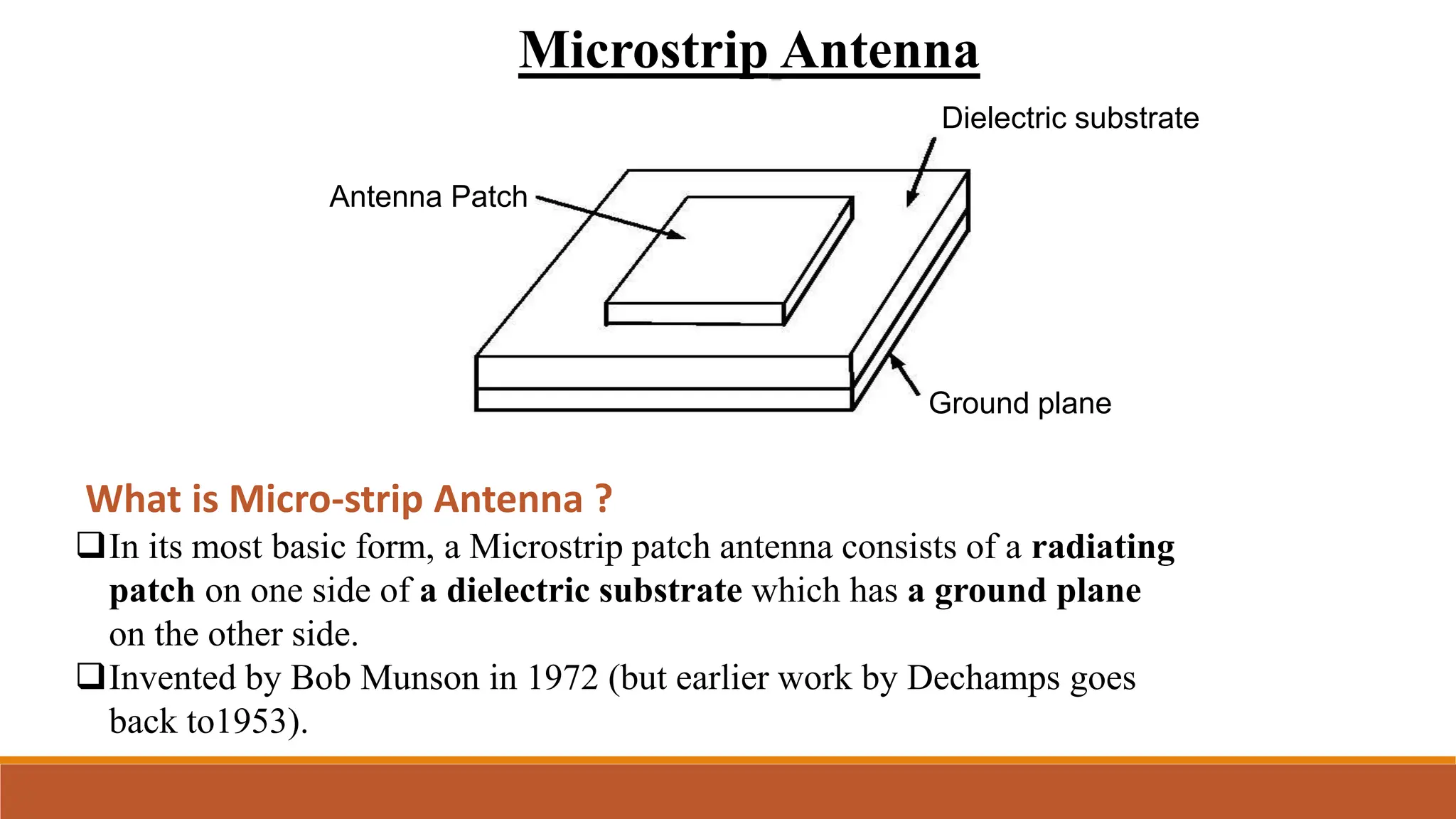
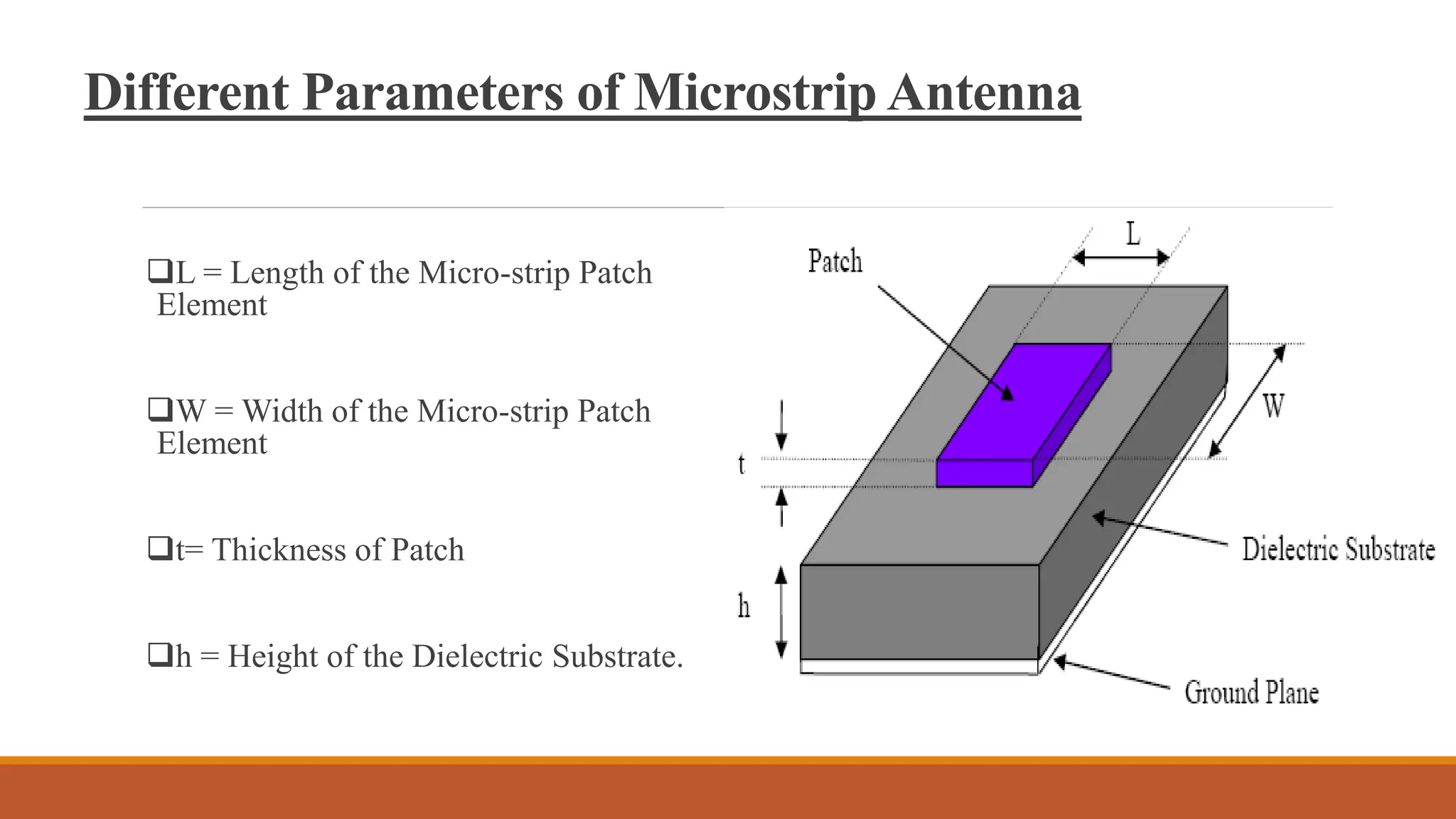
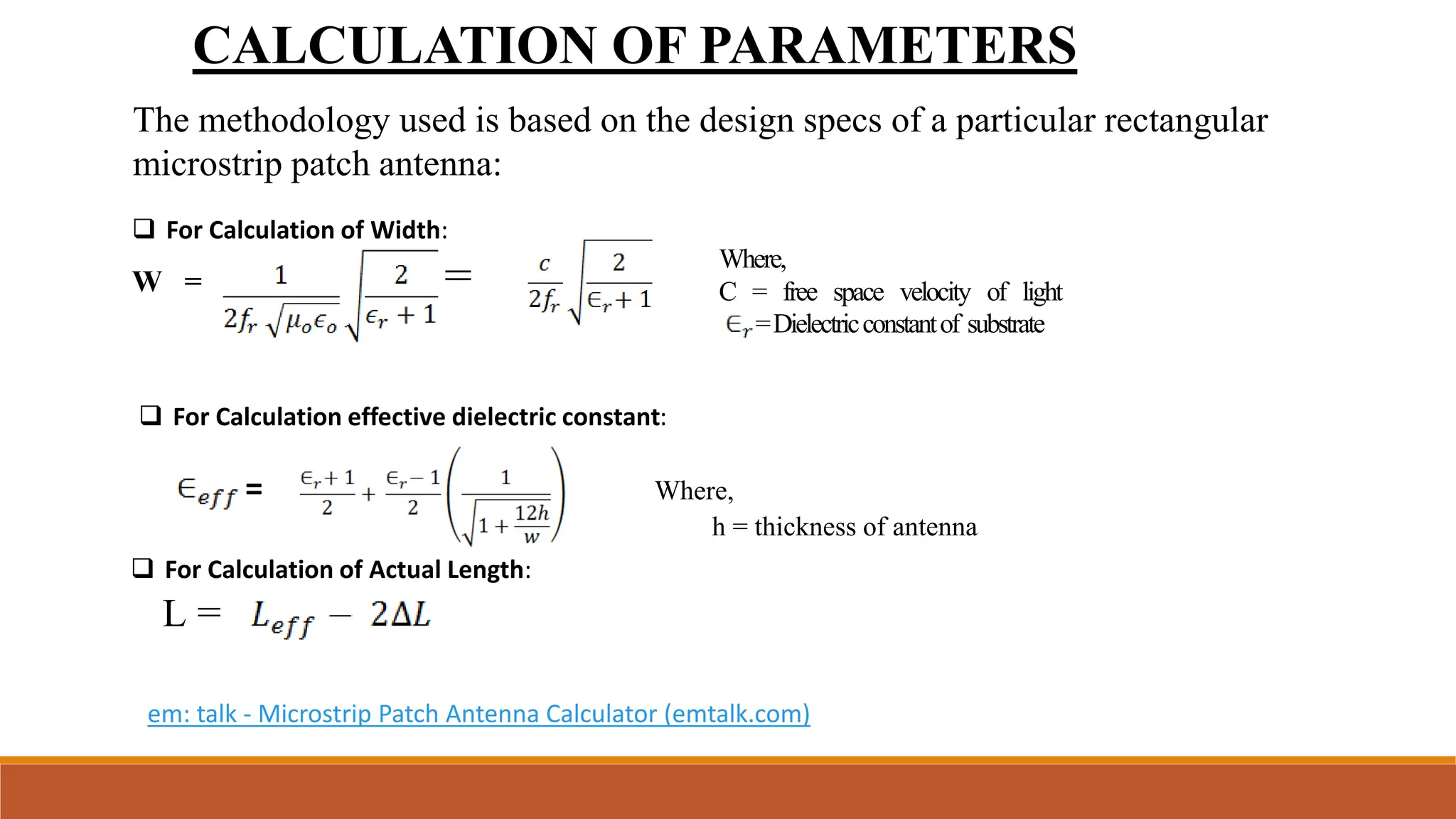
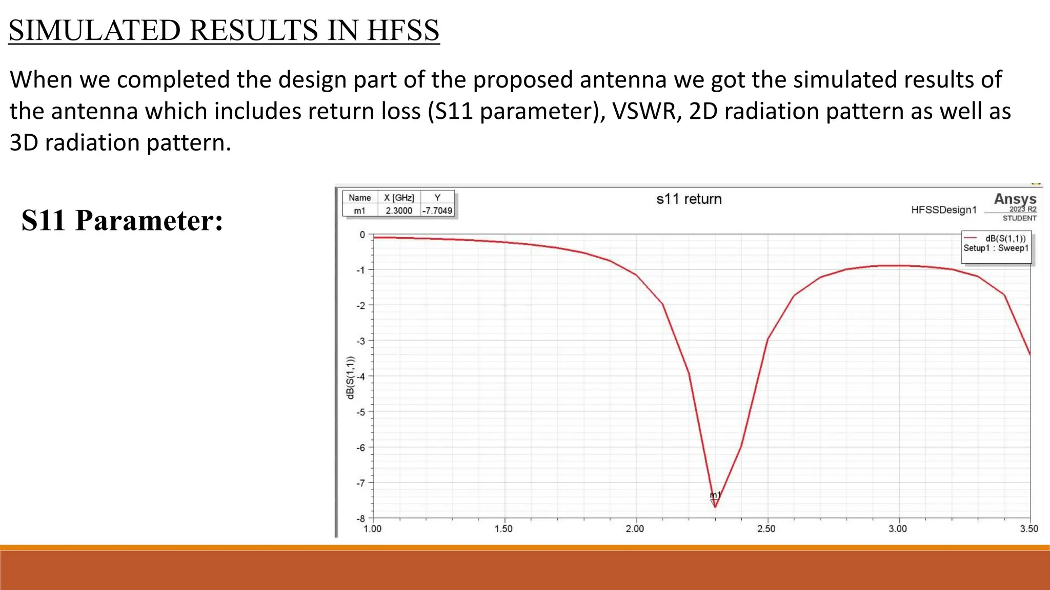
Project Title:- Microstrip patch antenna using Ansys HFSS
Under the kind guidance of
:
PRIYANKA KUMARI
Assisant Lecturer
ECE Department
Presented by:
ROHIT KUMAR (21104147902)
AMAN KUMAR (21104147918)
DEEPAK KUMAR (21104147923)
ROBIN KUMAR (21104147922)
GOVERNMENT ENGINEERINGCOLLEGEAURANGABAD
Department of Electronics & Communication Engg.
TABLE OF CONTENTS
S. NO. TOPICS
1 INTRODUCTION
2 HOW DOES AN ANTENNA WORK
3 MICRO-STRIP PATCH ANTENNA
4 DIFFERENT SHAPES OF MICRO-STRIP PATCH ANTENNA
5 DIFFERENT PARAMETERS OF MICRO-STRIP PATCH ANTENNA
6 CALCULATION OF PARAMETERS
7 BASIC PRINCIPLE OF OPERATION
8 FEED TECHNIQUES
9 ADVANTAGES OF MICRO-STRIP PATCH ANTENNA
10 DISADVANTAGES OF MICRO-STRIP PATCH ANTENNA
11 APPLICATIONS & REMEDIES
INTRODUCTION
Antennas are key components of any wireless system.
An antenna is a device that transmits and/or receives electromagnetic waves.
 Most antennas are resonant devices, which operate efficiently over a relatively narrow
frequency band.
An antenna must be tuned to the same frequency band that the radio system to which
it is connected operates in, otherwise reception and/or transmission will be impaired.
How does an antenna work ?
Antenna is one type of transducer that converts the
electrical energy into the electro-magnetic energy in
form of electromagnetic waves.
Antennas are required by any radio receiver or
transmitter to couple its electrical connection to the
electromagnetic field.
Microstrip Antenna
Antenna Patch
Dielectric substrate
Ground plane
What is Micro-strip Antenna ?
In its most basic form, a Microstrip patch antenna consists of a radiating
patch on one side of a dielectric substrate which has a ground plane
on the other side.
Invented by Bob Munson in 1972 (but earlier work by Dechamps goes
back to1953).
Different Shapes of Micro-strip Patch Elements
Different Parameters of Microstrip Antenna
L = Length of the Micro-strip Patch
Element
W = Width of the Micro-strip Patch
Element
t= Thickness of Patch
h = Height of the Dielectric Substrate.
CALCULATION OF PARAMETERS
The methodology used is based on the design specs of a particular rectangular
microstrip patch antenna:
Where,
C = free space velocity of light
=Dielectricconstantof substrate
 For Calculation of Width:
W = =
 For Calculation effective dielectric constant:
= Where,
h = thickness of antenna
 For Calculation of Actual Length:
L =
em: talk - Microstrip Patch Antenna Calculator (emtalk.com)
Basic Principles of Operation
The patch acts approximately as a resonant cavity (short
circuit walls on top and bottom, open-circuit walls on the
sides).
In a cavity, only certain modes are allowed to exist, at
different resonant frequencies.
 If the antenna is excited at a resonant frequency, a strong
field is set up inside the cavity, and a strong current on the
(bottom) surface of the patch. This produces significant
radiation (a good antenna).
Micro-strip Line Feed.
A conducting strip is connected to the edge
of the patch. The feed can be etched on the
substrate.
Capacitive Feeding
In this type of feeding the feeding
is done to small another patch
instead of main radiating patch.
Feed Techniques
Micro-strip antenna can be feed by variety of methods. This methods can be classified into
two categories-contacting and non-contacting. The foremost popular feed techniques used
are :
 The Coaxial feed or probe feed is a very common technique used for
feeding Microstrip patch antennas.
 The center conductor of the coaxial connecter is soldered to the patch.
Coaxial Feeding
Advantages of Micro-strip Patch Antenna
 Light weight and low volume.
 Low profile planar configuration which can be easily made conformal to host surface.
 Low fabrication cost, hence can be manufactured in large quantities.
 Supports both, linear as well as circular polarization.
 Can be easily integrated with microwave integrated circuits (MICs).
 Capable of dual and triple frequency operations.
 Mechanically robust when mounted on rigid surfaces.
 Useful in aircraft, satellites and missile applications
Disadvantages
 Narrow bandwidth
 Low efficiency
 Low Gain
 Extraneous radiation from feeds and junctions
 Poor end fire radiator except tapered slot antennas
 Low power handling capacity.
 Surface wave excitation.
Applications
 Used in mobile satellite communication system.
 Used in aircraft , spacecraft & missiles
 Direct broad cast television(DBS).
 GPS system.
 Telemetry & telemedicine
 Radar application
Remedies
 Low power and low gain can overcome by arrays configuration.
 Surface wave associated limitations such as poor efficiency,increased mutual coupling,
reduced gain and radiation pattern can overcome.
 The band width can increase up to 60% by using some special techniques.
Software Used To Design Micro-strip Patch
Antenna
HFSS is commercial finite element method
solver for electromagnetic structures from
Ansys Corp.
HFSS stands for High Frequency
Structural Simulator.
It is one of the several commercial tools
used for antenna design .
Its gold-standard accuracy, advanced solver
and compute technology have made it an
essential tool for engineers designing high-
frequency and high-speed electronics
components.
SIMULATED RESULTS IN HFSS
When we completed the design part of the proposed antenna we got the simulated results of
the antenna which includes return loss (S11 parameter), VSWR, 2D radiation pattern as well as
3D radiation pattern.
S11 Parameter:
Voltage Standing Wave Ratio
3D Radiation Pattern
2D RADIATION PATTERN
Conclusion
 The simulation of microstrip patch antenna is carried out.
 The substrate and patches are created.
 The radiation pattern are observed. Rectangular patch antenna at 2.4 GHz is designed on
Ansoft HFSS , dielectric constant = 4.4 and height 2mm
 The designed antenna is suitable for Mobile Communication, Cell Phone Antennas etc.
 The simulation gave results good enough to satisfy our requirements to fabricate it on
hardware which can be used wherever needed.
References
https://www.researchgate.net/publication/351618826_Design_and_Fabrication_of_Microstrip_Patch_
Antenna_at_24_Ghz_for_WLAN_Application_using_HFSS
https://ieeexplore.ieee.org/document/8609703
Nandini Ammanagi, Rahul Khadilkar, Akash Harwani, Disha Budhlani, Disha Dembla; “Comparison of the
performance of Microstrip Antenna at 2.4GHz Using Different Substrate Materials”, International Journal of
Engineering and Advanced Technology
(IJEAT) ISSN: 2249 – 8958, Volume-3, Issue-4, April 2014.
Ogunlade Michael Adegoke; Ismael Saad Eltoum; “Analysis and Design of Rectangular Microstrip Patch Antenna
AT 2.4GhzWLAN Applications”, International Journal of Engineering Research &Technology (IJERT) ISSN: 2278-
0181Vol. 3 Issue 8, August – 2014.

ANSYSS Microstrip patch Anteena using HFSS.pptx

  • 1.
    Project Title:- Microstrippatch antenna using Ansys HFSS Under the kind guidance of : PRIYANKA KUMARI Assisant Lecturer ECE Department Presented by: ROHIT KUMAR (21104147902) AMAN KUMAR (21104147918) DEEPAK KUMAR (21104147923) ROBIN KUMAR (21104147922) GOVERNMENT ENGINEERINGCOLLEGEAURANGABAD Department of Electronics & Communication Engg.
  • 2.
    TABLE OF CONTENTS S.NO. TOPICS 1 INTRODUCTION 2 HOW DOES AN ANTENNA WORK 3 MICRO-STRIP PATCH ANTENNA 4 DIFFERENT SHAPES OF MICRO-STRIP PATCH ANTENNA 5 DIFFERENT PARAMETERS OF MICRO-STRIP PATCH ANTENNA 6 CALCULATION OF PARAMETERS 7 BASIC PRINCIPLE OF OPERATION 8 FEED TECHNIQUES 9 ADVANTAGES OF MICRO-STRIP PATCH ANTENNA 10 DISADVANTAGES OF MICRO-STRIP PATCH ANTENNA 11 APPLICATIONS & REMEDIES
  • 3.
    INTRODUCTION Antennas are keycomponents of any wireless system. An antenna is a device that transmits and/or receives electromagnetic waves.  Most antennas are resonant devices, which operate efficiently over a relatively narrow frequency band. An antenna must be tuned to the same frequency band that the radio system to which it is connected operates in, otherwise reception and/or transmission will be impaired.
  • 4.
    How does anantenna work ? Antenna is one type of transducer that converts the electrical energy into the electro-magnetic energy in form of electromagnetic waves. Antennas are required by any radio receiver or transmitter to couple its electrical connection to the electromagnetic field.
  • 5.
    Microstrip Antenna Antenna Patch Dielectricsubstrate Ground plane What is Micro-strip Antenna ? In its most basic form, a Microstrip patch antenna consists of a radiating patch on one side of a dielectric substrate which has a ground plane on the other side. Invented by Bob Munson in 1972 (but earlier work by Dechamps goes back to1953).
  • 6.
    Different Shapes ofMicro-strip Patch Elements
  • 7.
    Different Parameters ofMicrostrip Antenna L = Length of the Micro-strip Patch Element W = Width of the Micro-strip Patch Element t= Thickness of Patch h = Height of the Dielectric Substrate.
  • 8.
    CALCULATION OF PARAMETERS Themethodology used is based on the design specs of a particular rectangular microstrip patch antenna: Where, C = free space velocity of light =Dielectricconstantof substrate  For Calculation of Width: W = =  For Calculation effective dielectric constant: = Where, h = thickness of antenna  For Calculation of Actual Length: L = em: talk - Microstrip Patch Antenna Calculator (emtalk.com)
  • 9.
    Basic Principles ofOperation The patch acts approximately as a resonant cavity (short circuit walls on top and bottom, open-circuit walls on the sides). In a cavity, only certain modes are allowed to exist, at different resonant frequencies.  If the antenna is excited at a resonant frequency, a strong field is set up inside the cavity, and a strong current on the (bottom) surface of the patch. This produces significant radiation (a good antenna).
  • 10.
    Micro-strip Line Feed. Aconducting strip is connected to the edge of the patch. The feed can be etched on the substrate. Capacitive Feeding In this type of feeding the feeding is done to small another patch instead of main radiating patch. Feed Techniques Micro-strip antenna can be feed by variety of methods. This methods can be classified into two categories-contacting and non-contacting. The foremost popular feed techniques used are :
  • 11.
     The Coaxialfeed or probe feed is a very common technique used for feeding Microstrip patch antennas.  The center conductor of the coaxial connecter is soldered to the patch. Coaxial Feeding
  • 12.
    Advantages of Micro-stripPatch Antenna  Light weight and low volume.  Low profile planar configuration which can be easily made conformal to host surface.  Low fabrication cost, hence can be manufactured in large quantities.  Supports both, linear as well as circular polarization.  Can be easily integrated with microwave integrated circuits (MICs).  Capable of dual and triple frequency operations.  Mechanically robust when mounted on rigid surfaces.  Useful in aircraft, satellites and missile applications
  • 13.
    Disadvantages  Narrow bandwidth Low efficiency  Low Gain  Extraneous radiation from feeds and junctions  Poor end fire radiator except tapered slot antennas  Low power handling capacity.  Surface wave excitation.
  • 14.
    Applications  Used inmobile satellite communication system.  Used in aircraft , spacecraft & missiles  Direct broad cast television(DBS).  GPS system.  Telemetry & telemedicine  Radar application Remedies  Low power and low gain can overcome by arrays configuration.  Surface wave associated limitations such as poor efficiency,increased mutual coupling, reduced gain and radiation pattern can overcome.  The band width can increase up to 60% by using some special techniques.
  • 15.
    Software Used ToDesign Micro-strip Patch Antenna HFSS is commercial finite element method solver for electromagnetic structures from Ansys Corp. HFSS stands for High Frequency Structural Simulator. It is one of the several commercial tools used for antenna design . Its gold-standard accuracy, advanced solver and compute technology have made it an essential tool for engineers designing high- frequency and high-speed electronics components.
  • 16.
    SIMULATED RESULTS INHFSS When we completed the design part of the proposed antenna we got the simulated results of the antenna which includes return loss (S11 parameter), VSWR, 2D radiation pattern as well as 3D radiation pattern. S11 Parameter:
  • 17.
  • 18.
  • 19.
  • 20.
    Conclusion  The simulationof microstrip patch antenna is carried out.  The substrate and patches are created.  The radiation pattern are observed. Rectangular patch antenna at 2.4 GHz is designed on Ansoft HFSS , dielectric constant = 4.4 and height 2mm  The designed antenna is suitable for Mobile Communication, Cell Phone Antennas etc.  The simulation gave results good enough to satisfy our requirements to fabricate it on hardware which can be used wherever needed.
  • 21.
    References https://www.researchgate.net/publication/351618826_Design_and_Fabrication_of_Microstrip_Patch_ Antenna_at_24_Ghz_for_WLAN_Application_using_HFSS https://ieeexplore.ieee.org/document/8609703 Nandini Ammanagi, RahulKhadilkar, Akash Harwani, Disha Budhlani, Disha Dembla; “Comparison of the performance of Microstrip Antenna at 2.4GHz Using Different Substrate Materials”, International Journal of Engineering and Advanced Technology (IJEAT) ISSN: 2249 – 8958, Volume-3, Issue-4, April 2014. Ogunlade Michael Adegoke; Ismael Saad Eltoum; “Analysis and Design of Rectangular Microstrip Patch Antenna AT 2.4GhzWLAN Applications”, International Journal of Engineering Research &Technology (IJERT) ISSN: 2278- 0181Vol. 3 Issue 8, August – 2014.