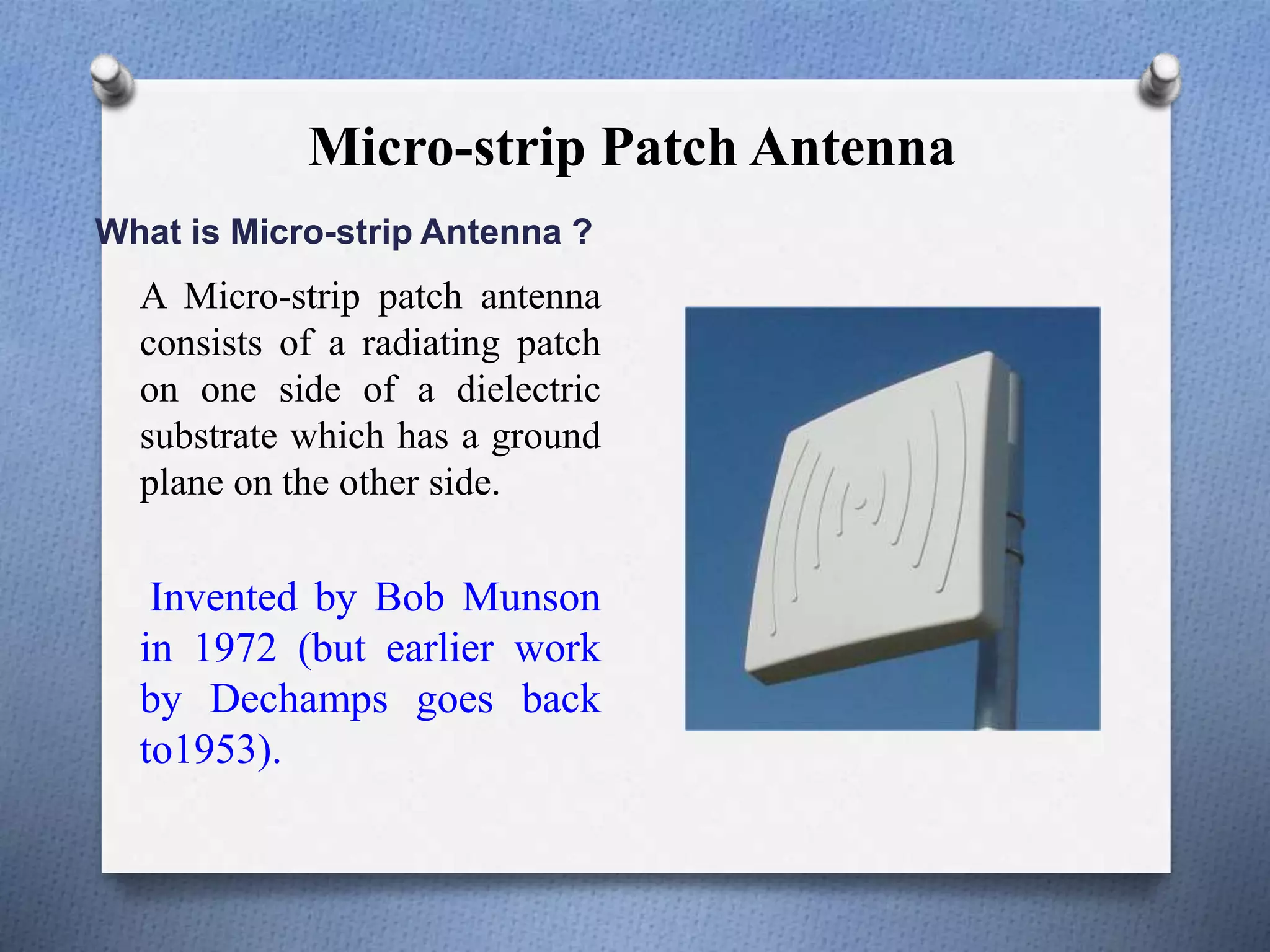
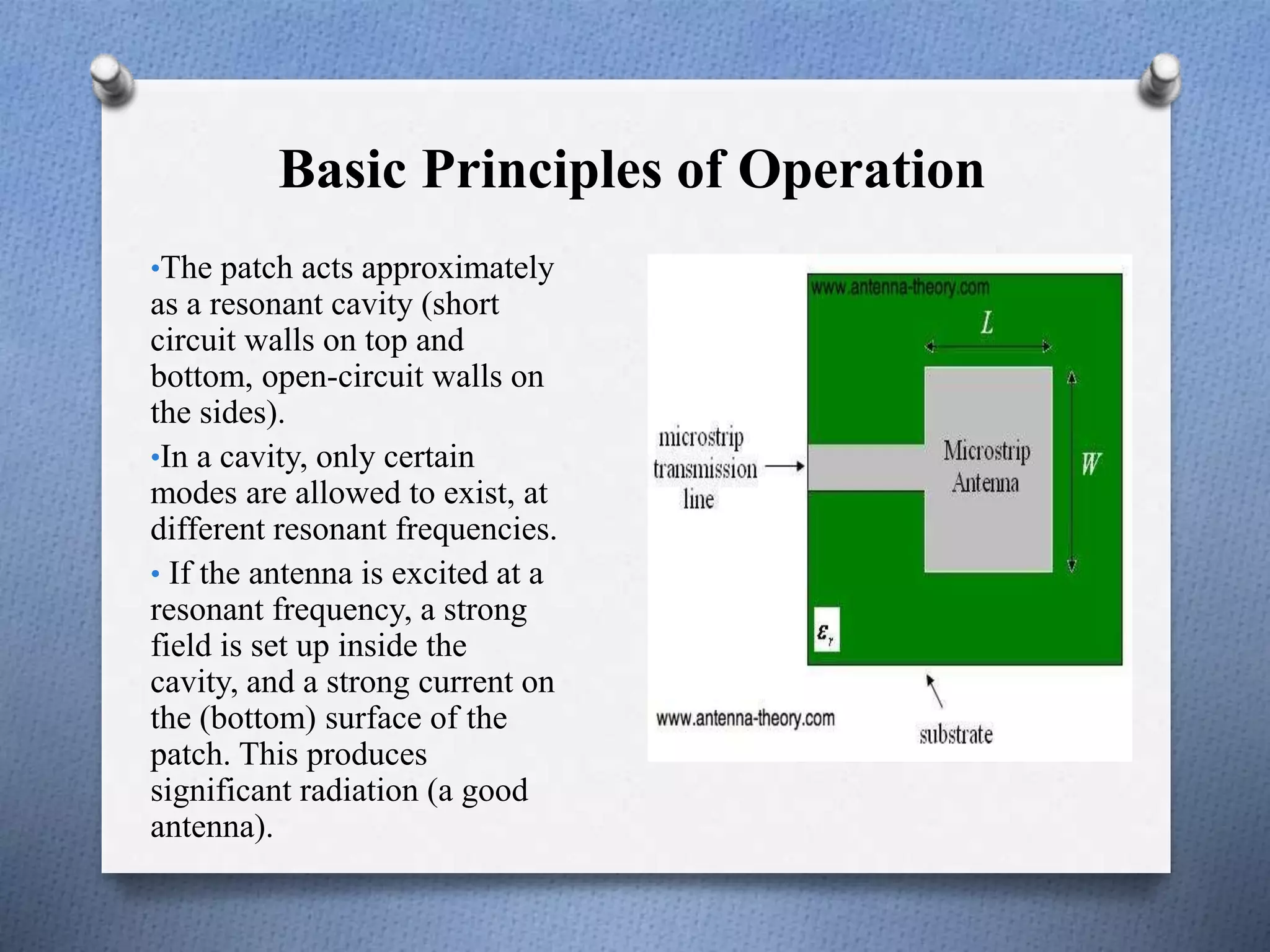
1) The document discusses the design of a micro-strip slot antenna with polarization using HFSS software. It describes the basic working principles and characteristics of micro-strip patch antennas.
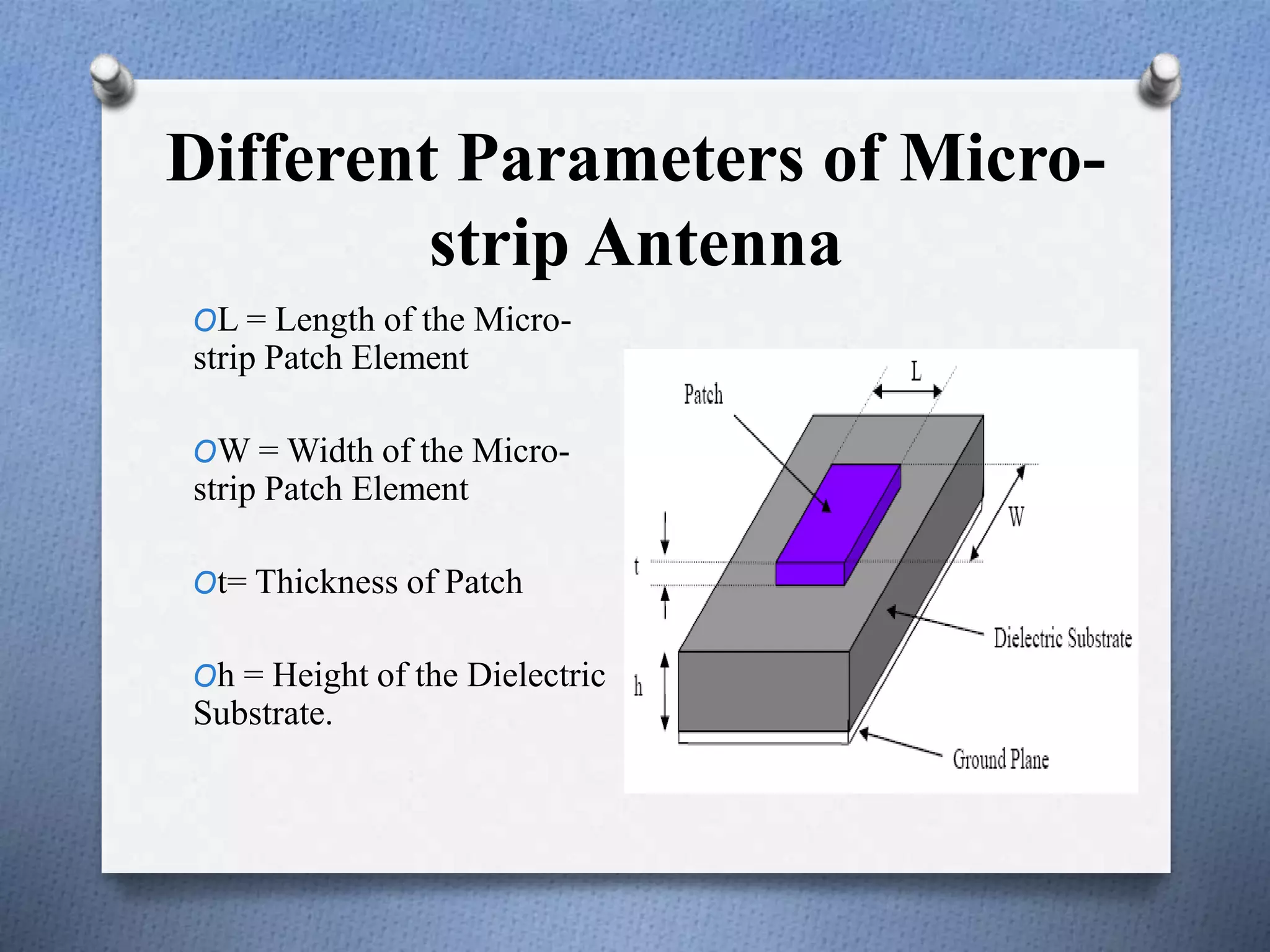
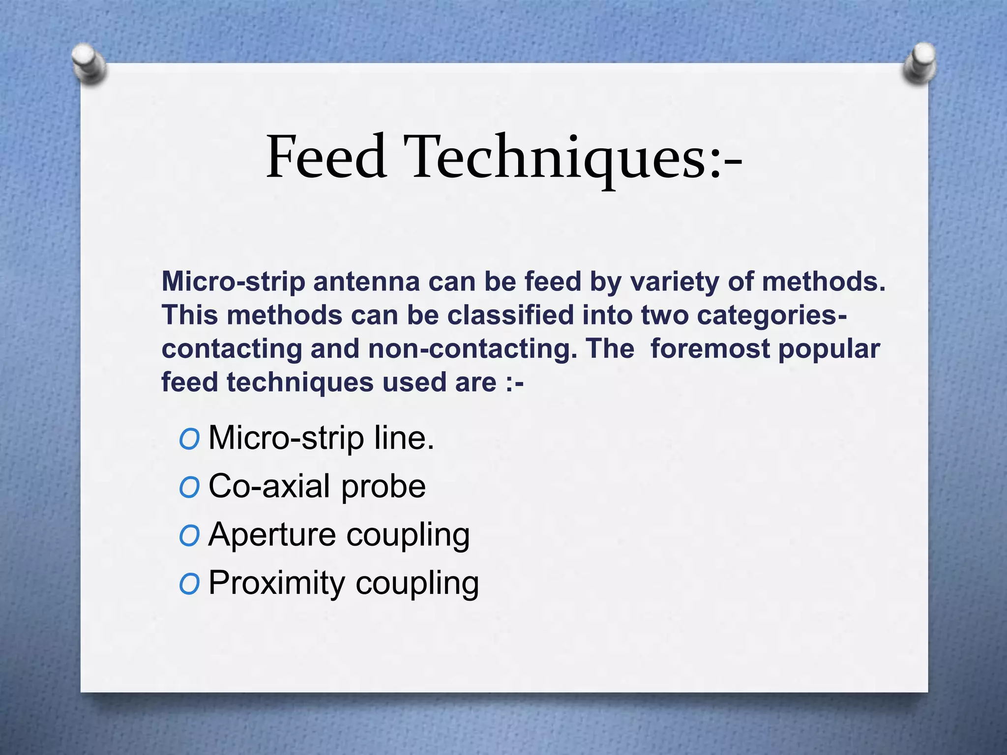
2) The design specifications and calculations to determine the parameters of the antenna like length, width, and frequency are shown. Various feed techniques for micro-strip antennas are also covered.
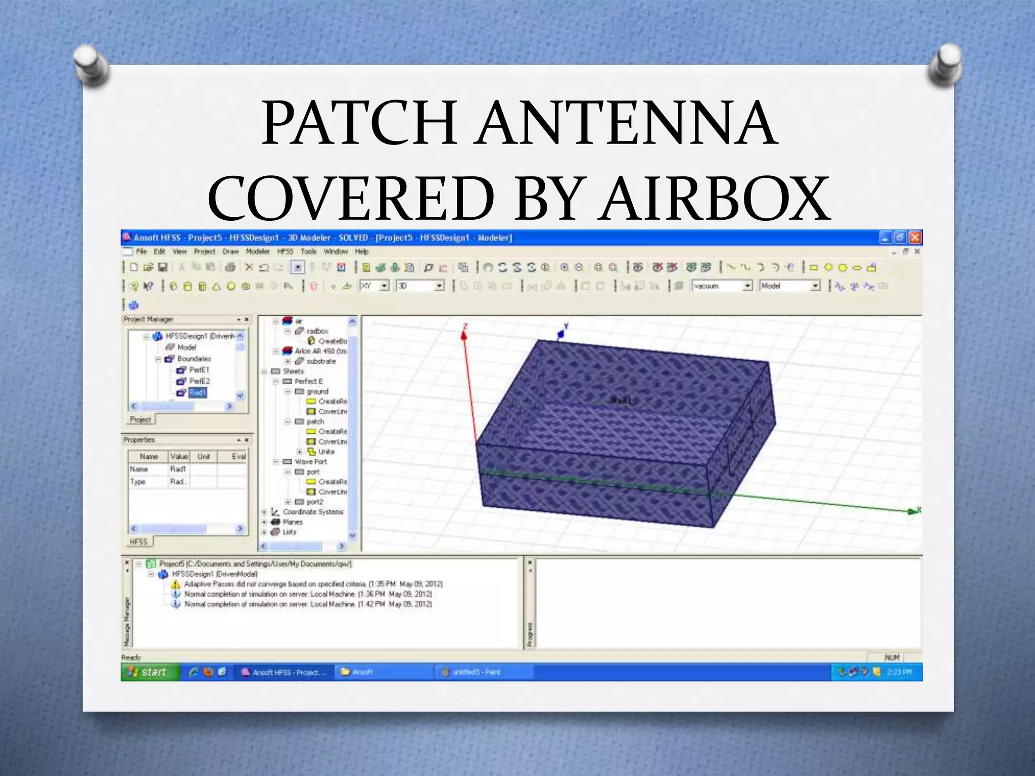
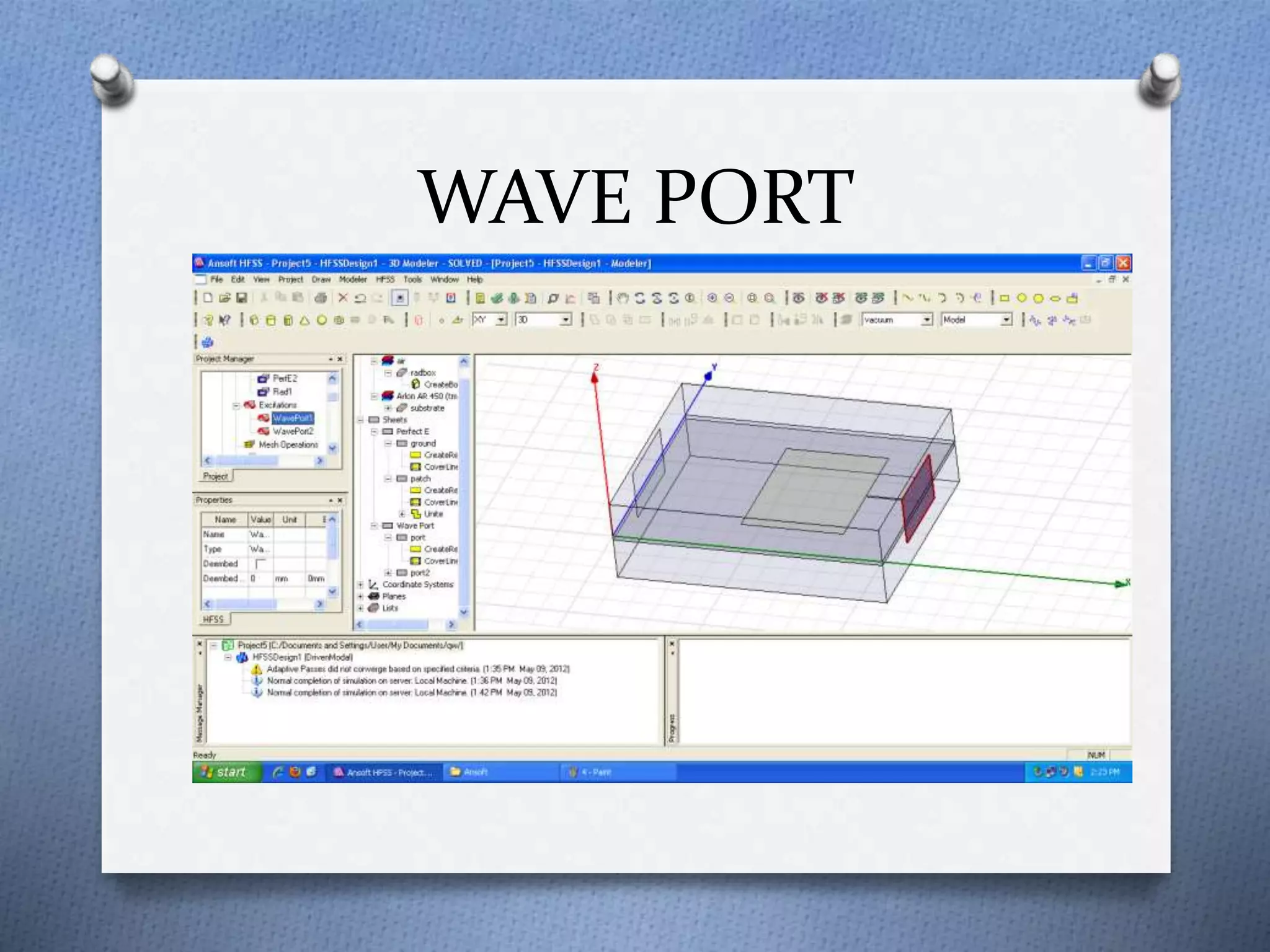
3) The document concludes that the micro-strip antenna was successfully designed using HFSS software based on the microstrip feed line technique and discusses potential applications.