Downloaded 365 times
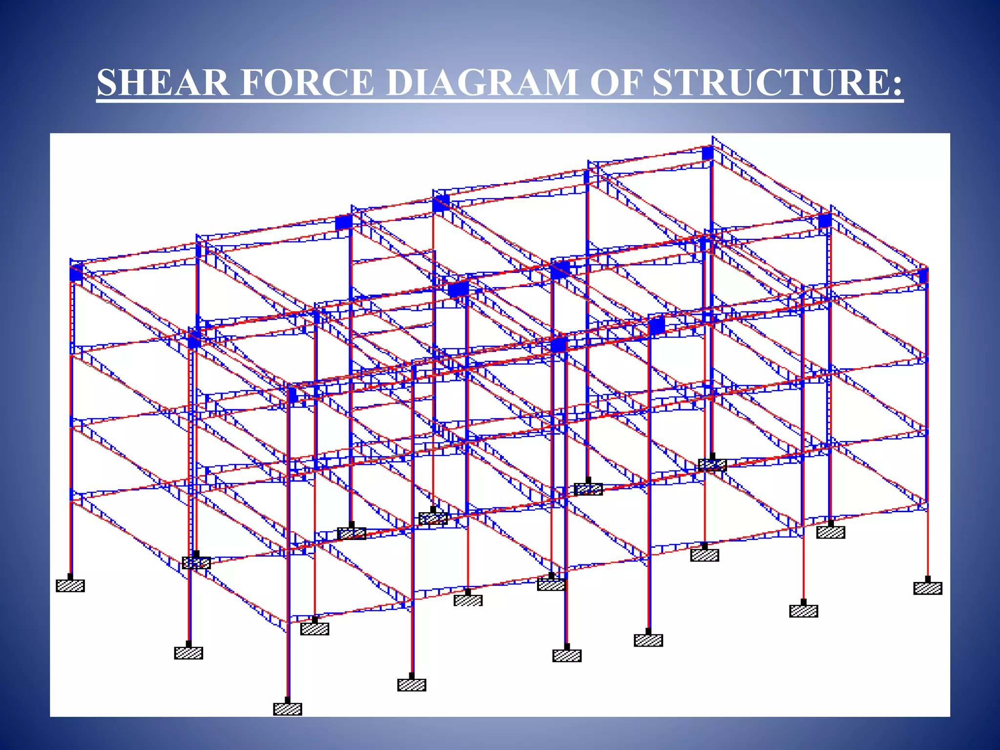


This document provides an analysis and design of a G+3 residential building. It includes details of the building such as dimensions, material properties, and load calculations. An equivalent static analysis is performed to calculate the seismic lateral loads at each floor level. The results of the structural analysis including bending moment and shear force diagrams are presented. Slab, beam, column and footing designs are to be covered in the thesis work according to the scope.
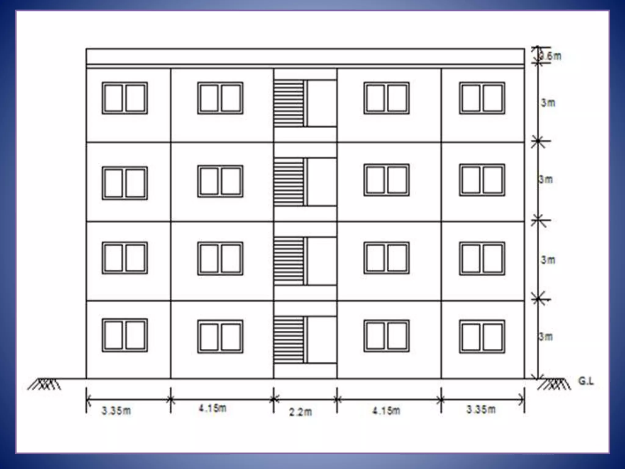
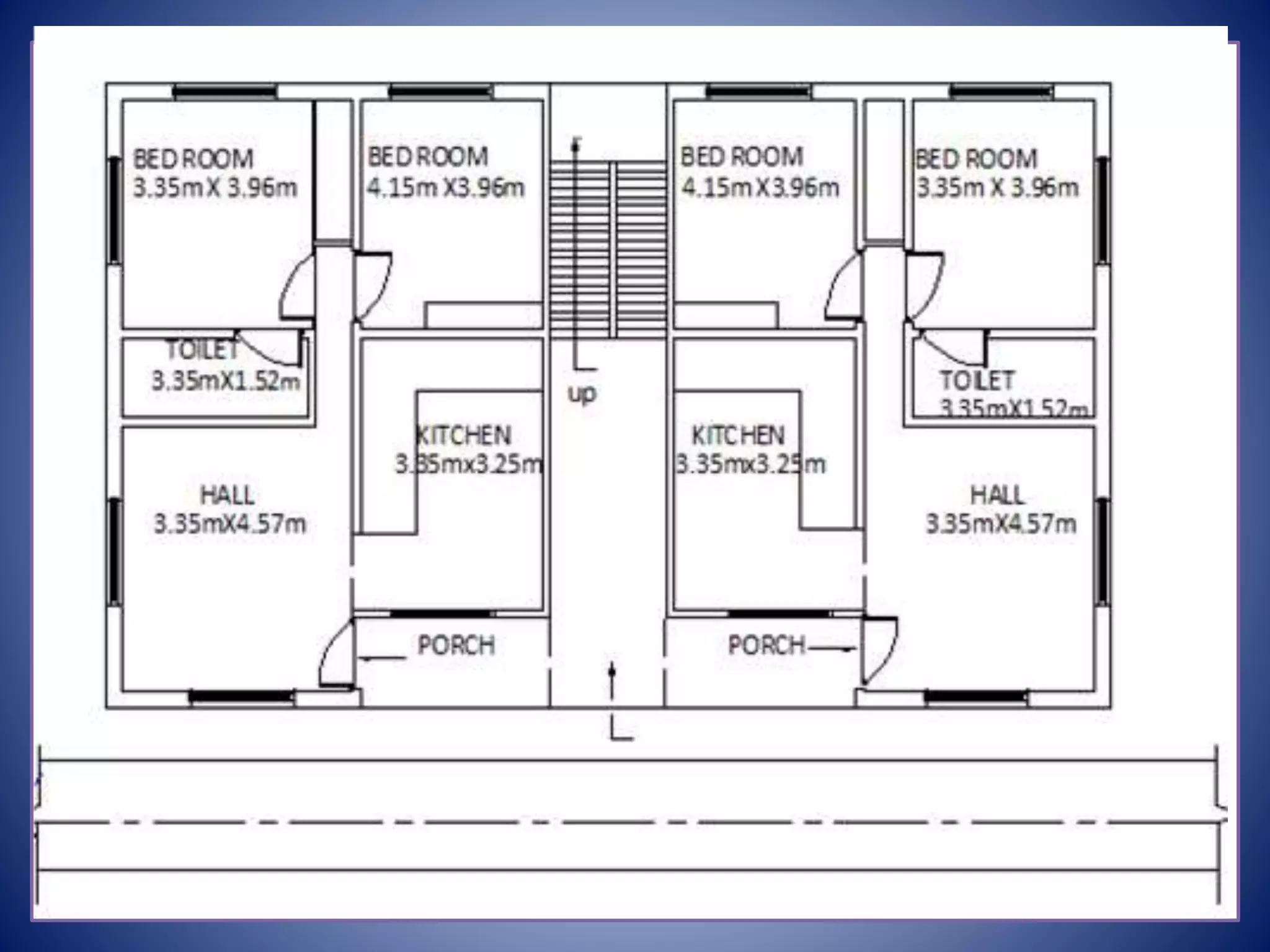
Overview of the G+3 structure analysis, including aims, scope, and methods for gravity and lateral load analysis.
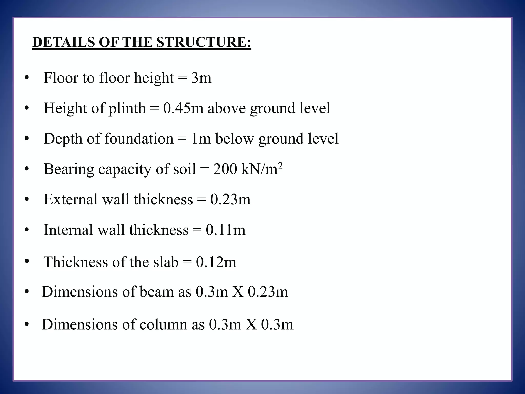
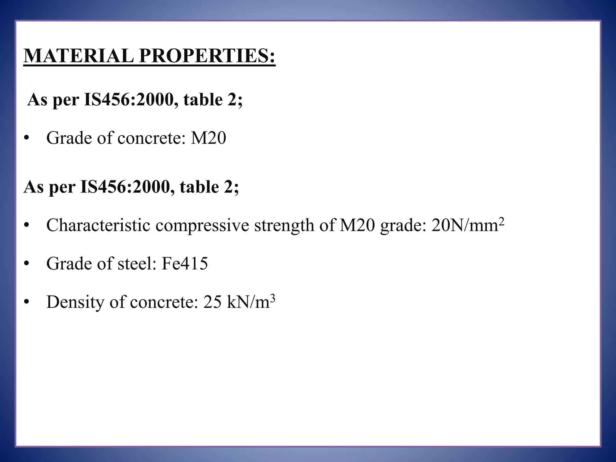
Specifications of structure dimensions and material properties, including concrete and steel grades.
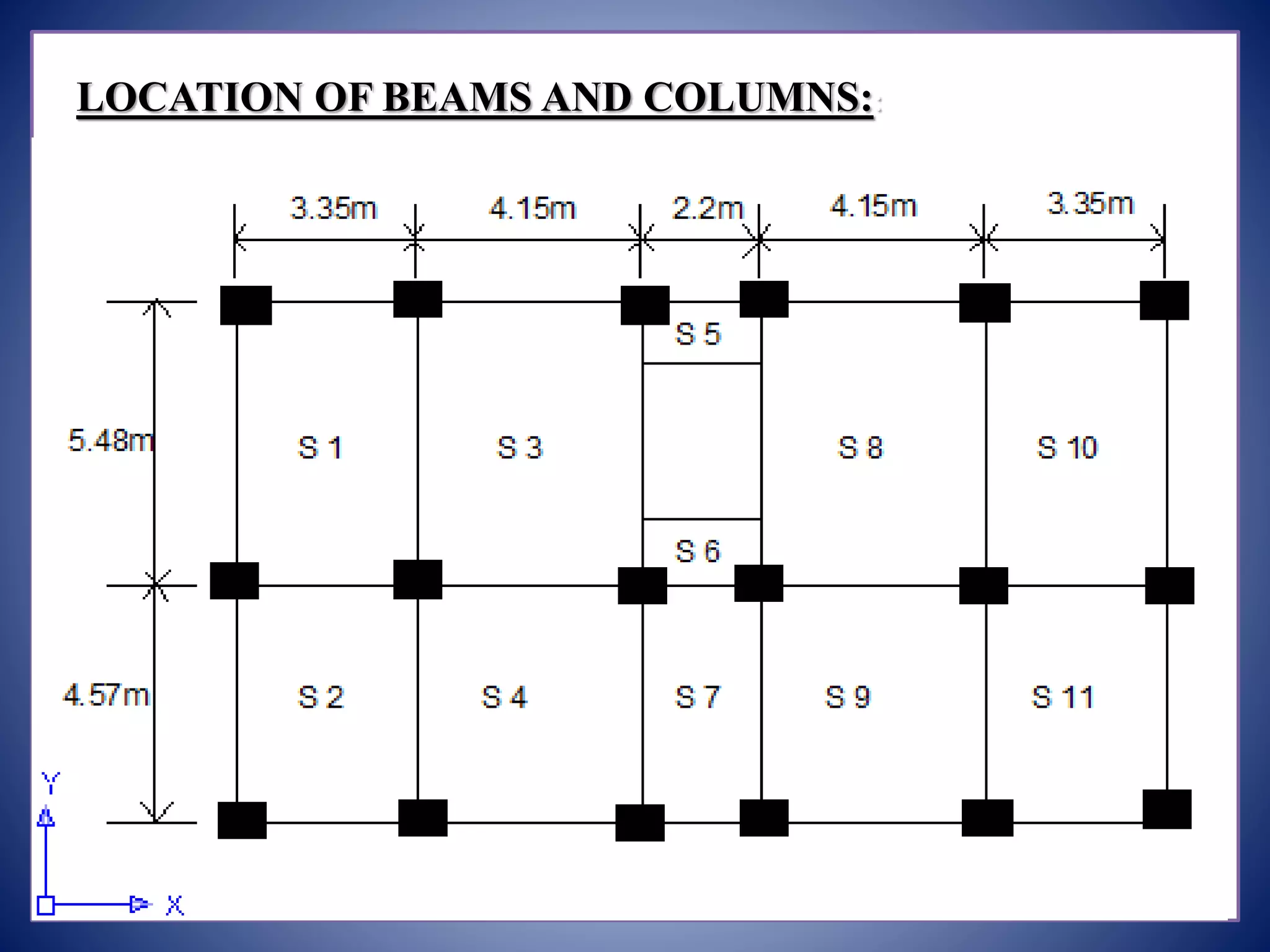
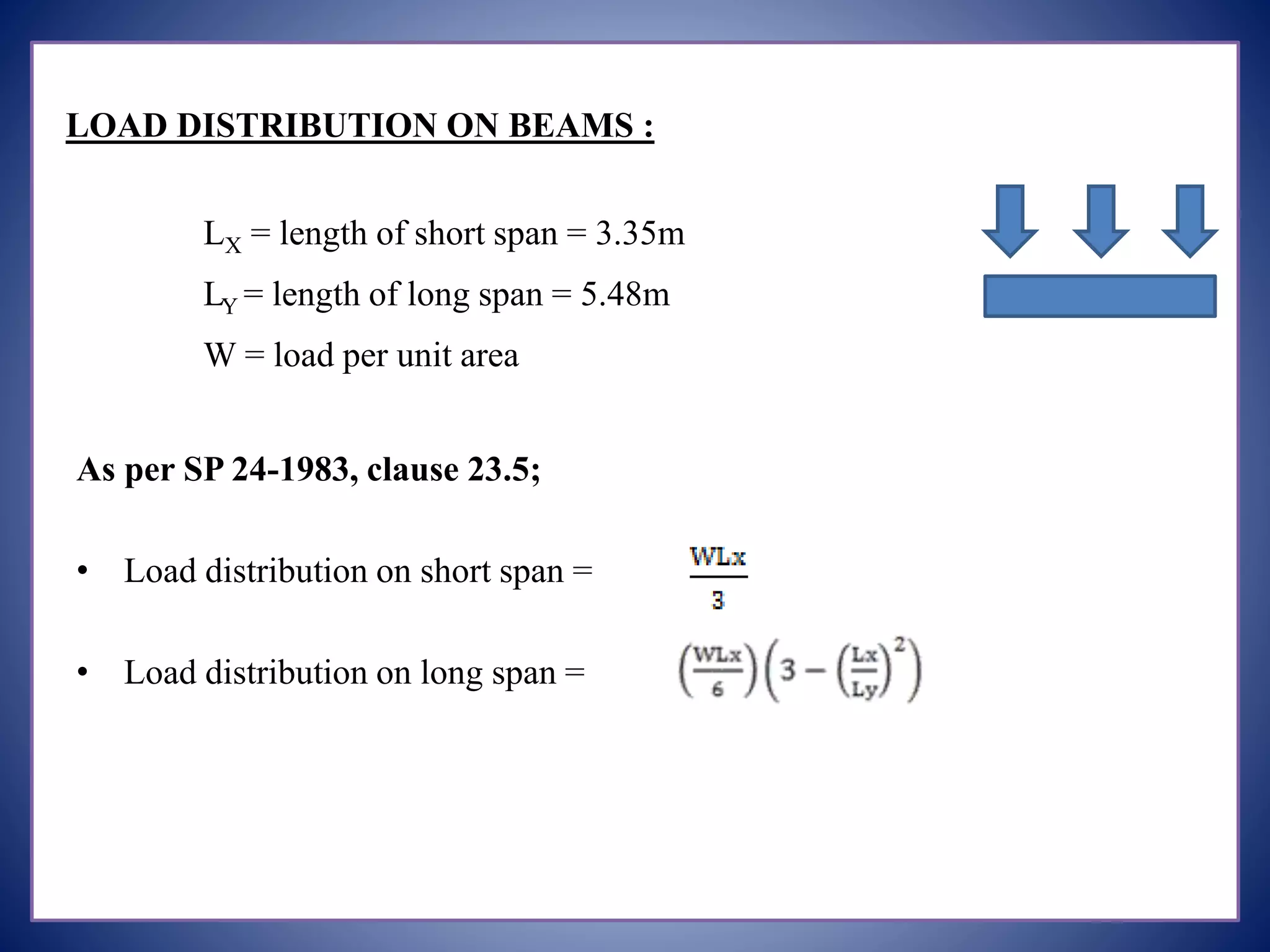
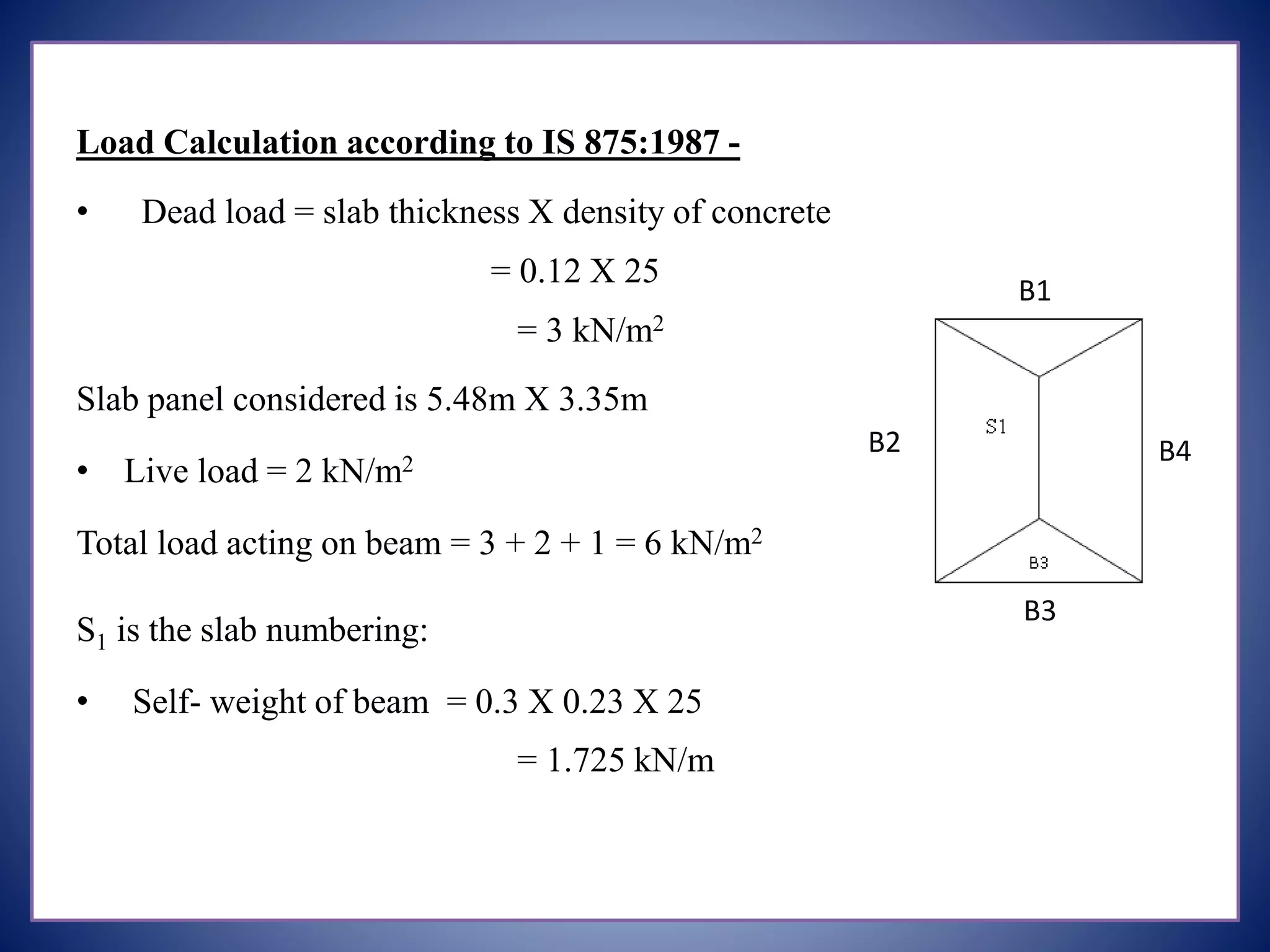
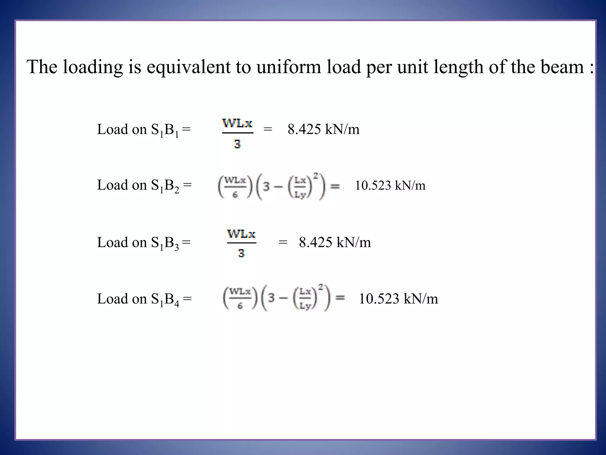
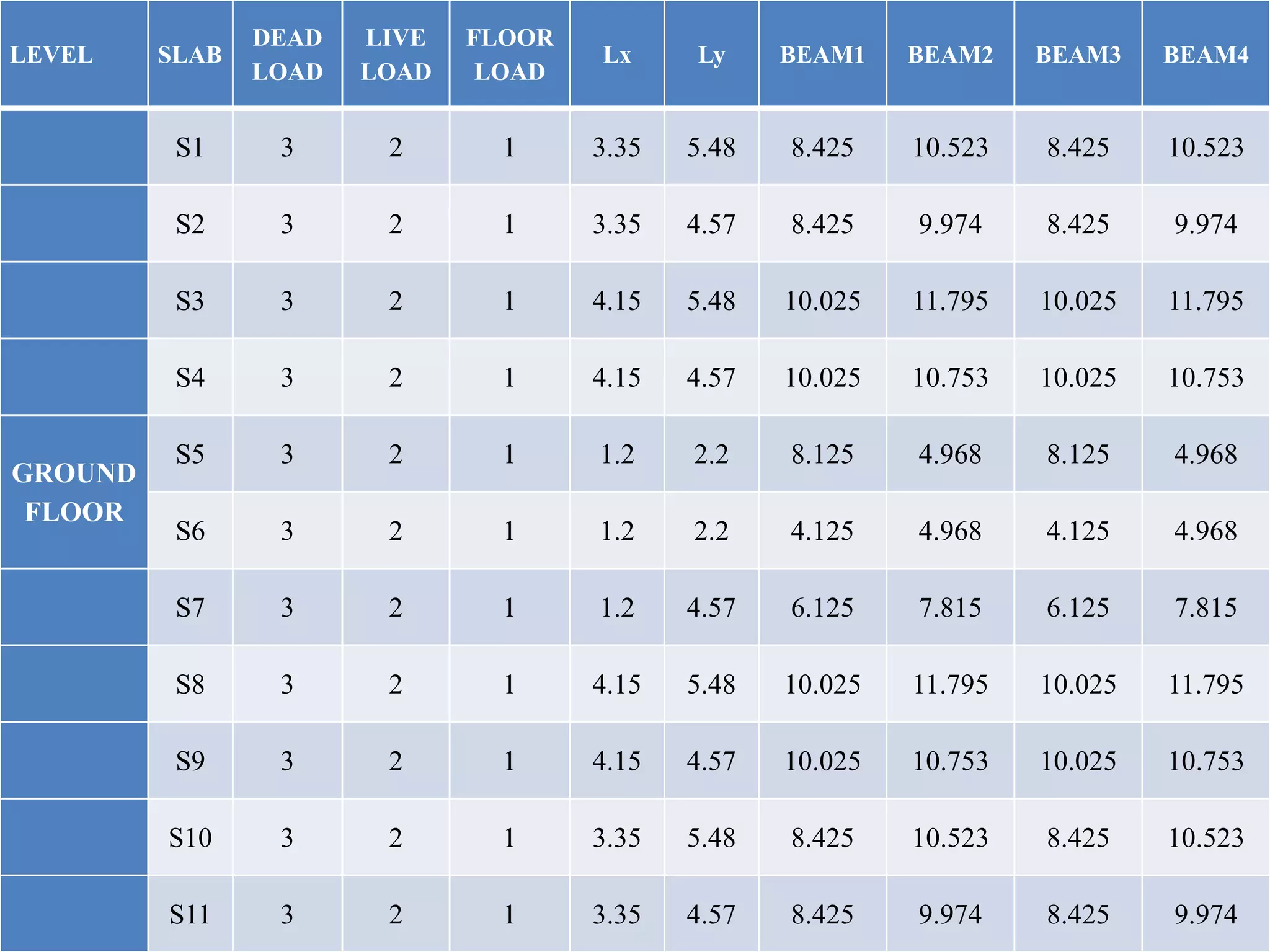
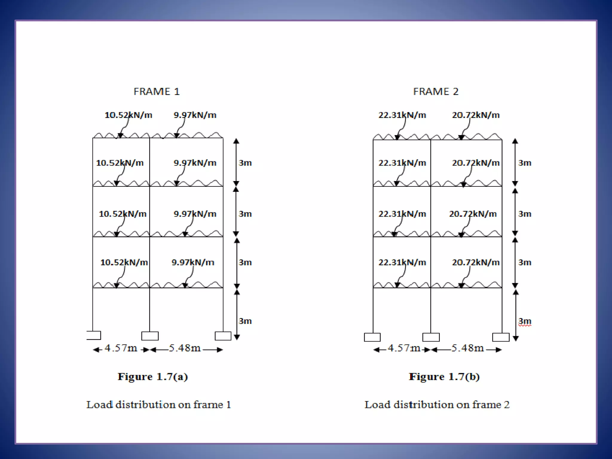
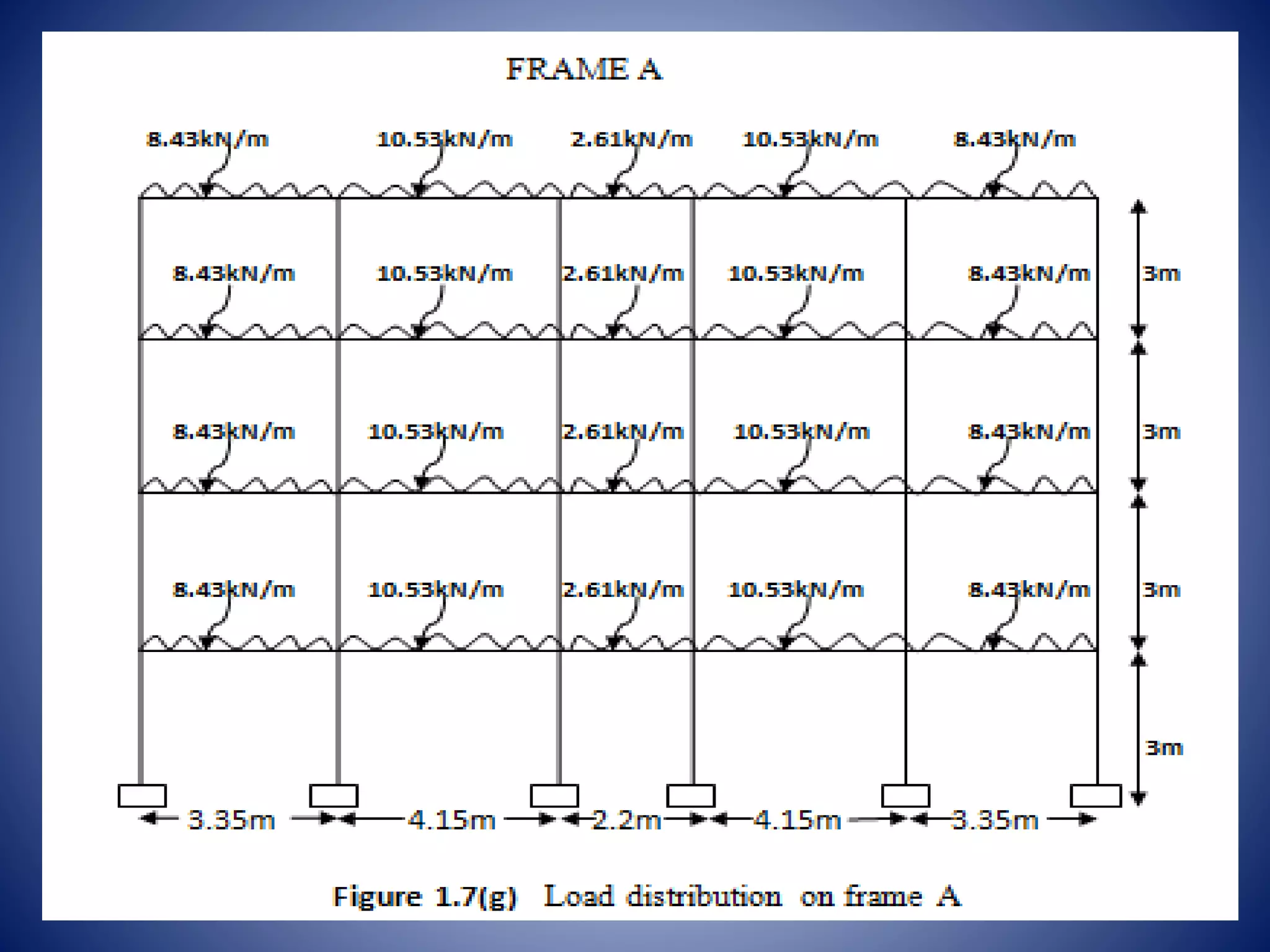
Load distribution on beams and detailed calculations for dead and live loads affecting the structure.
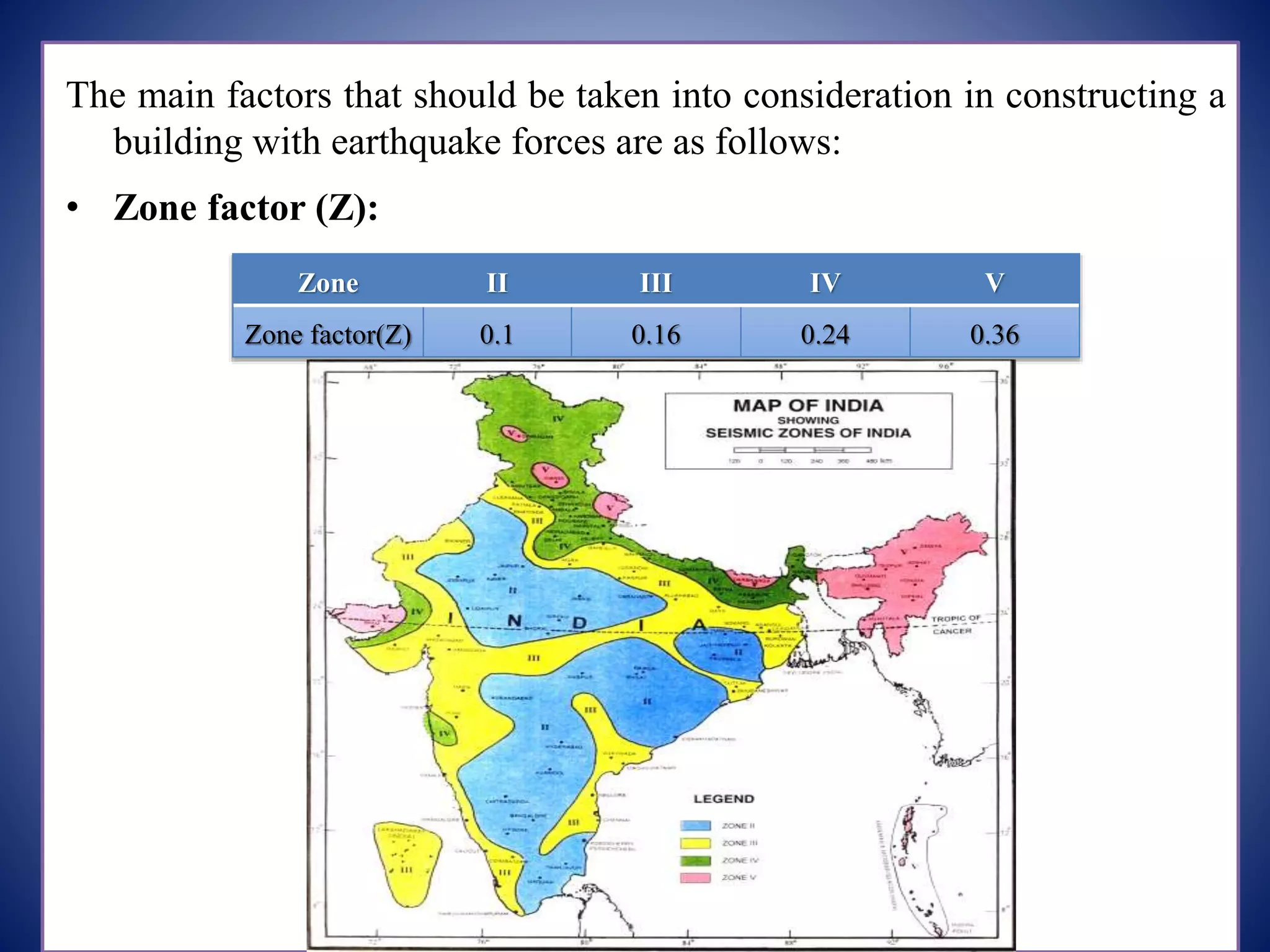
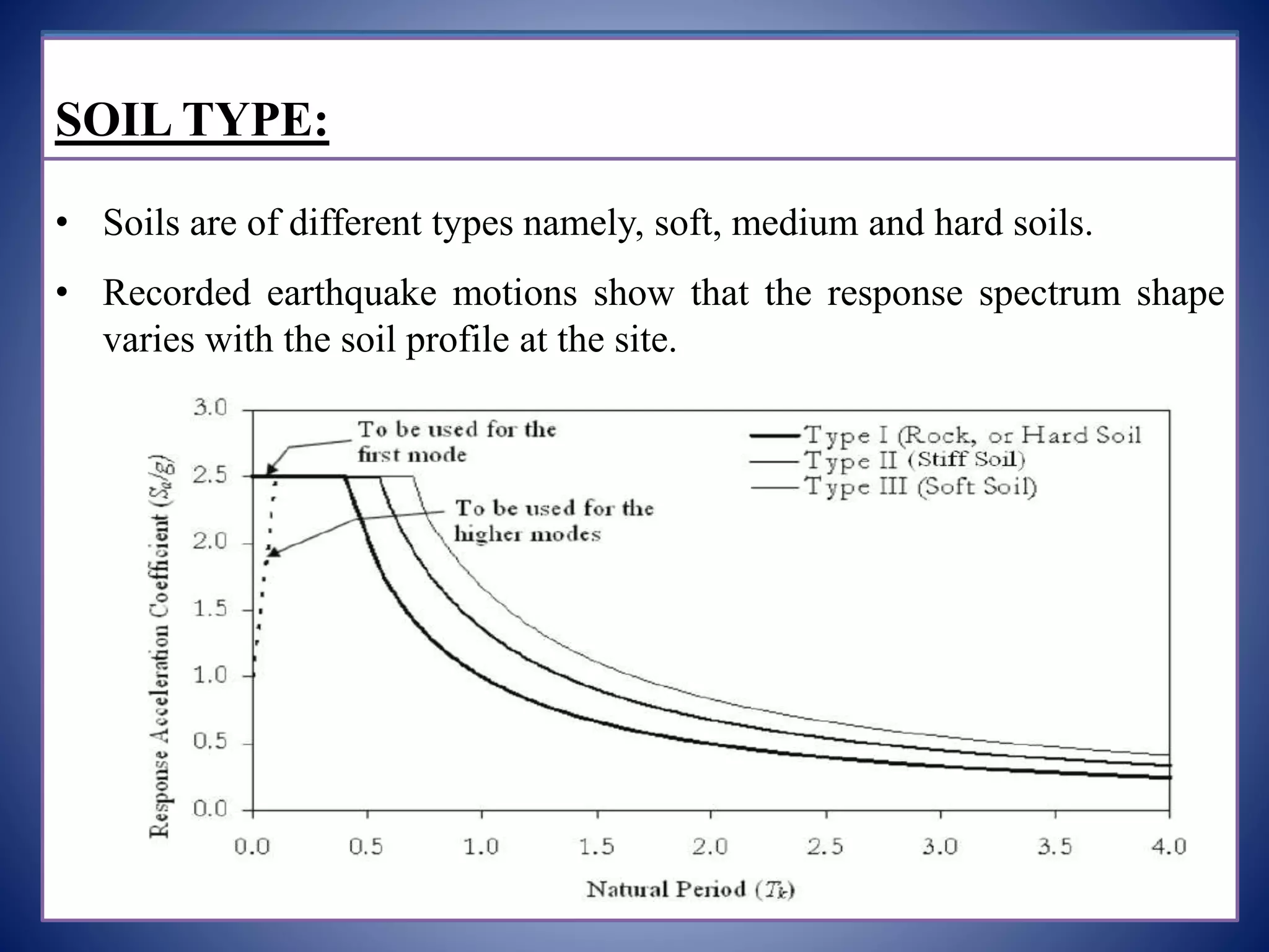
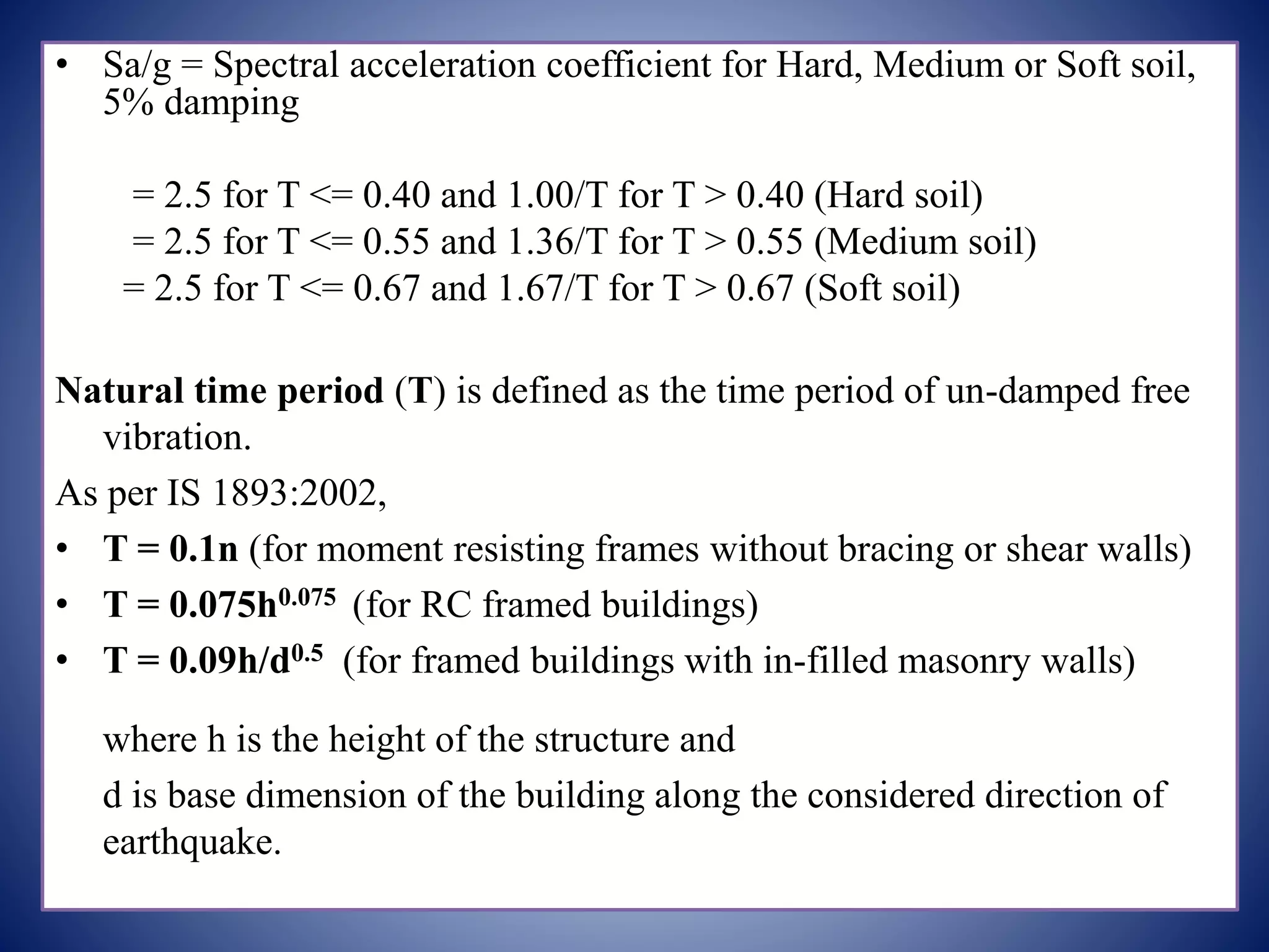
Equations for seismic analysis like base shear, consideration of earthquake zones, soil types, and importance factors.
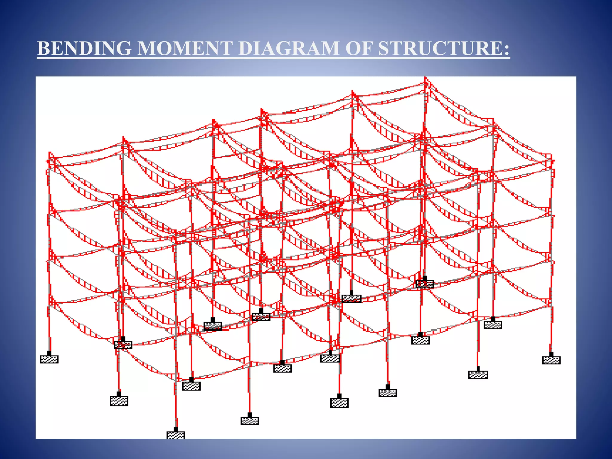
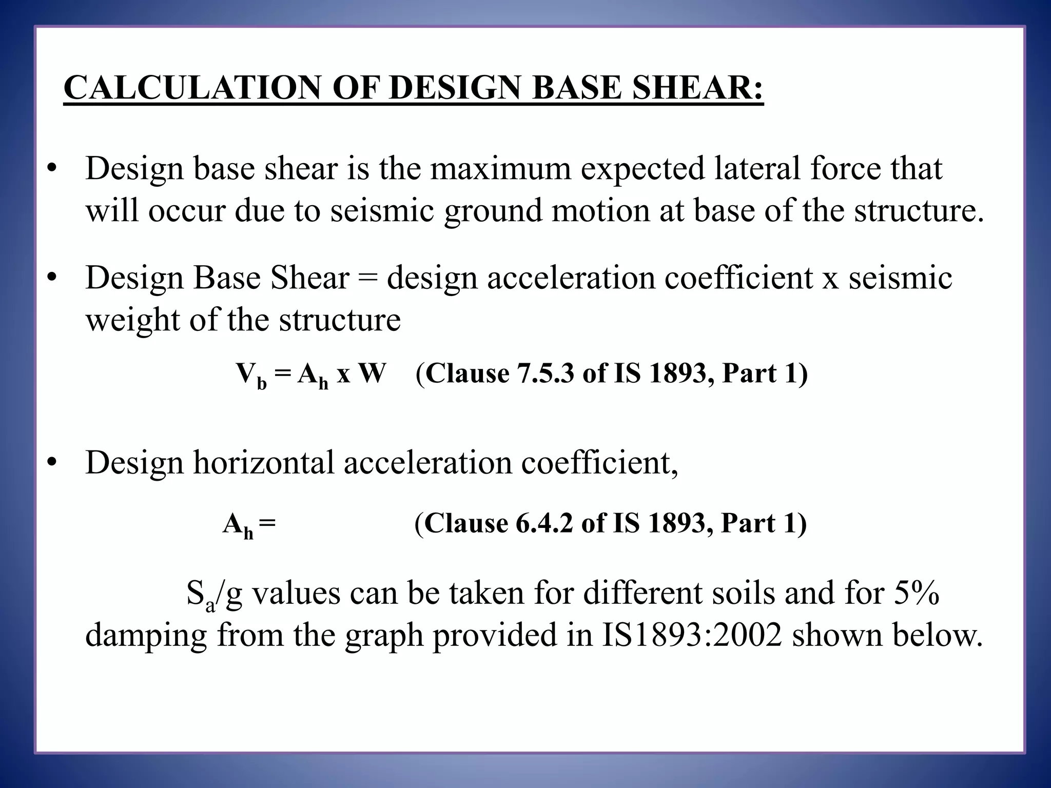
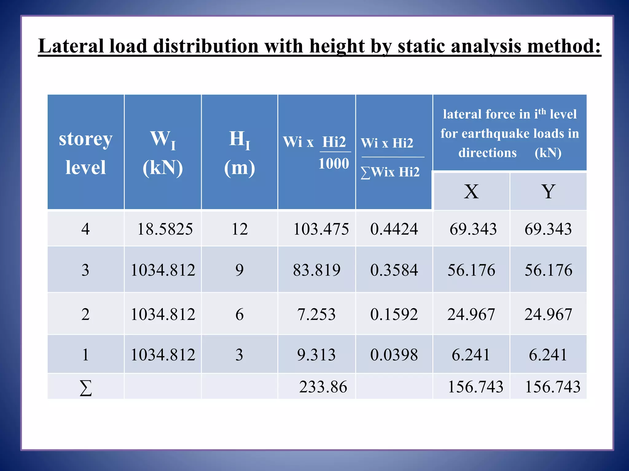
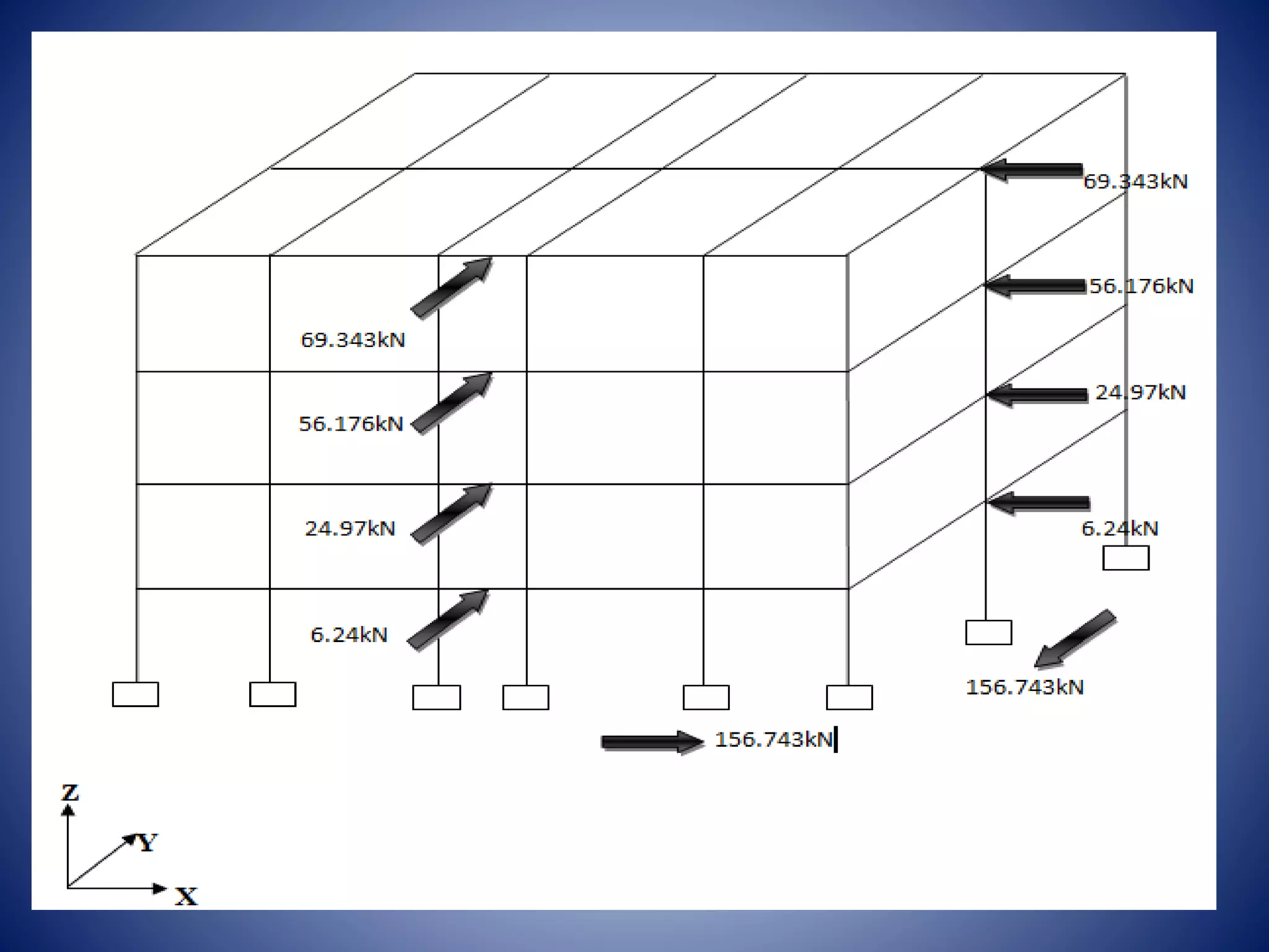
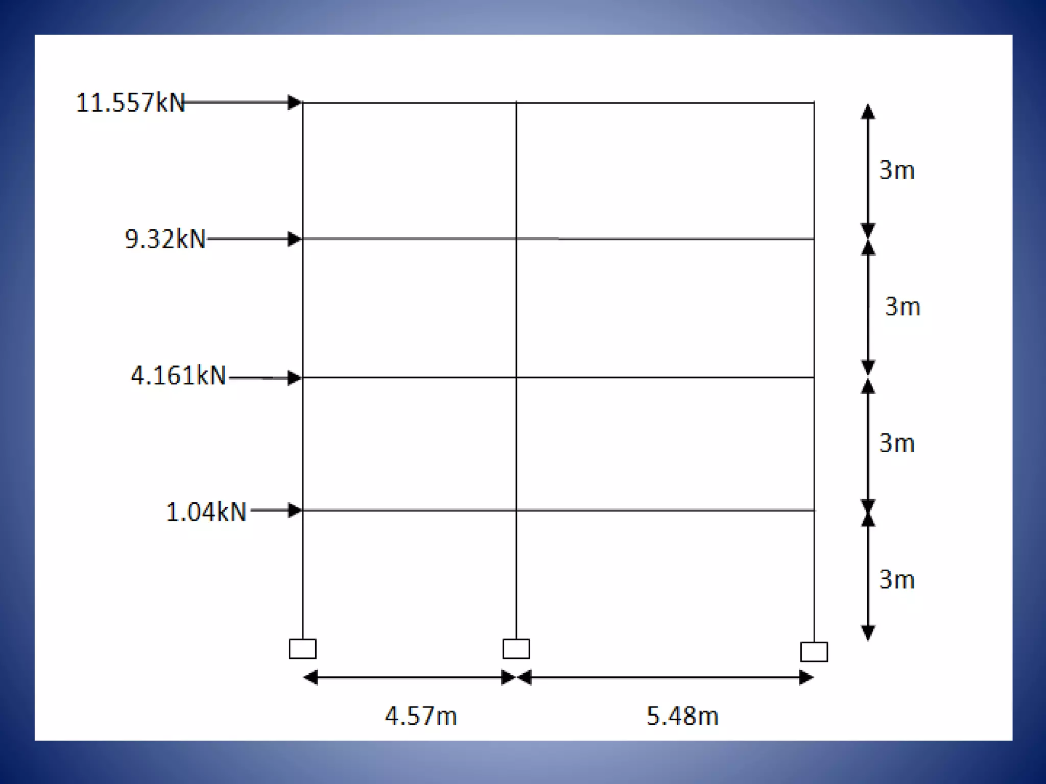
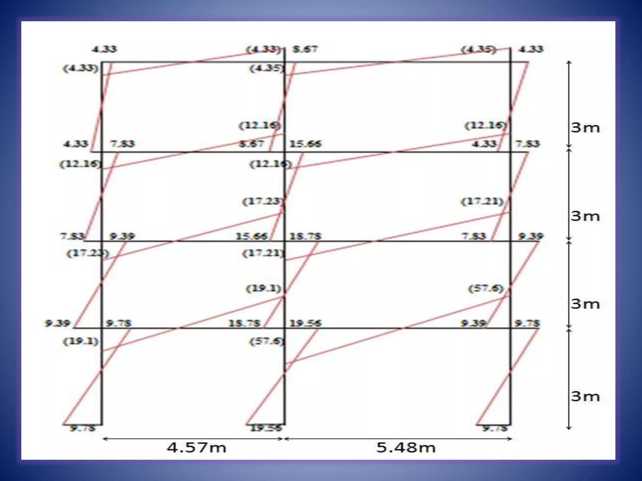
Calculation methods for design base shear, spectral acceleration coefficients, and static analysis of lateral loads.
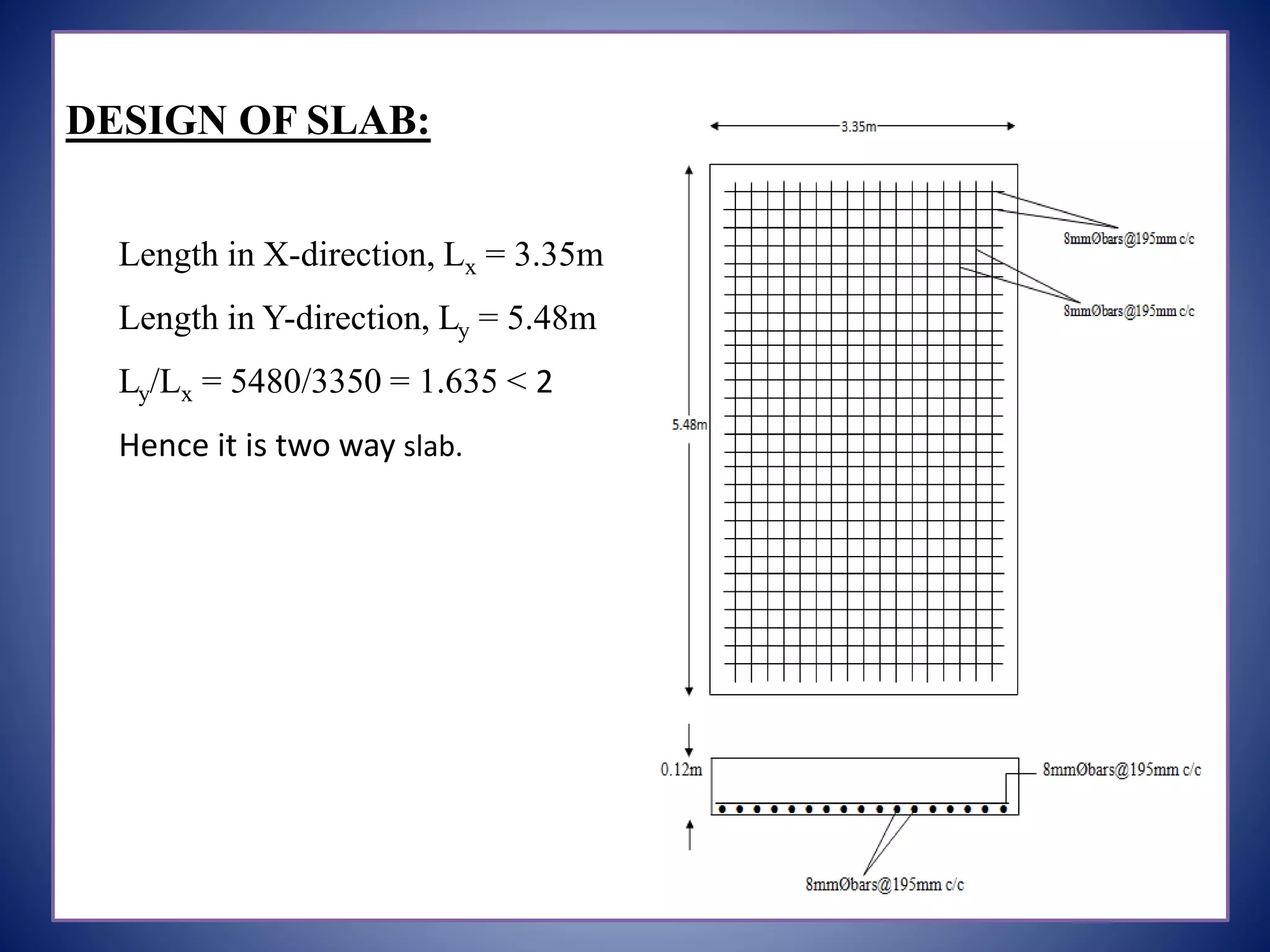
Design aspects of slabs and beams, including reinforcement types for structural integrity.


![ANPARA THERMAL POWER STATION[1] sangam.pdf](https://cdn.slidesharecdn.com/ss_thumbnails/anparathermalpowerstation1sangam-251121115219-9261cde4-thumbnail.jpg?width=640&height=640&fit=bounds)


