This document provides an overview of structural design concepts and processes. It discusses:
1. The overall design process including conception, modeling, analysis, design, detailing, drafting and costing.
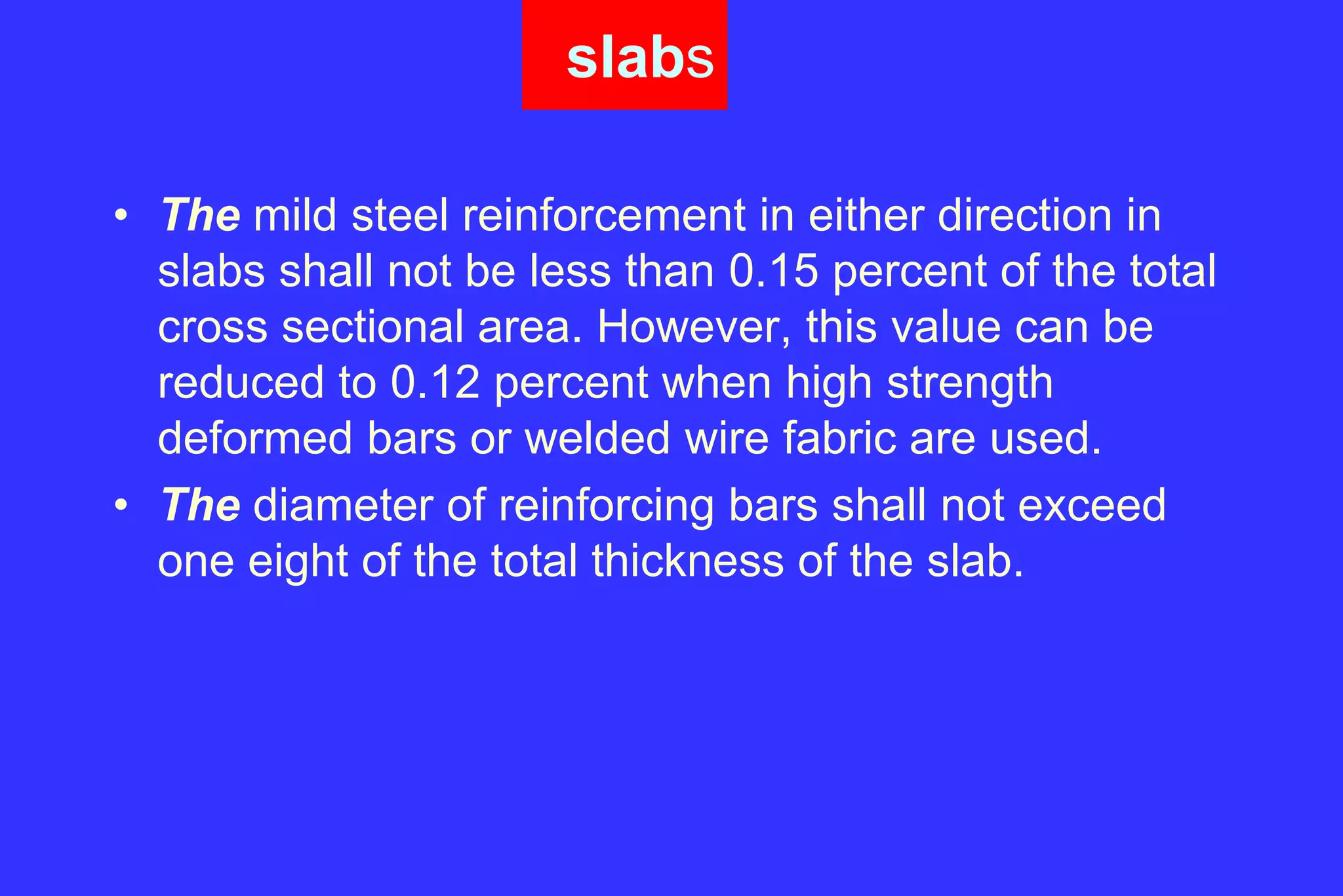
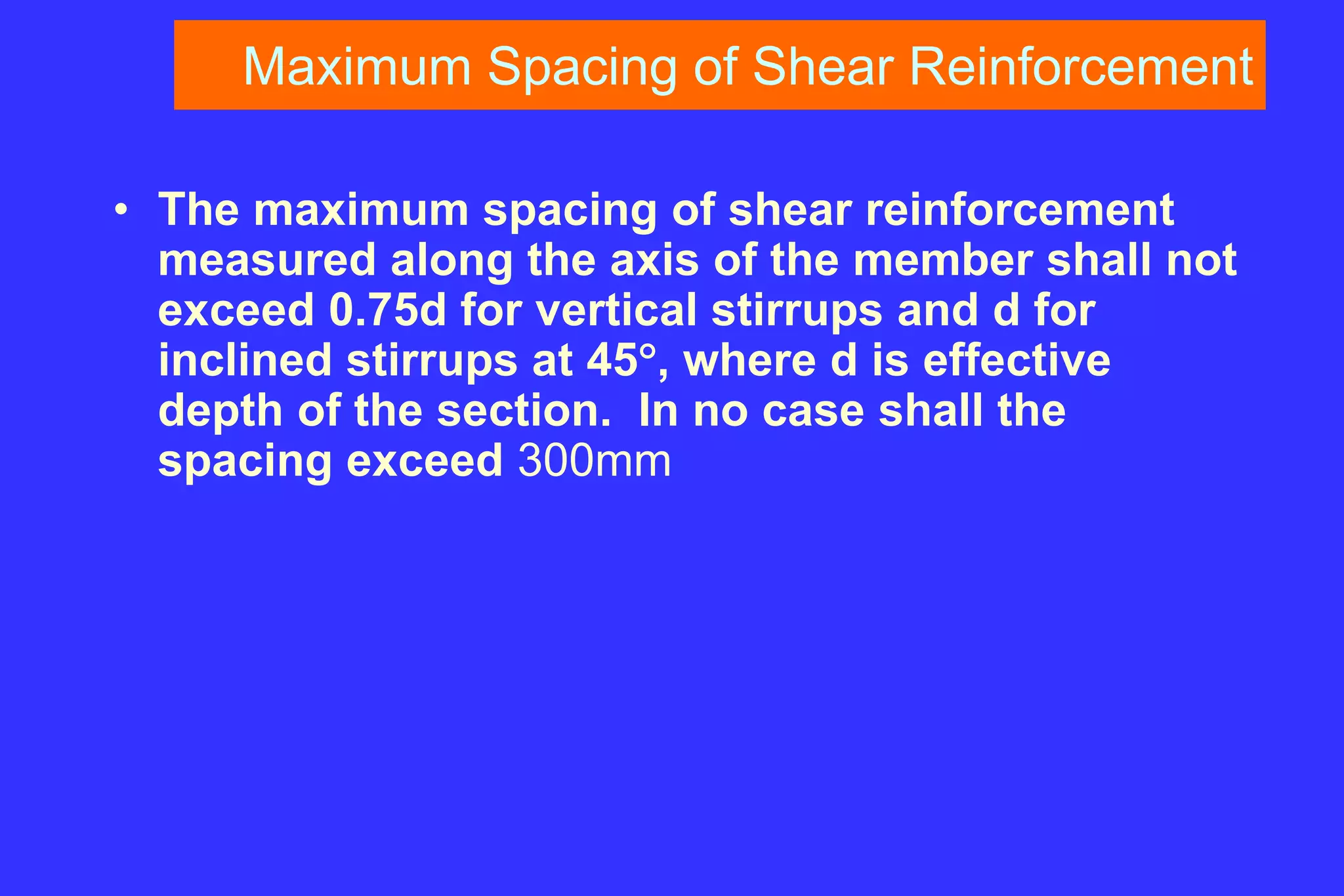
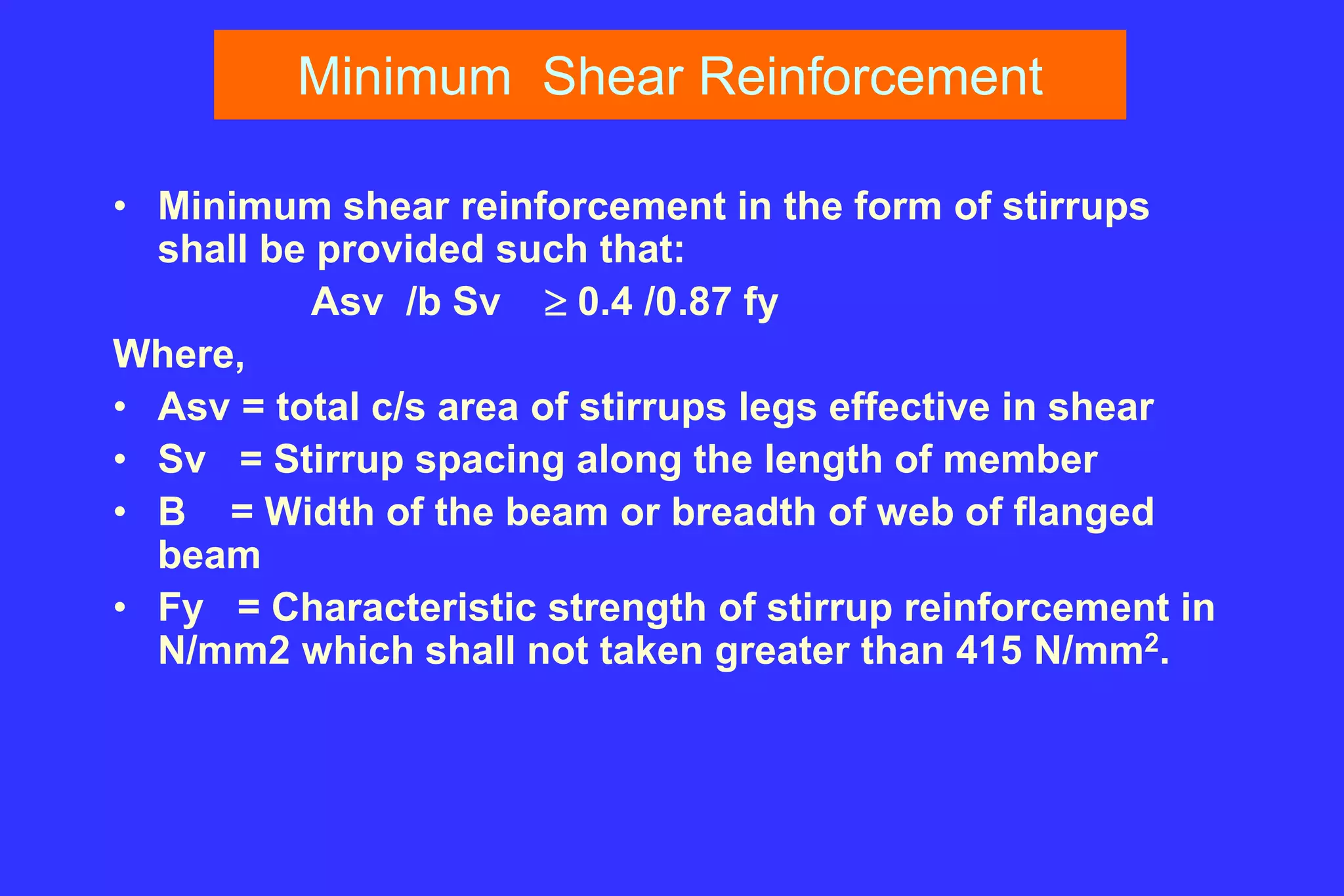
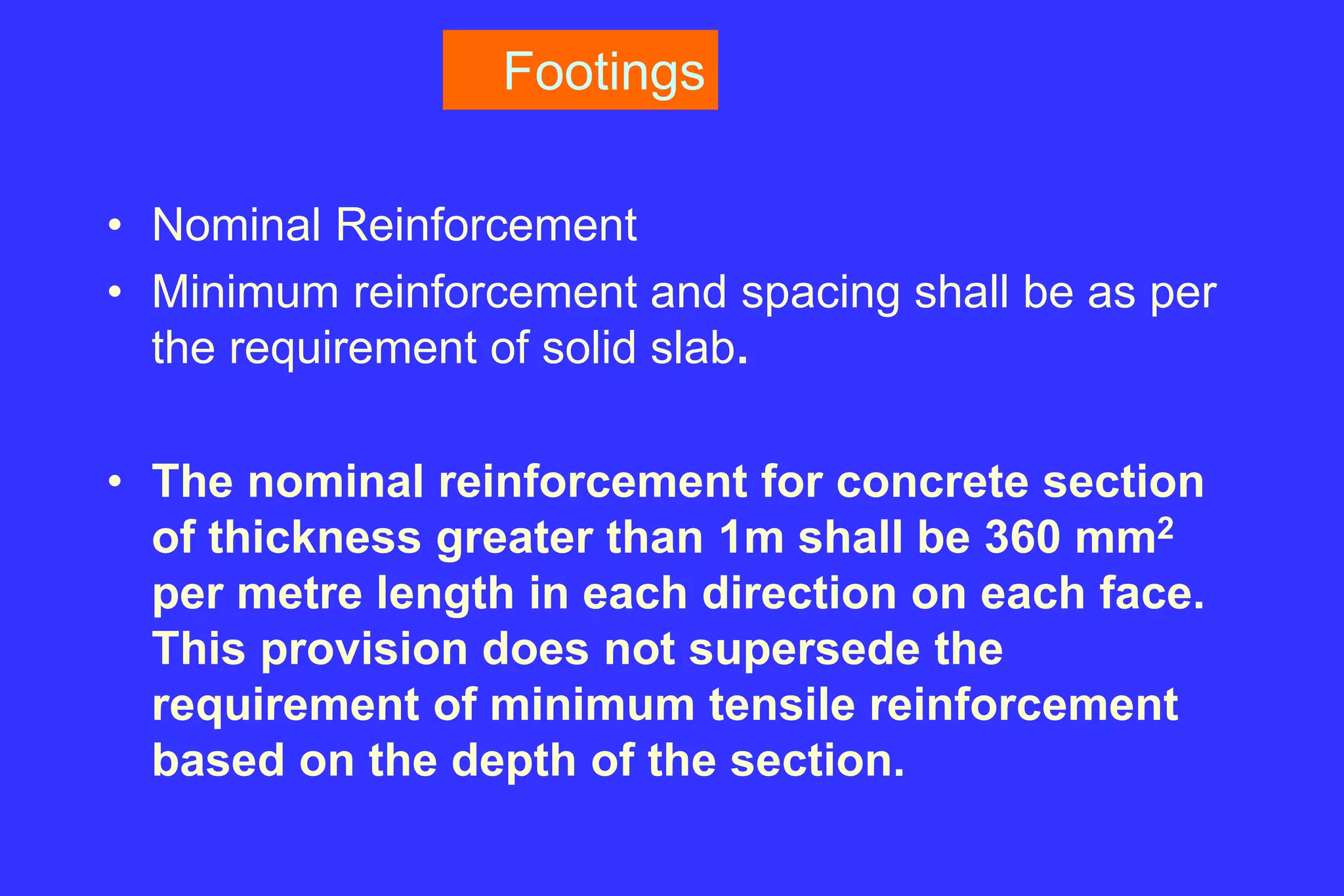
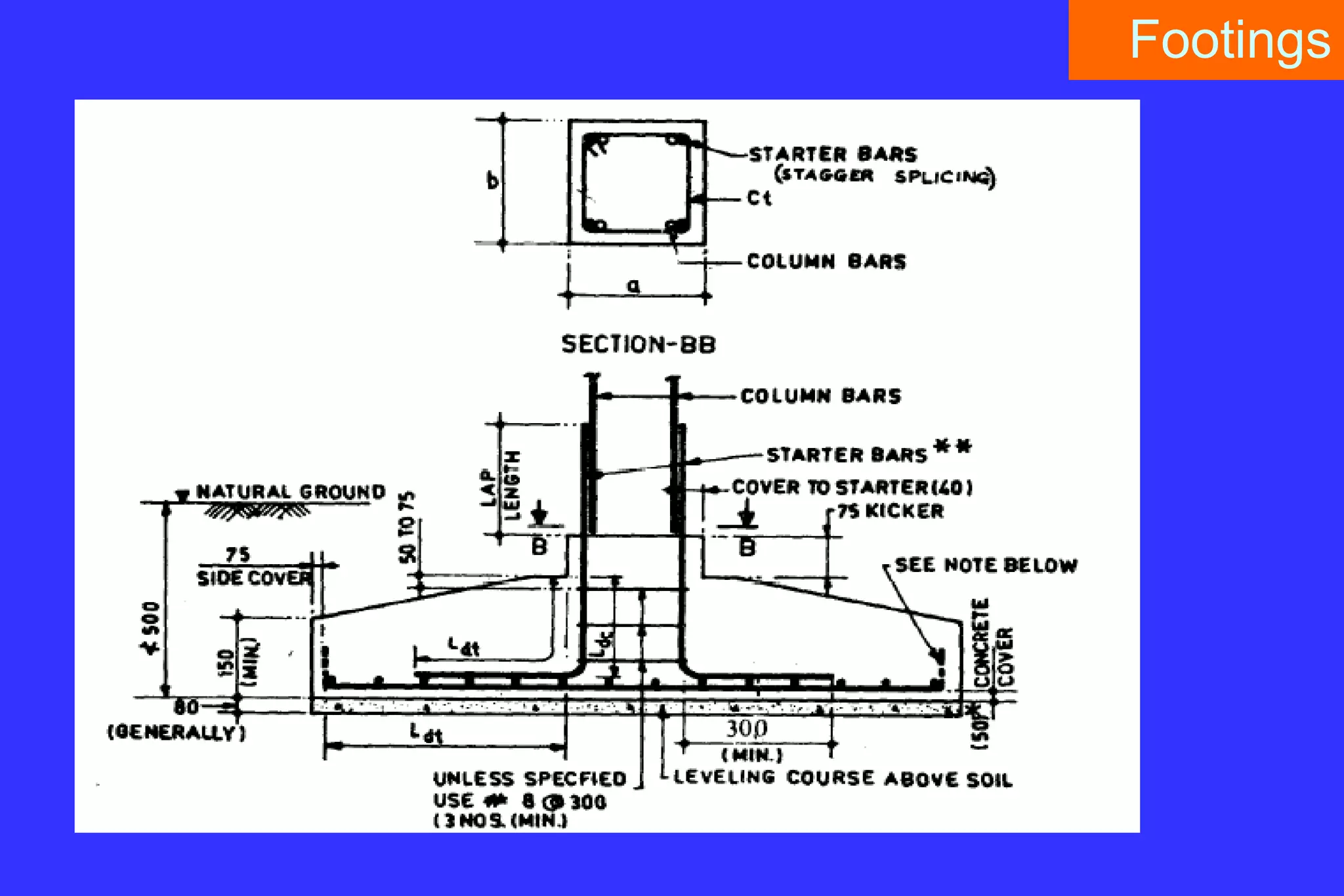
2. Key structural elements like beams, columns, slabs, shear walls, footings and their design.
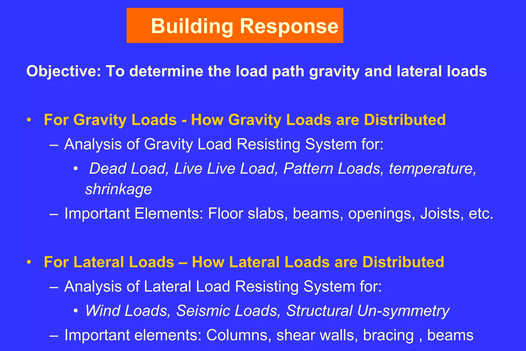
3. Concepts of the gravity load resisting system, lateral load resisting system and floor diaphragm.
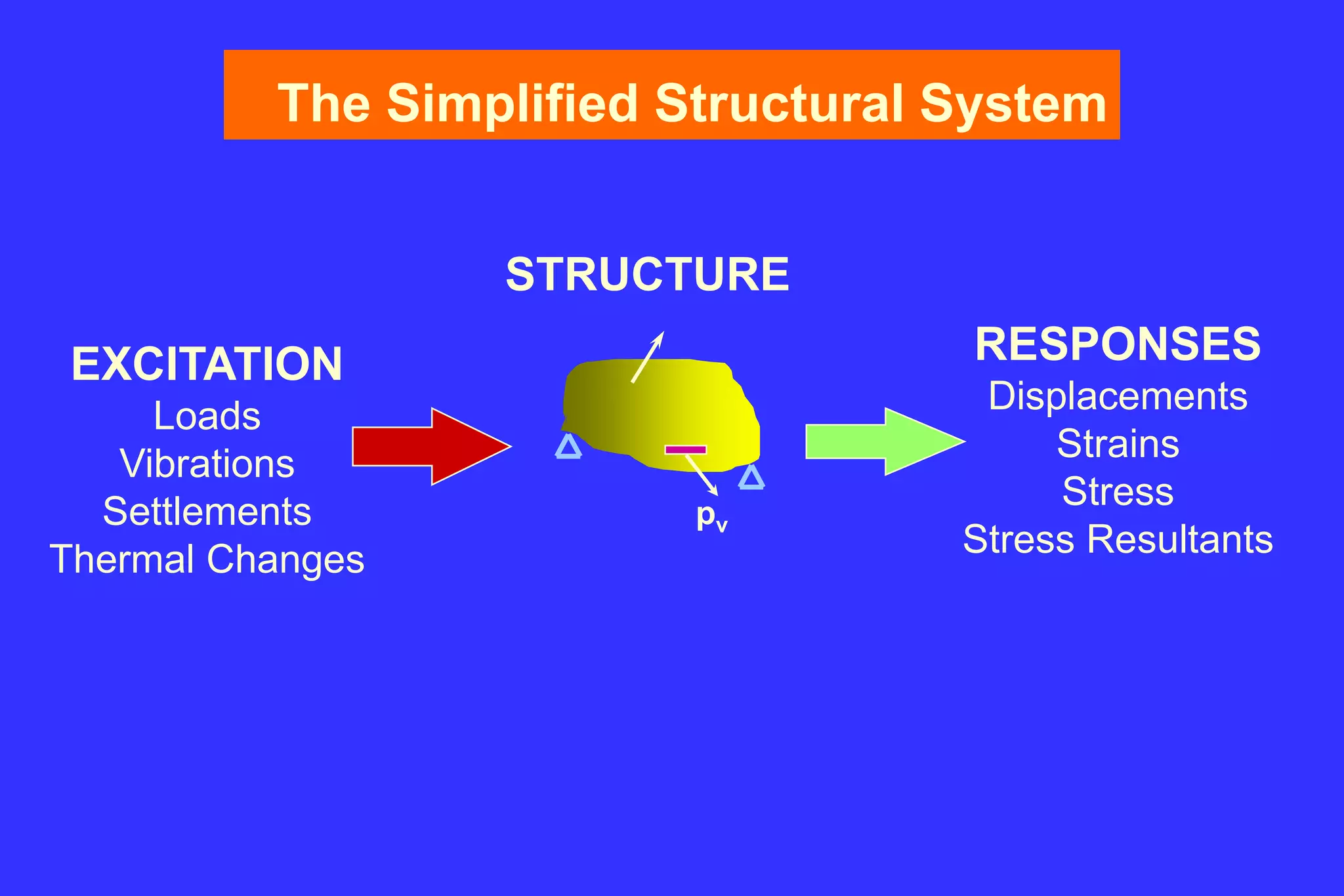
4. Methods of structural analysis including modeling approaches and consideration of loads and load combinations.
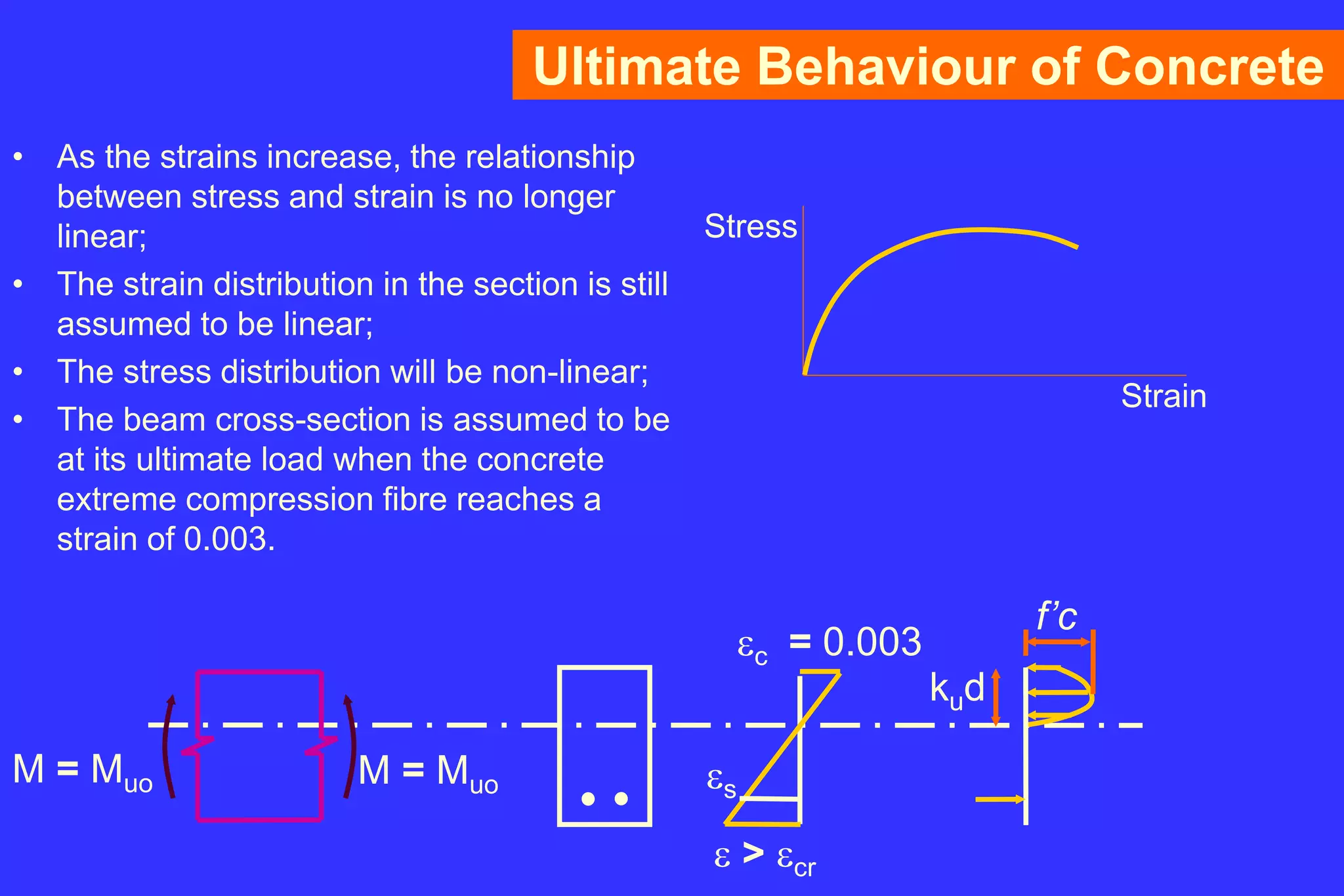
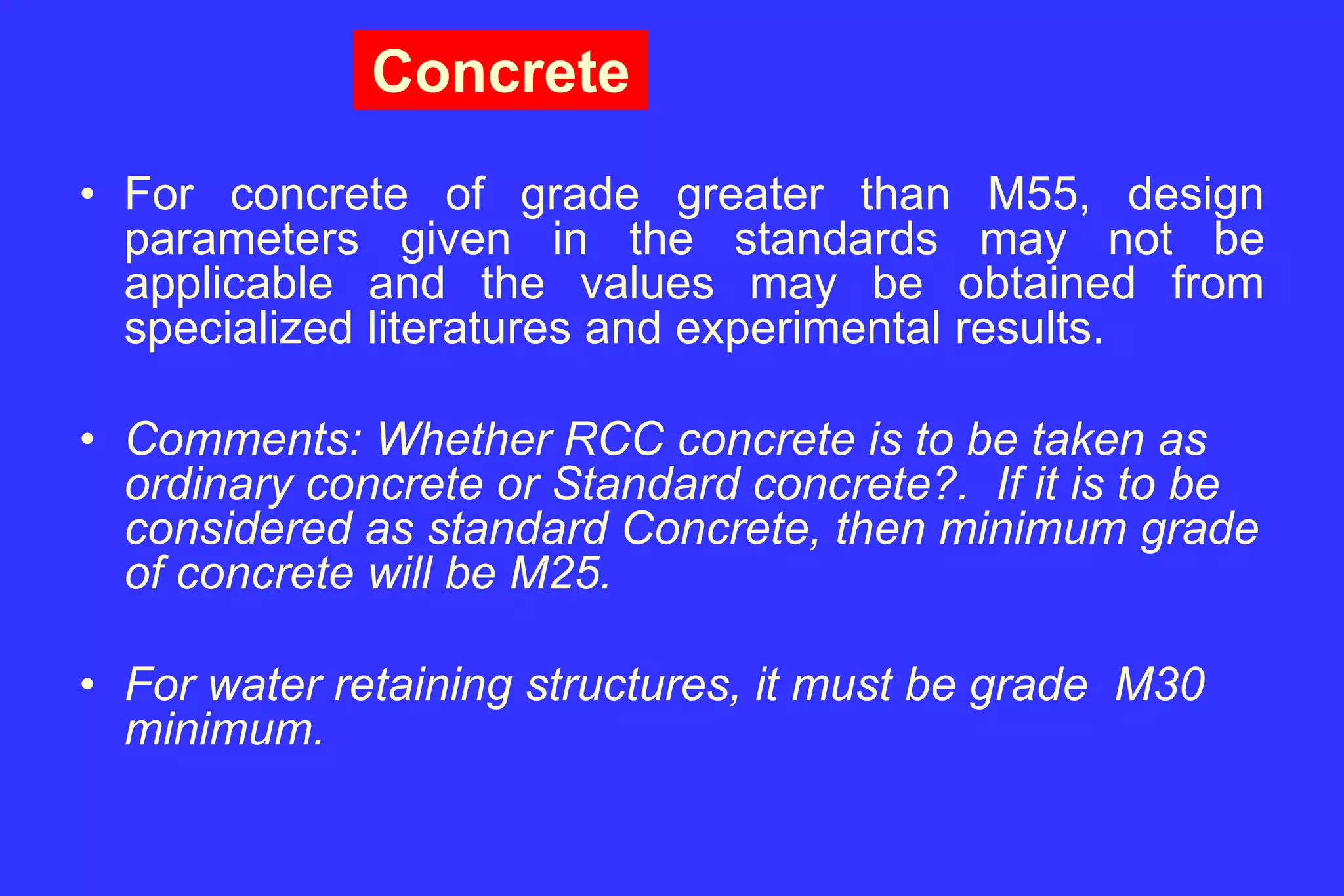
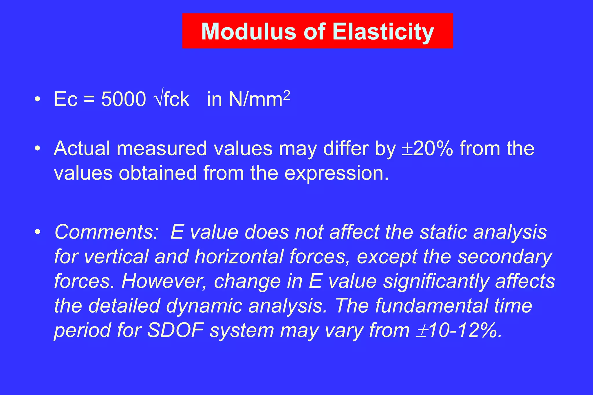
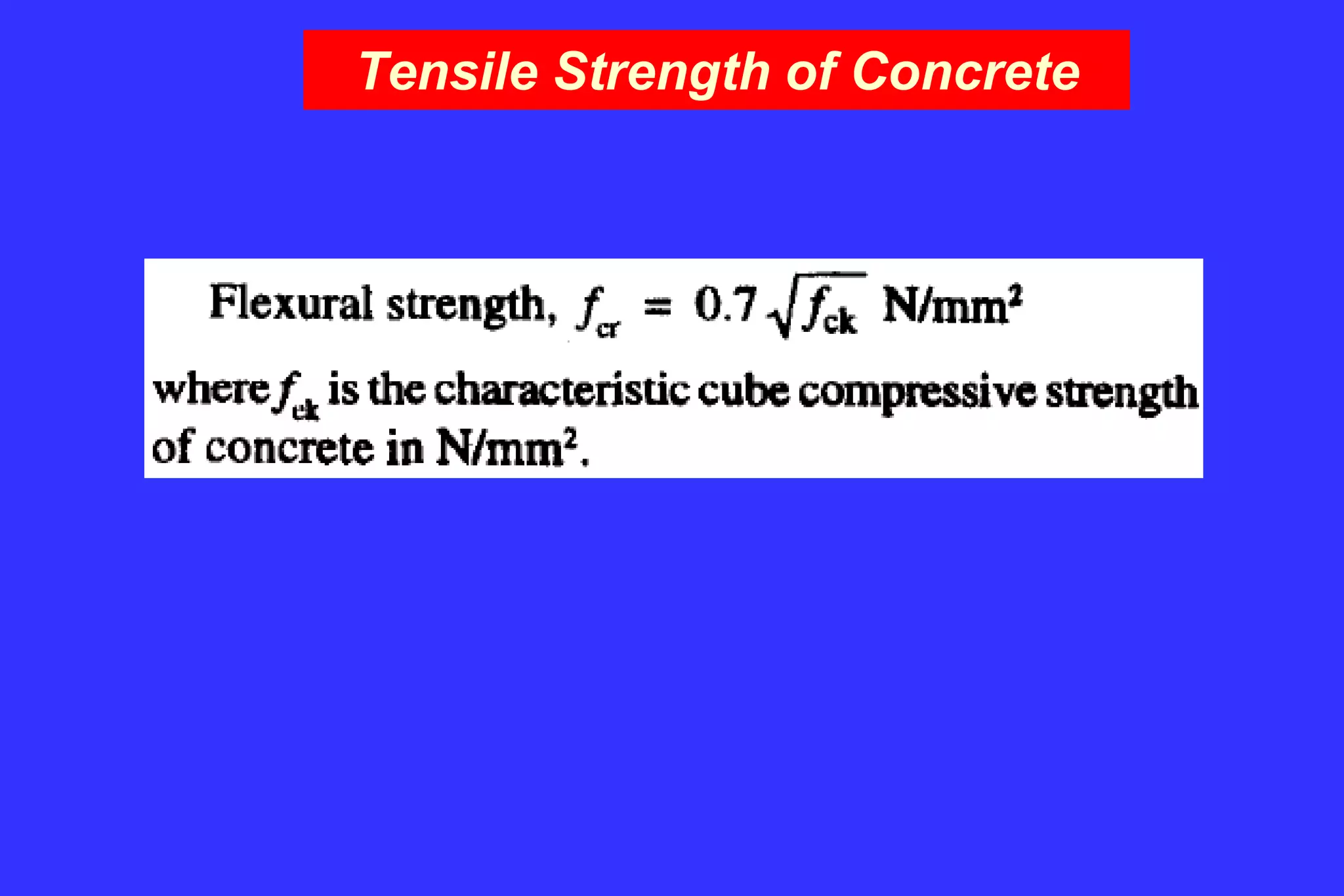
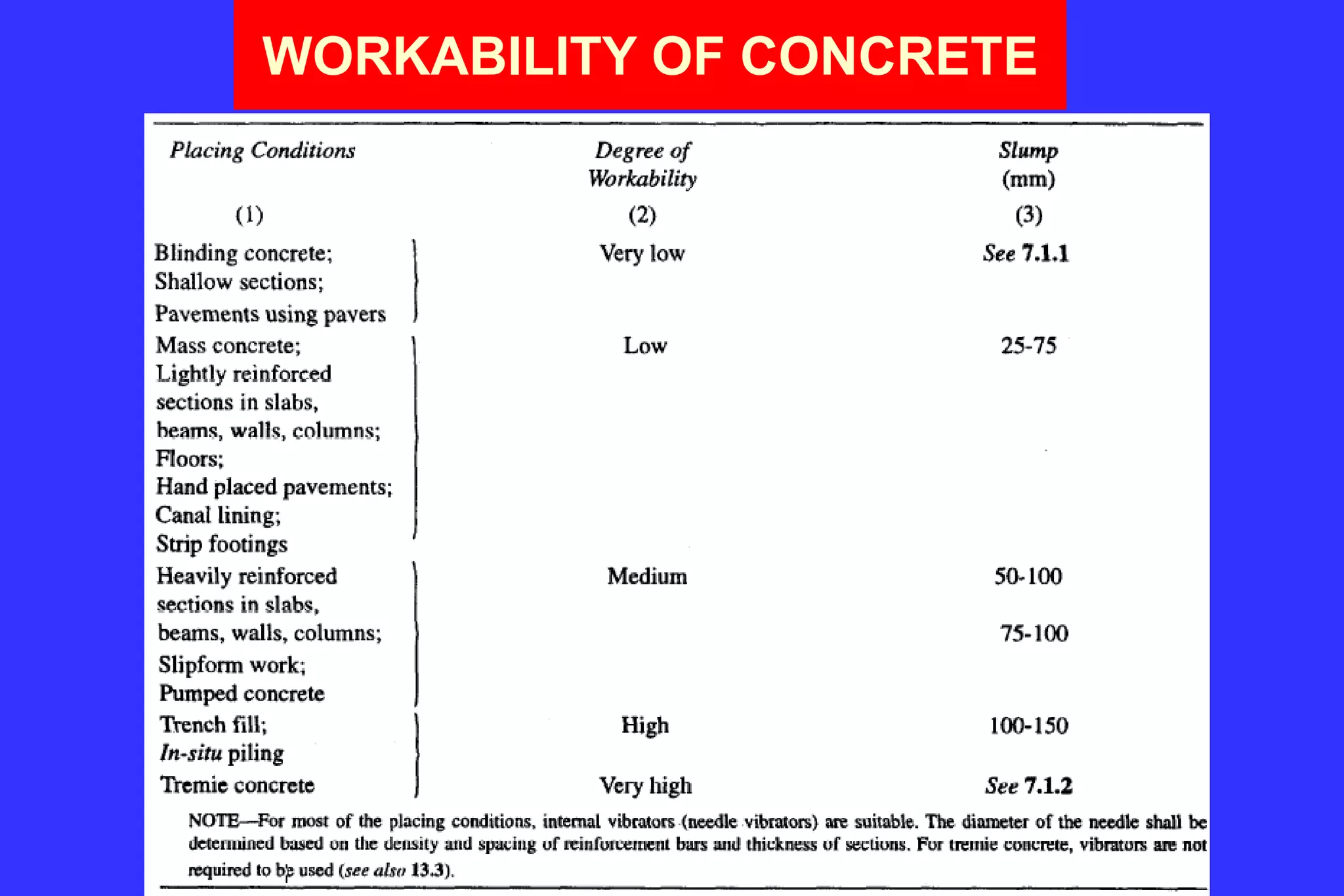
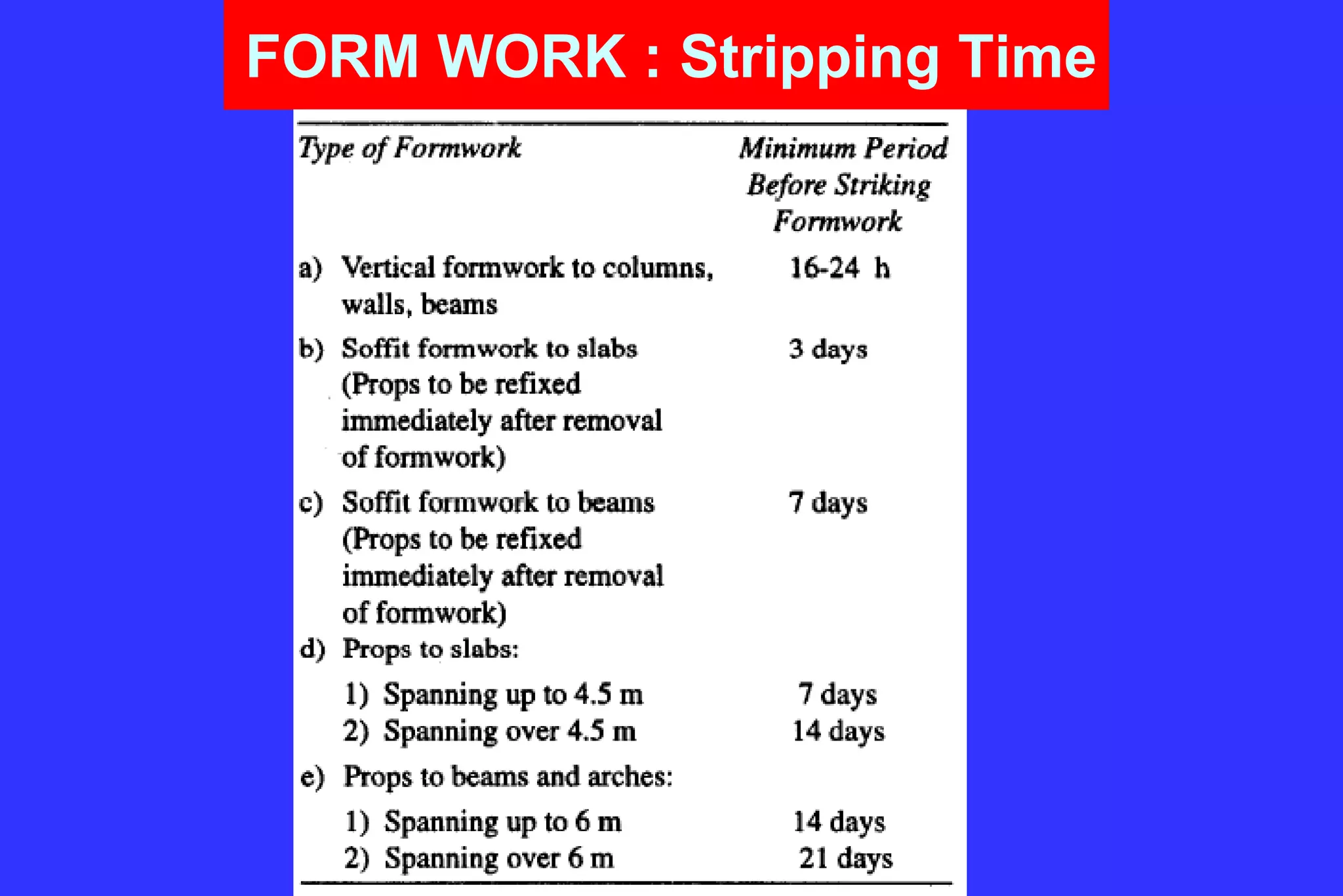
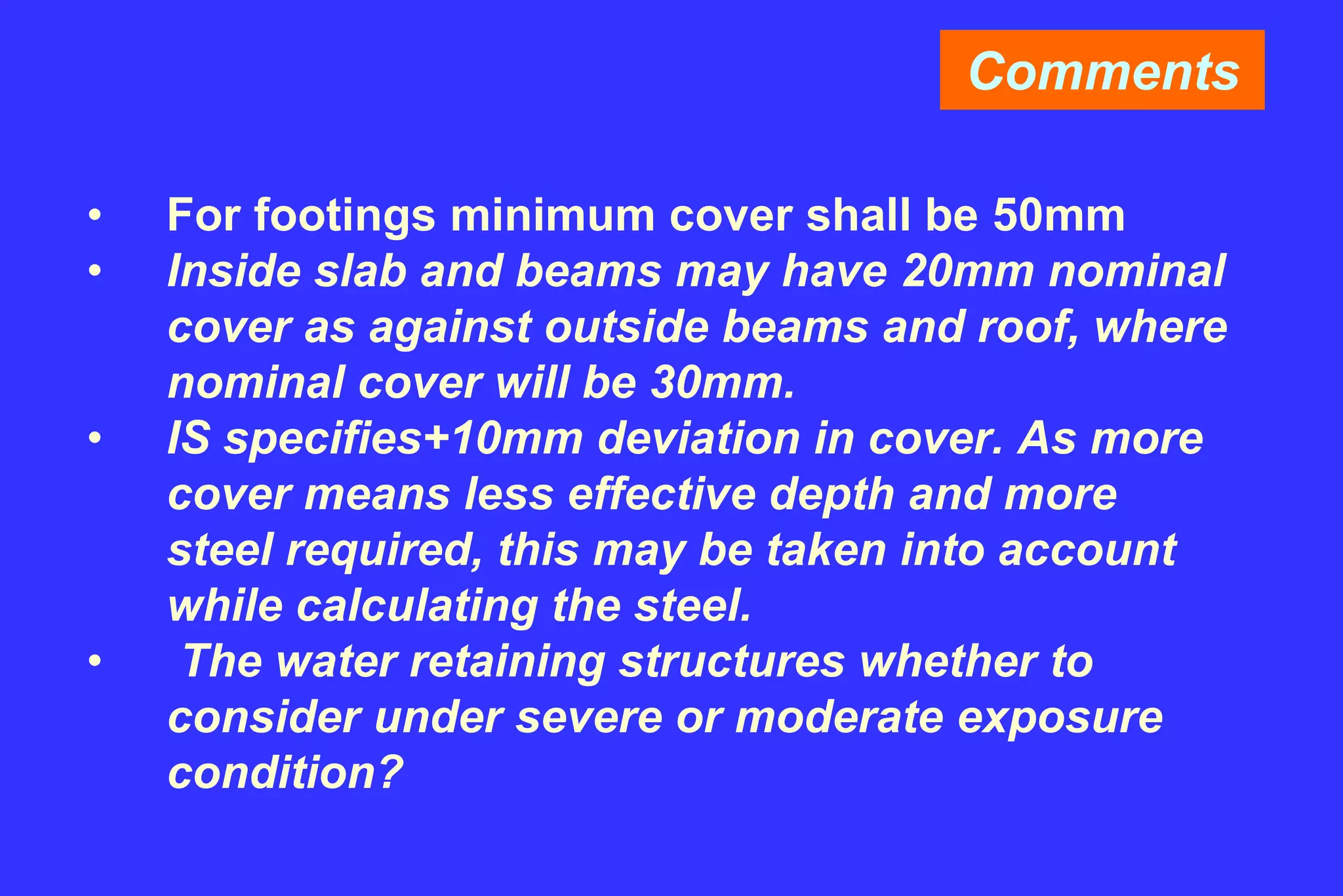
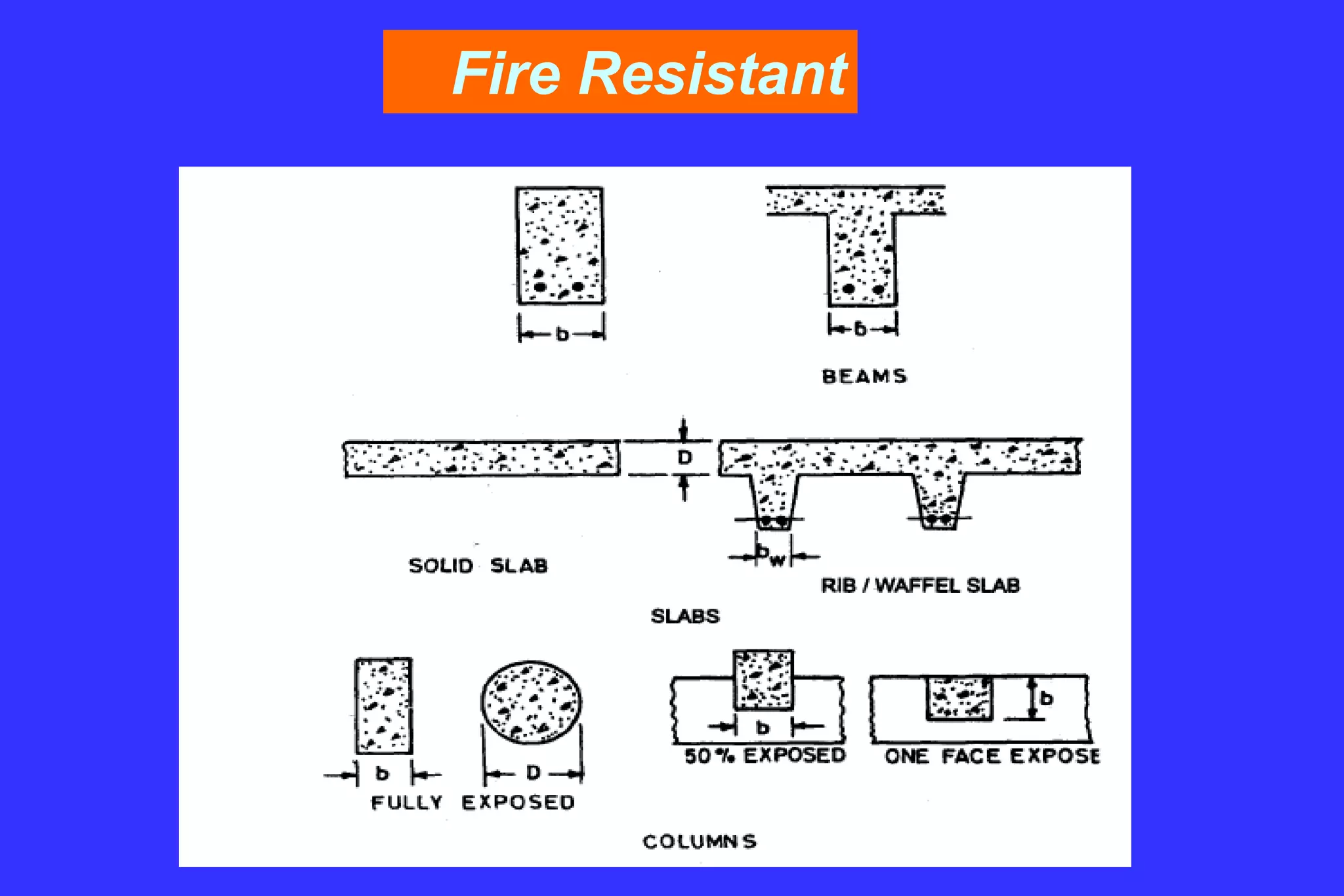
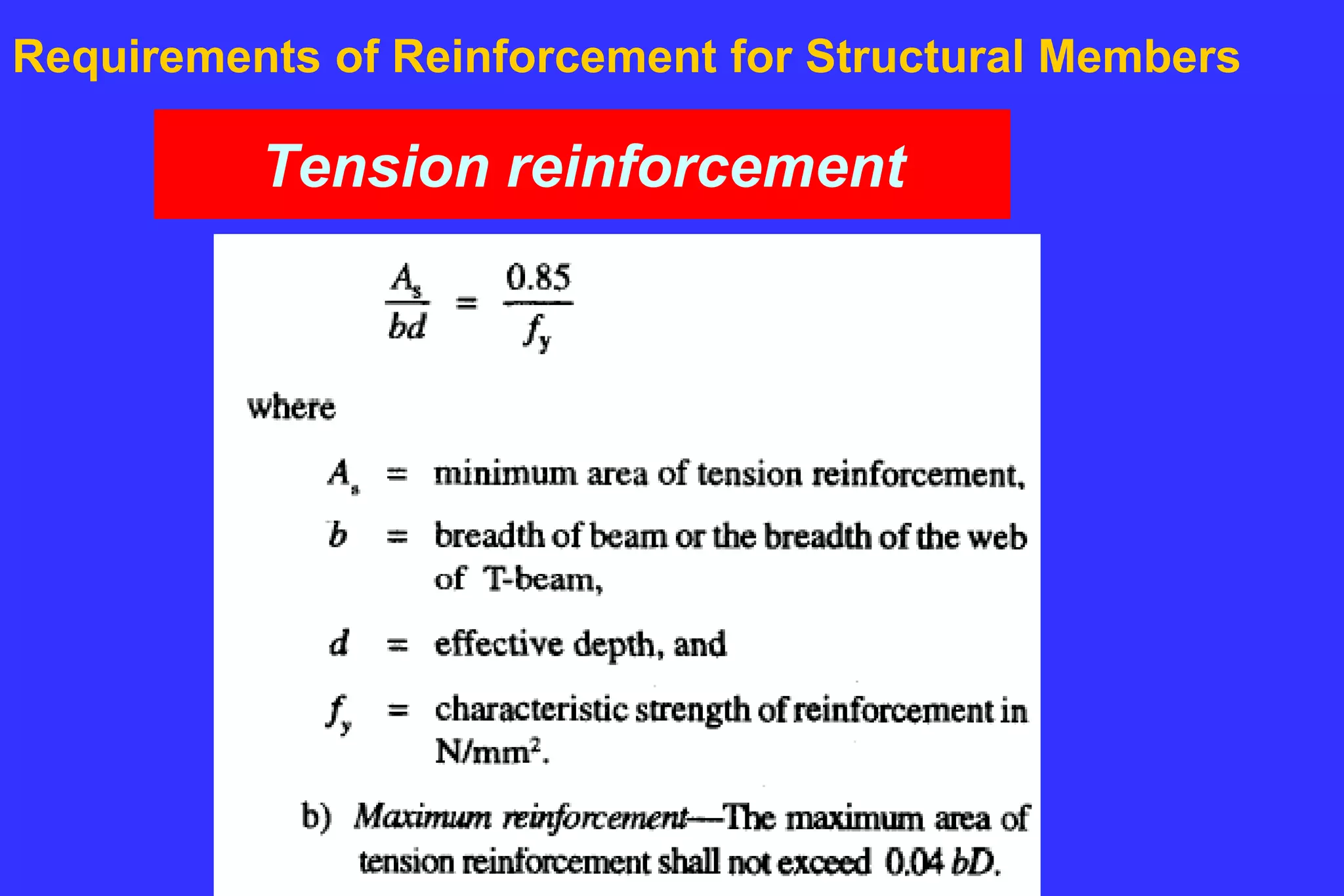
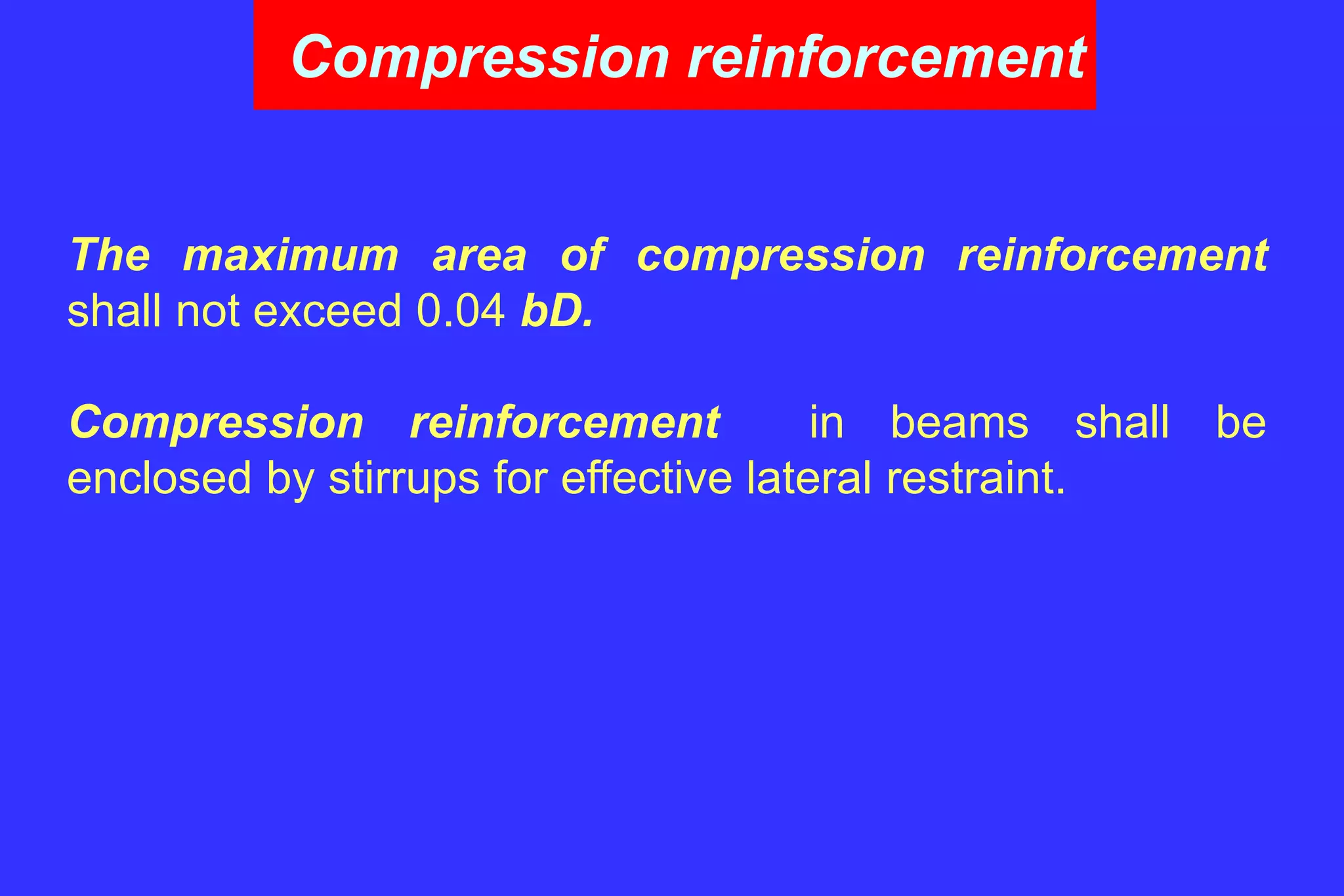
5. Design principles for concrete including properties, reinforcement, durability and mix proportioning.


![Example-1: Cont.
Calculation of Depth of Neutral axis : Nd
Pm = 0.003927x13.33 = 0.052347
A = 2(pm)+(pm)(pm) = 0.32777
N = A - (pm)
= 0.2754
Nd = 0.2754x160 = 44mm
Calculation of tensile stress in steel under service load: fst
fst = [M (d-Nd) / Icr ] m
Icr = b (Nd)^3 /3 + m Ast (d-nd)^2
= 141095470 mm^4
fst = 219 N/sqmm](https://image.slidesharecdn.com/reinforced-cement-concreteprof-aquib-230707144420-a7accc26/75/reinforced-cement-concrete_prof-aquib-ppt-101-2048.jpg)
![Example-1: Cont.
Calculation of Strain
e1 = Strain at the level considered, calculated ignoring the stiffening of
the concrete in the tension zone
= fst/Es [(D-Nd)/(d-nd)]
= 219/2e5 [(185-44)/(160-44)]
=0.001331
Calculation for Crackwidth
Cover Cmin = 20mm Spacing/2 = 125/2=62.5mm
acr = 20x20 + 62.5x62.5 = 65.623mm
b(h-x)(a-x)
em = e1 - -----------------
3 Es As (d-x)
=0.001331 – 1000(185-44)(185-44)/[3x2e5x628.32(160-44)]
= 0.00087638](https://image.slidesharecdn.com/reinforced-cement-concreteprof-aquib-230707144420-a7accc26/75/reinforced-cement-concrete_prof-aquib-ppt-102-2048.jpg)


![[BROCHURE] Italy Tour Project | @SlideON](https://cdn.slidesharecdn.com/ss_thumbnails/brochure8-251215152319-2805af68-thumbnail.jpg?width=640&height=640&fit=bounds)


