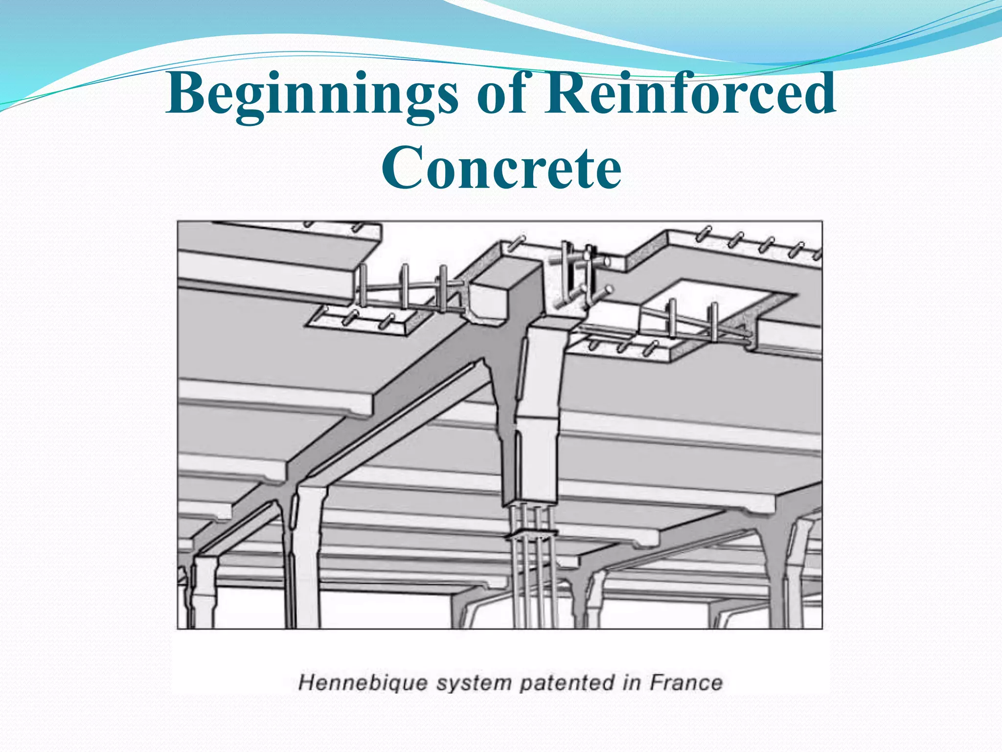
Amol Holani 111303020
Mayur Kulkarni 111307033
Pawan Mugal 111307039
Pranav Kulkarni 111305028
Prasad Shegokar 111303054
Sarthak Shirsat 111308062
Reinforced Cement Concrete(RCC)
 Reinforced Cement Concrete is a combination of
concrete and steel to build a structure instead of
using only concrete.
Brief History
 François Coignet was a French industrialist of the
nineteenth century, a pioneer in the development of
structural, prefabricated and reinforced concrete.
 In 1853 Coignet built the first iron reinforced concrete
structure, a four story house in Paris.
 Ernest L. Ransome, was an innovator of the reinforced
concrete techniques in the end of the 19th century
Uses of RCC
 It is used in the construction of Columns, Beams,
Footings, Slabs etc.
 It is used in storage structures like Dams, Water Tanks,
Tunnels etc.
 It is used to build heavy structures like Bridges, Walls,
Towers, Under water structures.
 It is used in tall structures and sky scrapers.
Why it is essential?
 High relative strength
 High toleration of tensile strain
 Good bond to the concrete, irrespective of pH,
moisture, and similar factors
 Thermal compatibility, not causing unacceptable
stresses in response to changing temperatures.
 Durability in the concrete environment, irrespective of
corrosion or sustained stress for example.
Merits of Reinforced Concrete
1. Good Binding Between Steel and Concrete
there is a very good development of bond between steel and concrete.
2. Stable Structure
Concrete is strong in compression but week in tension and steel as
strong in tension so their combination give a strong stable structure.
3. Less Chances of Buckling
Concrete members are not slim like steel members so chances of
buckling are much less.
4. Aesthetics
concrete structures are aesthetically good and cladding is not required
5. Lesser Chances of Rusting
steel reinforcement is enclosed in concrete so chances of
rusting are reduced.
3/24/2015 6:24:23 PM 6
Short Reinforced Concrete Compression
Members
 Short - slenderness does not need to be considered –
column will not buckle
 Only axial load
L
Cross-sectional Areas:
As = Area of steel
Ac = Area of concrete
Ag = Total area
Fs = stress in steel
Fc = stress in concrete
From Equilibrium:
P = Acfc + Asfs
P
L
P
If bond is maintained εs = εc
Reinforced Concrete
Mechanism of Load
Transfer
Load
Roof Surface
Roof Slab
Beams
Column
Foundation
Sub Soil
3/24/2015 6:24:23 PM 8
Function of structure is
to transfer all the loads
safely to ground.
A particular structural
member transfers load
to other structural
member.
Design Loads
 Dead Load
“The loads which do not change their magnitude and
position w.r.t. time within the life of structure”
Dead load mainly consist of superimposed loads and self load of
structure.
 Self Load
It is the load of structural member due to its own weight.
 Superimposed Load
It is the load supported by a structural member. For
instance self weight of column is self load and load of
beam and slab over it is superimposed load.
3/24/2015 6:24:23 PM 9
Design Loads (contd…)
 Live Load
“Live loads consist chiefly of occupancy loads in buildings
and traffic loads on bridges”
 They may be either fully or partially in place or not
present at all, and may also change in location.
 Their magnitude and distribution at any given time are
uncertain, and even their maximum intensities throughout
the life time of the structure are not known with precision.
 The minimum live loads for which the floor and roof of a
building should be designed are usually specified in the
building codes that governs at the site construction.
3/24/2015 6:24:23 PM 10
Objectives of Designer
There are two main objectives
1. Safety
2. Economy
Safety
The structure should be safe enough to carry all the applied
throughout the life.
Economy
Structures should be economical. Lighter structures are
more economical.
Economy α 1/self weight (More valid for Steel Structures)
In concrete Structures overall cost of construction decides the
economy, not just the self weight.
3/24/2015 6:24:23 PM 11
Load Combinations
To combine various loads in such a way to get a critical situation.
Load Factor = Factor by which a load is to be increased x probability
of occurrence
1. 1.2D + 1.6L
2. 1.4D
3. 1.2D + 1.6L + 0.5Lr
4. 1.2D + 1.6Lr + (1.0L or 0.8W)
Where
D = Dead load
L = Live load on intermediate floors
Lr = Live load on roof
W = Wind Load
3/24/2015 6:24:23 PM 12
Shrinkage
“Shrinkage is reduction in volume of concrete due to loss
of water”
Coefficient of shrinkage varies with time. Coefficient of shortening is:
 0.00025 at 28 days
 0.00035 at 3 months
 0.0005 at 12 months
Shrinkage = Shrinkage coefficient x Length
Excessive shrinkage can be avoided by proper curing
during first 28 days because half of the total shrinkage
takes place during this period
3/24/2015 6:24:23 PM 13
Creep
“creep is the slow
deformation of material
over considerable lengths of
time at constant stress or
load”
Creep deformations for a given
concrete are practically
proportional to the magnitude of
the applied stress; at any given
stress, high strength concrete
show less creep than lower
strength concrete.
Compressive
strength
Specific
Creep
(MPa) 10-6 per MPa
20 145
30 116
40 80
55 58
3/24/2015 6:24:23 PM 14
Plain & Reinforced Concrete
Creep (contd…)
How to calculate shortenings due to creep?
Consider a column of 3m which is under sustained load for
several years.
Compressive strength, fc’ = 30 MPa
Sustained stress due to load = 10 MPa
Specific creep for 28 MPa fc’ = 116 x 10-6 per MPa
Creep Strain = 10 x 116 x 10-6 = 116 x 10-5
Shortening due to creep = 3000 x 116 x 10-5
= 3.48 mm
3/24/2015 6:24:23 PM 15
Strength measurement
Specified Compressive Strength Concrete, fc’
“28 days cylinder strength of concrete”
 The cylinder has 150mm dia and 300mm length.
 According to ASTM standards at least two cylinders
should be tested and their average is to be taken.
ACI 5.1.1: for concrete designed and constructed in
accordance with ACI code, fc’ shall not be less than 17 Mpa
(2500 psi)
3/24/2015 6:24:23 PM 16
Plain & Reinforced Concrete-1
3/24/2015 6:24:23 PM 17
Concrete Cylinder Concrete Cube
Beginnings of Reinforced
Concrete
CAUSES OF FAILURES IN RCC BUILDING
 EARTHQUAKE
 CORROSION
When the earthquake forces exceed the design
parameters, the alternating forces of the earthquake
first break the concrete on one side of the column and
subsequently on the other side.
Building A
Building B
Building A :- has thick and stiff floors and
slender supporting columns.
During a earthquake, the whole building will pancake.
the bottom columns receive the largest forces and
bend; walls crack
Building B :- has a ductile floor design.
During Earthquake, Floors will be waving and
cracking, but the building would not collapse.
CORROSION
CAUSES OF CORROSION
 Moisture
 Oxygen diffusion
 Temperature
 Humidity
How to avoid corrosion?
Careful detailing to protect from water
Use stainless steel
Protect steel with galvanizing (zinc coating) or
other protective coating
Corrosion of Steel
Every 90 seconds, across the world, one ton
of steel turns to rust; of every two tons of
steel made, one is to replace rust.
 Most concrete used for construction is a combination of
concrete and reinforcement that is called reinforced
concrete.
 Steel is the most common material used as reinforcement,
but other materials such as fiber-reinforced polymer (FRP)
are also used
Reinforcement in a concrete column
REINFORCEMENT USED IN RCC BUILDING
 Fiber reinforcement:
Fiber-reinforced concrete (FRC) is concrete with the addition of discrete
reinforcing fibers made of steel, glass, synthetic(nylon, polyester, and
polypropylene), and natural fiber materials.
 Synthetic fibers can be delivered to the mixing system in preweighed,
degradable bags that break down during the mixing cycle. Steel fibers are
introduced to the rotating mixer via conveyor belt, either at the same time as
the coarse aggregate or on their own after all the conventional ingredients
have been added.
1. The major applications of FRC are slab-on-grade construction, precast
concrete, and shotcrete.
2. Some examples of slab-on-grade construction are airport runways,
residential, commercial, and industrial floor slabs, and hydraulic
structures
3. Fiber- reinforced shotcrete is used for rock slope stabilization, tunnel
liners, hydraulic structures, and maintenance of existing concrete.
4. FRC is also used in repair applications, such as repair of bridge decks,
piers, and parapets.
 Steel reinforcement:
Steel reinforcement is available in the form of plain steel bars,
deformed steel bars, cold-drawn wire, welded wire fabric, and
deformed welded wire fabric.
1. Deformed steel bars:—Deformed bars are round steelbars with lugs,
or deformations, rolled into the surface of the bar during
manufacturing
2. Threaded steel bars:—Threaded steel bars are made by several
manufacturers in different grades They are used as an alternative to
lapping standard deformed bars when long bar lengthsare required
3.Welded wire fabric:—Welded wire fabric reinforcement also known as
welded wire reinforcement is a square or rectangular mesh of wires.
Typical deformed reinforcing bar
Welded wire reinforcement sheets
TYPES OF CONCRETE
1.Prestressed concrete:
 Prestressed concrete is structural concrete in which internal stresses
have been introduced to reduce potential tensile stresses in the
concrete resulting from loads.
 Applications
a. To resist internal pressures in circular structures like tank, pipe
b. To limit cracking in bridge decks and slabs-on-grade.
c. To improve capacity of columns and piles.
d. To reduce long-term deflections.
2.Plain concrete:
 Plain concrete is structural concrete without reinforcement
 It is sometimes used in slabs-on grade ,pavement, basement walls,
small foundations, and curb-and-gutter.
3.Pretensioned concrete:
 Pretensioning is usually performed in a factory (or
precasting yard). The tendons are held in place and
tensioned against the ends of the casting bed before the
concrete is placed.
 Advantages of pretensioned concrete are that it
tendons are bonded to the concrete over their entire
length.
4.Post-tensioned concrete:
 Post-tensioning is usually performed at the job site. Post-
tensioning tendons are usually internal but can be external.
 Some of the advantages of post-tensioning are that it does
not require the large temporary anchorages required for
pretensioning,
 It allows for larger members than are possible in a
precasting plant.
Plain & Reinforced Concrete
Reinforced Cement Concrete (RCC) contd..
Mix Proportion
Cement : Sand : Crush
1 : 1.5 : 3
1 : 2 : 4
1 : 4 : 8
Water Cement Ratio (W/C)
W/C = 0.5 – 0.6
For a mix proportion of 1:2:4 and W/C = 0.5, if cement is 50 kg
Sand = 2 x 50 = 100 Kg
Crush = 4 x 50 = 200 Kg Batching By Weight
Water = 50 x 0.5 = 25 Kg
3/24/2015 6:24:23 PM 32
Structural Member of RCC
 Slabs
 Beams
 Columns
 Foundation
Slabs
 It is better to provide a max spacing of 200mm(8”) for
main bars and 250mm(10”) in order to control the
crack width and spacing.
 A min. of 0.24% shall be used for the roof slabs since it
is subjected to higher temperature. Variations than the
floor slabs. This is required to take care of temp.
differences.
 It is advisable to not to use 6mm bars as main bars as
this size available in the local market is of inferior
not only with respect to size but also the quality since
like TATA and SAIL are not producing this size of bar.
Beams
 A min. of 0.2% is to be provided for the compression bars
in order to take care of the deflection.
 The stirrups shall be minimum size of 8mm in the case of
lateral load resistance .
 The hooks shall be bent to 135 degree.
Columns
 Minimum cross-sectional dimension for a
Column.
 Longitudinal Reinforcement
 Transverse reinforcement
 Helical Reinforcement
Foundation
 Minimum size of foundation for a single storey of
G+1 building, where soil safe bearing capacity is 30
tonnes per square meter, and the oncoming load on
the column does not exceed 30 tonnes.
 Reinforcing bar details
Foundation
 Minimum size of foundation for a single storey of
G+1 building, where soil safe bearing capacity is 30
tonnes per square meter, and the oncoming load on
the column does not exceed 30 tonnes.
 Reinforcing bar details
 Arrangement of reinforcement in various
structural members :
 R.C.C. is used as a structural element, the common
structural elements in a building where
 R.C.C. is used are:
 (a) Footings (b) Columns
 (c) Beams and lintels (d) roofs and slabs.
1) Footings :
In rectangular footing the reinforcement parallel to the long
direction shall be distributed uniformly across the width of
the footing. In short direction, since the support provided to
the Footing by the column is concentrated near the middle,
the moment per unit length is largest i.e., the curvature of
the footing is sharpest immediately under the column and
decreases in the long direction with the increasing distance
from the column. For this reason larger steel area is needed
in the central portion and is determined in accordance with
the equation given below.
 2) Columns :
 The main reinforcement in columns in longitudional
, parallel to the direction to the direction of the load
and consists of bars arranged in square, rectangular or
spherical shape.
 Main steel is provided to resist the compression load
along with the concrete.
 The bar shall not be less than 12mm in diameter
 Nominal max. Size of coarse aggregte is5mm.
 The no of bars in columns are varies from 10, 12, 14, 16
with varying diameter.
3) Beams :
 Generally a beam consists of following types of
reinforcements :
 Longitudinal reinforcement .
 Shear reinforcements.
 Side face reinforcement in the web of the beam is provided
when the depth of the web in a beam exceeds 750 mm.
 Arrangements of bars in a beam should confirm to the
requirements of clause given in 8.1and 8.2of SP34.Bars of
size 6,8,10,12,16,20,25,32,50 mm are available in market.
Thickness of the slab is decided based on span to depth ratio . Min
reinforcement is 0.12% for HYSD bars and 0.15% for mild steel bars. The
diameter of bar generally used in slabs are: 6 mm, 8 mm, 10 mm, 12 mm
and 16 mm.
The maximum diameter of bar used in slab should not exceed 1/8 of the
total thickness of slab. Maximum spacing of main bar is restricted to 3
times effective depth . For distribution bars the maximum spacing is
specified as 5 times the effective depth .
4) Slabs :
Minimum clear cover to reinforcements in slab depends
on the durability criteria . Generally 15 mm to 20 mm
cover is provided for the main reinforcements.
Torsion reinforcement shall be provided at any corner
where the slab is simply supported on both edges
meeting at that corner.It shall consist of top and bottom
reinforcement, each with layer of bars placed parallel to
the sides of the slab and extending from the edges a
minimum distance of one fifth of the shorter span.
Details of RCC Building

Details of RCC Building

  • 1.
    Amol Holani 111303020 MayurKulkarni 111307033 Pawan Mugal 111307039 Pranav Kulkarni 111305028 Prasad Shegokar 111303054 Sarthak Shirsat 111308062
  • 2.
    Reinforced Cement Concrete(RCC) Reinforced Cement Concrete is a combination of concrete and steel to build a structure instead of using only concrete.
  • 3.
    Brief History  FrançoisCoignet was a French industrialist of the nineteenth century, a pioneer in the development of structural, prefabricated and reinforced concrete.  In 1853 Coignet built the first iron reinforced concrete structure, a four story house in Paris.  Ernest L. Ransome, was an innovator of the reinforced concrete techniques in the end of the 19th century
  • 4.
    Uses of RCC It is used in the construction of Columns, Beams, Footings, Slabs etc.  It is used in storage structures like Dams, Water Tanks, Tunnels etc.  It is used to build heavy structures like Bridges, Walls, Towers, Under water structures.  It is used in tall structures and sky scrapers.
  • 5.
    Why it isessential?  High relative strength  High toleration of tensile strain  Good bond to the concrete, irrespective of pH, moisture, and similar factors  Thermal compatibility, not causing unacceptable stresses in response to changing temperatures.  Durability in the concrete environment, irrespective of corrosion or sustained stress for example.
  • 6.
    Merits of ReinforcedConcrete 1. Good Binding Between Steel and Concrete there is a very good development of bond between steel and concrete. 2. Stable Structure Concrete is strong in compression but week in tension and steel as strong in tension so their combination give a strong stable structure. 3. Less Chances of Buckling Concrete members are not slim like steel members so chances of buckling are much less. 4. Aesthetics concrete structures are aesthetically good and cladding is not required 5. Lesser Chances of Rusting steel reinforcement is enclosed in concrete so chances of rusting are reduced. 3/24/2015 6:24:23 PM 6
  • 7.
    Short Reinforced ConcreteCompression Members  Short - slenderness does not need to be considered – column will not buckle  Only axial load L Cross-sectional Areas: As = Area of steel Ac = Area of concrete Ag = Total area Fs = stress in steel Fc = stress in concrete From Equilibrium: P = Acfc + Asfs P L P If bond is maintained εs = εc
  • 8.
    Reinforced Concrete Mechanism ofLoad Transfer Load Roof Surface Roof Slab Beams Column Foundation Sub Soil 3/24/2015 6:24:23 PM 8 Function of structure is to transfer all the loads safely to ground. A particular structural member transfers load to other structural member.
  • 9.
    Design Loads  DeadLoad “The loads which do not change their magnitude and position w.r.t. time within the life of structure” Dead load mainly consist of superimposed loads and self load of structure.  Self Load It is the load of structural member due to its own weight.  Superimposed Load It is the load supported by a structural member. For instance self weight of column is self load and load of beam and slab over it is superimposed load. 3/24/2015 6:24:23 PM 9
  • 10.
    Design Loads (contd…) Live Load “Live loads consist chiefly of occupancy loads in buildings and traffic loads on bridges”  They may be either fully or partially in place or not present at all, and may also change in location.  Their magnitude and distribution at any given time are uncertain, and even their maximum intensities throughout the life time of the structure are not known with precision.  The minimum live loads for which the floor and roof of a building should be designed are usually specified in the building codes that governs at the site construction. 3/24/2015 6:24:23 PM 10
  • 11.
    Objectives of Designer Thereare two main objectives 1. Safety 2. Economy Safety The structure should be safe enough to carry all the applied throughout the life. Economy Structures should be economical. Lighter structures are more economical. Economy α 1/self weight (More valid for Steel Structures) In concrete Structures overall cost of construction decides the economy, not just the self weight. 3/24/2015 6:24:23 PM 11
  • 12.
    Load Combinations To combinevarious loads in such a way to get a critical situation. Load Factor = Factor by which a load is to be increased x probability of occurrence 1. 1.2D + 1.6L 2. 1.4D 3. 1.2D + 1.6L + 0.5Lr 4. 1.2D + 1.6Lr + (1.0L or 0.8W) Where D = Dead load L = Live load on intermediate floors Lr = Live load on roof W = Wind Load 3/24/2015 6:24:23 PM 12
  • 13.
    Shrinkage “Shrinkage is reductionin volume of concrete due to loss of water” Coefficient of shrinkage varies with time. Coefficient of shortening is:  0.00025 at 28 days  0.00035 at 3 months  0.0005 at 12 months Shrinkage = Shrinkage coefficient x Length Excessive shrinkage can be avoided by proper curing during first 28 days because half of the total shrinkage takes place during this period 3/24/2015 6:24:23 PM 13
  • 14.
    Creep “creep is theslow deformation of material over considerable lengths of time at constant stress or load” Creep deformations for a given concrete are practically proportional to the magnitude of the applied stress; at any given stress, high strength concrete show less creep than lower strength concrete. Compressive strength Specific Creep (MPa) 10-6 per MPa 20 145 30 116 40 80 55 58 3/24/2015 6:24:23 PM 14
  • 15.
    Plain & ReinforcedConcrete Creep (contd…) How to calculate shortenings due to creep? Consider a column of 3m which is under sustained load for several years. Compressive strength, fc’ = 30 MPa Sustained stress due to load = 10 MPa Specific creep for 28 MPa fc’ = 116 x 10-6 per MPa Creep Strain = 10 x 116 x 10-6 = 116 x 10-5 Shortening due to creep = 3000 x 116 x 10-5 = 3.48 mm 3/24/2015 6:24:23 PM 15
  • 16.
    Strength measurement Specified CompressiveStrength Concrete, fc’ “28 days cylinder strength of concrete”  The cylinder has 150mm dia and 300mm length.  According to ASTM standards at least two cylinders should be tested and their average is to be taken. ACI 5.1.1: for concrete designed and constructed in accordance with ACI code, fc’ shall not be less than 17 Mpa (2500 psi) 3/24/2015 6:24:23 PM 16
  • 17.
    Plain & ReinforcedConcrete-1 3/24/2015 6:24:23 PM 17 Concrete Cylinder Concrete Cube
  • 18.
  • 19.
    CAUSES OF FAILURESIN RCC BUILDING  EARTHQUAKE  CORROSION
  • 20.
    When the earthquakeforces exceed the design parameters, the alternating forces of the earthquake first break the concrete on one side of the column and subsequently on the other side.
  • 21.
  • 22.
    Building A :-has thick and stiff floors and slender supporting columns. During a earthquake, the whole building will pancake. the bottom columns receive the largest forces and bend; walls crack Building B :- has a ductile floor design. During Earthquake, Floors will be waving and cracking, but the building would not collapse.
  • 23.
  • 24.
    CAUSES OF CORROSION Moisture  Oxygen diffusion  Temperature  Humidity
  • 25.
    How to avoidcorrosion? Careful detailing to protect from water Use stainless steel Protect steel with galvanizing (zinc coating) or other protective coating
  • 26.
    Corrosion of Steel Every90 seconds, across the world, one ton of steel turns to rust; of every two tons of steel made, one is to replace rust.
  • 27.
     Most concreteused for construction is a combination of concrete and reinforcement that is called reinforced concrete.  Steel is the most common material used as reinforcement, but other materials such as fiber-reinforced polymer (FRP) are also used Reinforcement in a concrete column
  • 28.
    REINFORCEMENT USED INRCC BUILDING  Fiber reinforcement: Fiber-reinforced concrete (FRC) is concrete with the addition of discrete reinforcing fibers made of steel, glass, synthetic(nylon, polyester, and polypropylene), and natural fiber materials.  Synthetic fibers can be delivered to the mixing system in preweighed, degradable bags that break down during the mixing cycle. Steel fibers are introduced to the rotating mixer via conveyor belt, either at the same time as the coarse aggregate or on their own after all the conventional ingredients have been added. 1. The major applications of FRC are slab-on-grade construction, precast concrete, and shotcrete. 2. Some examples of slab-on-grade construction are airport runways, residential, commercial, and industrial floor slabs, and hydraulic structures 3. Fiber- reinforced shotcrete is used for rock slope stabilization, tunnel liners, hydraulic structures, and maintenance of existing concrete. 4. FRC is also used in repair applications, such as repair of bridge decks, piers, and parapets.
  • 29.
     Steel reinforcement: Steelreinforcement is available in the form of plain steel bars, deformed steel bars, cold-drawn wire, welded wire fabric, and deformed welded wire fabric. 1. Deformed steel bars:—Deformed bars are round steelbars with lugs, or deformations, rolled into the surface of the bar during manufacturing 2. Threaded steel bars:—Threaded steel bars are made by several manufacturers in different grades They are used as an alternative to lapping standard deformed bars when long bar lengthsare required 3.Welded wire fabric:—Welded wire fabric reinforcement also known as welded wire reinforcement is a square or rectangular mesh of wires. Typical deformed reinforcing bar Welded wire reinforcement sheets
  • 30.
    TYPES OF CONCRETE 1.Prestressedconcrete:  Prestressed concrete is structural concrete in which internal stresses have been introduced to reduce potential tensile stresses in the concrete resulting from loads.  Applications a. To resist internal pressures in circular structures like tank, pipe b. To limit cracking in bridge decks and slabs-on-grade. c. To improve capacity of columns and piles. d. To reduce long-term deflections. 2.Plain concrete:  Plain concrete is structural concrete without reinforcement  It is sometimes used in slabs-on grade ,pavement, basement walls, small foundations, and curb-and-gutter.
  • 31.
    3.Pretensioned concrete:  Pretensioningis usually performed in a factory (or precasting yard). The tendons are held in place and tensioned against the ends of the casting bed before the concrete is placed.  Advantages of pretensioned concrete are that it tendons are bonded to the concrete over their entire length. 4.Post-tensioned concrete:  Post-tensioning is usually performed at the job site. Post- tensioning tendons are usually internal but can be external.  Some of the advantages of post-tensioning are that it does not require the large temporary anchorages required for pretensioning,  It allows for larger members than are possible in a precasting plant.
  • 32.
    Plain & ReinforcedConcrete Reinforced Cement Concrete (RCC) contd.. Mix Proportion Cement : Sand : Crush 1 : 1.5 : 3 1 : 2 : 4 1 : 4 : 8 Water Cement Ratio (W/C) W/C = 0.5 – 0.6 For a mix proportion of 1:2:4 and W/C = 0.5, if cement is 50 kg Sand = 2 x 50 = 100 Kg Crush = 4 x 50 = 200 Kg Batching By Weight Water = 50 x 0.5 = 25 Kg 3/24/2015 6:24:23 PM 32
  • 33.
    Structural Member ofRCC  Slabs  Beams  Columns  Foundation
  • 34.
    Slabs  It isbetter to provide a max spacing of 200mm(8”) for main bars and 250mm(10”) in order to control the crack width and spacing.  A min. of 0.24% shall be used for the roof slabs since it is subjected to higher temperature. Variations than the floor slabs. This is required to take care of temp. differences.  It is advisable to not to use 6mm bars as main bars as this size available in the local market is of inferior not only with respect to size but also the quality since like TATA and SAIL are not producing this size of bar.
  • 35.
    Beams  A min.of 0.2% is to be provided for the compression bars in order to take care of the deflection.  The stirrups shall be minimum size of 8mm in the case of lateral load resistance .  The hooks shall be bent to 135 degree.
  • 36.
    Columns  Minimum cross-sectionaldimension for a Column.  Longitudinal Reinforcement  Transverse reinforcement  Helical Reinforcement
  • 37.
    Foundation  Minimum sizeof foundation for a single storey of G+1 building, where soil safe bearing capacity is 30 tonnes per square meter, and the oncoming load on the column does not exceed 30 tonnes.  Reinforcing bar details
  • 38.
    Foundation  Minimum sizeof foundation for a single storey of G+1 building, where soil safe bearing capacity is 30 tonnes per square meter, and the oncoming load on the column does not exceed 30 tonnes.  Reinforcing bar details
  • 39.
     Arrangement ofreinforcement in various structural members :  R.C.C. is used as a structural element, the common structural elements in a building where  R.C.C. is used are:  (a) Footings (b) Columns  (c) Beams and lintels (d) roofs and slabs.
  • 40.
    1) Footings : Inrectangular footing the reinforcement parallel to the long direction shall be distributed uniformly across the width of the footing. In short direction, since the support provided to the Footing by the column is concentrated near the middle, the moment per unit length is largest i.e., the curvature of the footing is sharpest immediately under the column and decreases in the long direction with the increasing distance from the column. For this reason larger steel area is needed in the central portion and is determined in accordance with the equation given below.
  • 41.
     2) Columns:  The main reinforcement in columns in longitudional , parallel to the direction to the direction of the load and consists of bars arranged in square, rectangular or spherical shape.  Main steel is provided to resist the compression load along with the concrete.  The bar shall not be less than 12mm in diameter  Nominal max. Size of coarse aggregte is5mm.  The no of bars in columns are varies from 10, 12, 14, 16 with varying diameter.
  • 42.
    3) Beams : Generally a beam consists of following types of reinforcements :  Longitudinal reinforcement .  Shear reinforcements.  Side face reinforcement in the web of the beam is provided when the depth of the web in a beam exceeds 750 mm.  Arrangements of bars in a beam should confirm to the requirements of clause given in 8.1and 8.2of SP34.Bars of size 6,8,10,12,16,20,25,32,50 mm are available in market.
  • 43.
    Thickness of theslab is decided based on span to depth ratio . Min reinforcement is 0.12% for HYSD bars and 0.15% for mild steel bars. The diameter of bar generally used in slabs are: 6 mm, 8 mm, 10 mm, 12 mm and 16 mm. The maximum diameter of bar used in slab should not exceed 1/8 of the total thickness of slab. Maximum spacing of main bar is restricted to 3 times effective depth . For distribution bars the maximum spacing is specified as 5 times the effective depth . 4) Slabs :
  • 44.
    Minimum clear coverto reinforcements in slab depends on the durability criteria . Generally 15 mm to 20 mm cover is provided for the main reinforcements. Torsion reinforcement shall be provided at any corner where the slab is simply supported on both edges meeting at that corner.It shall consist of top and bottom reinforcement, each with layer of bars placed parallel to the sides of the slab and extending from the edges a minimum distance of one fifth of the shorter span.