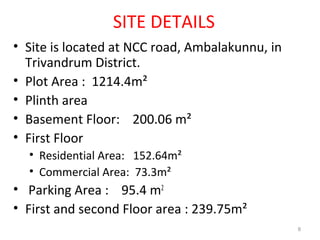
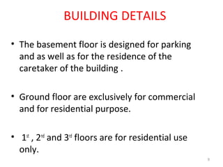
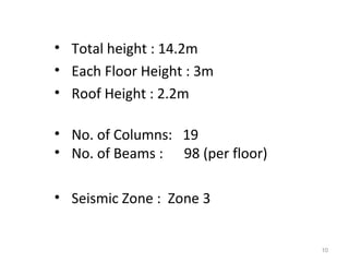
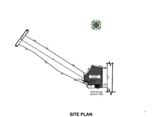
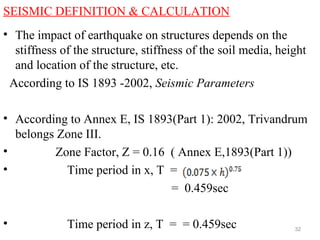
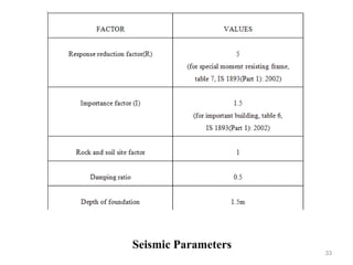
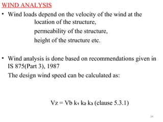
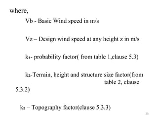
This document provides details of the structural analysis and design of a commercial and residential building using STAAD.Pro, AutoCAD, and STAAD.Foundation software. The building is located in Trivandrum, Kerala and consists of a basement, ground plus three floors. The document describes the site details, building plans, load calculations, modeling in STAAD.Pro, design of structural elements like beams, columns, foundation, and reinforcement details. Pile foundation is adopted based on the bore log details. The analysis helps gain knowledge of designing various components using structural analysis and design software.


![REFERENCE
• [1] “Design aids for reinforced concrete” SP 16-1980,
Bureau of Indian Standard, New Delhi.
• [2] “Structural Safety of Building – Loading Standard
Code of Practice”, IS 875-1964
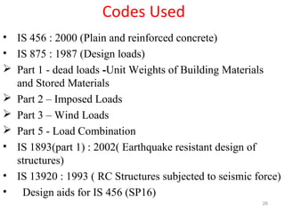
• [3] IS 456:2000(Plain and Reinforced Concrete Code)
• [4] IS 875-Part-1(1987)-“Code of practice for design
loads(Dead load)”
• [5] IS 875-Part-2(1987)-“Code of practice for dead
load(Live load)” 69](https://image.slidesharecdn.com/11editednew-160514094546/85/Analysis-and-design-of-building-69-320.jpg)
![• [6] IS 875-Part-3-“Wind loads on buildings and
Structures”
• [7] IS 875-Part-5- “Code of Practice for design
loads(Special loads and Combination)”
• [8] IS 1893-1(2002)-“Criteria foe earthquakeresistant
design of structures”
• [9] B.C Punmia, Ashok K. Jain; “Reinforced Concrete
Structures Volume I & II’, Standard publishers
Distributors, Delhi – 6”
• [10] Dr. N. Krishna Raju; “Design of RC Structures”,
CBS Publishers and Distributors, New Delhi, 2006
• [11] S. Ramamrutham and R. Narayan; “Design of
Reinforced Concrete Structures.” (conforming to IS
456). 70](https://image.slidesharecdn.com/11editednew-160514094546/85/Analysis-and-design-of-building-70-320.jpg)