Download to read offline
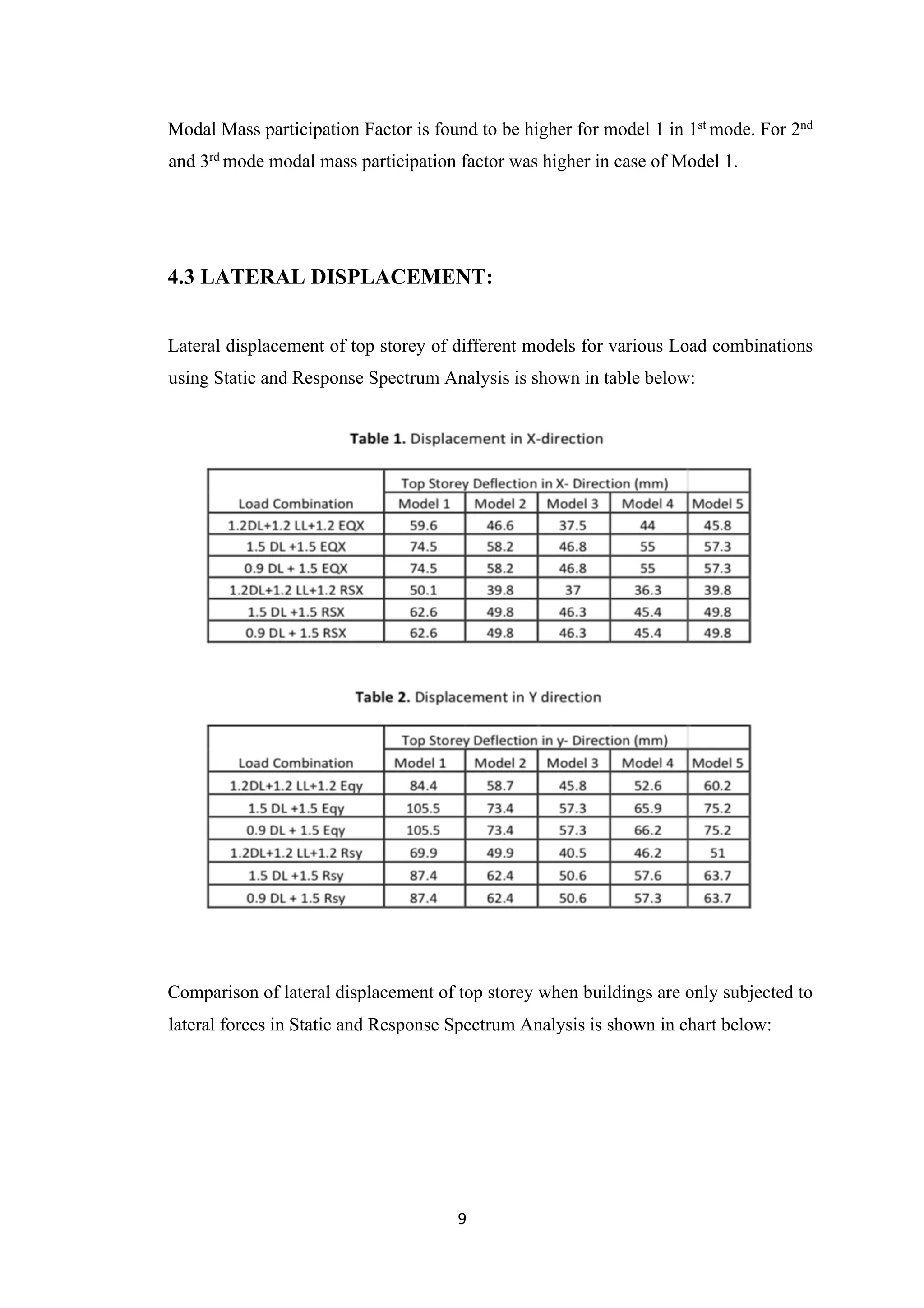

1. The document discusses modeling and analyzing a 10-story building with different shear wall configurations to determine the optimal layout. 5 models were considered: without shear walls, with center/side shear walls, and with corner shear walls extending different lengths. 2. Model 3, with corner shear walls extending 3m on each side, performed best with the lowest drift, highest stiffness, and least displacement under seismic and wind loads. Proper shear wall positioning improves a building's earthquake resistance. 3. Static analysis yielded higher drifts than response spectrum analysis for all models. Shear walls significantly influence member forces and building performance during seismic events. Model 3 displayed the best structural behavior overall.


![presentation]](https://cdn.slidesharecdn.com/ss_thumbnails/e66f3ab5-a49b-471e-8fdf-d93abb012839-160825182707-thumbnail.jpg?width=640&height=640&fit=bounds)


