Downloaded 2,520 times


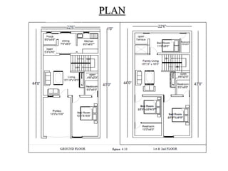
![LOAD TRANSFERRED TO BEAM FROM SLAB
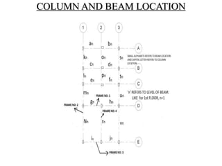
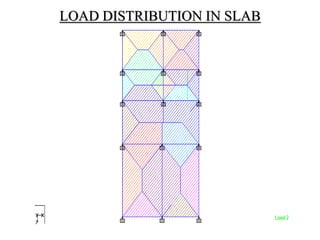
The load transferred to beam from slab is determined
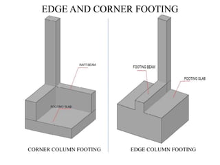
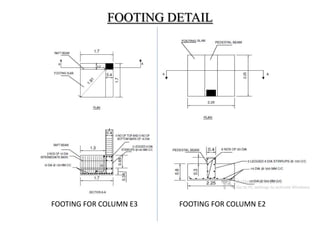
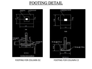
by using triangular, trapezoidal & rectangular
formula.
Trapezoidal formula =W * Lx / 6 [ 3-( Lx/ Ly )2 ]
Triangular formula = W * Lx / 3
Rectangular formula = W * Lx / 2](https://image.slidesharecdn.com/designproject-150221222013-conversion-gate02/85/Design-project-14-320.jpg)


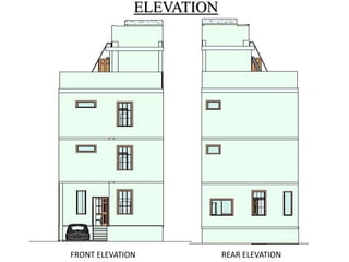
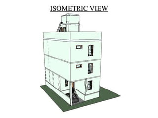
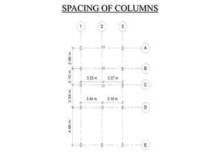
1) This document describes the design of a residential building located in Sirumalai, Dindigul district. It is a G+2 storied building located in a congested area without setbacks. 2) The methodology section outlines the process of drawing plans, locating columns and beams, applying dimensions, calculating loads, analyzing shear and bending moments, identifying critical structural elements, and designing the slab, beams, columns, and footings. 3) Key aspects of the design include the load calculations, analysis of the critical frame, design of the slab, beams, columns, and edge and corner footings. Reinforcement is designed according to code provisions.


