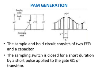
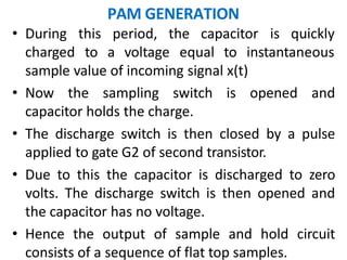
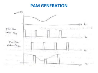
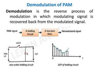
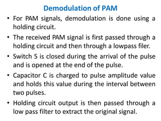
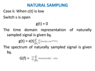
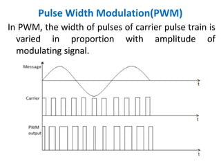
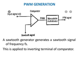
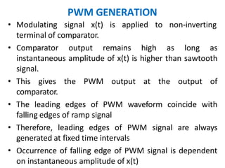
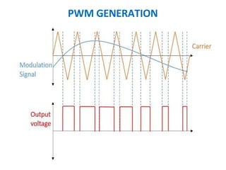
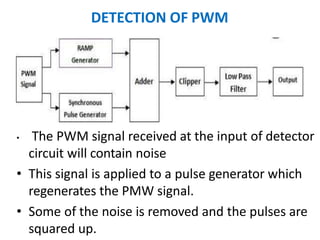
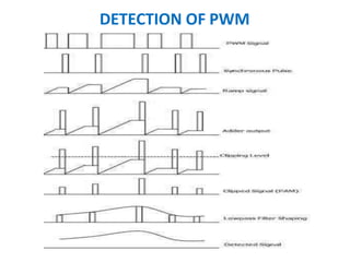
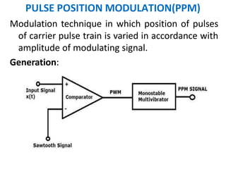
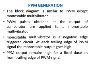
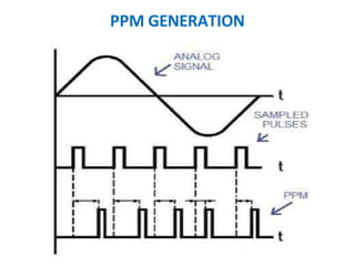
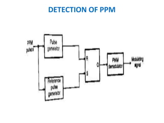
ANALOG COMMUNICATION SYSTEMS
By
Ms. Swati Shrrpal Halunde
Assistant Professor DEPT. of
E.C.E S.I.T.C.O.E. Yadrav-
Ichalkaranji
ANALOG PULSE MODULATION SCHEMES
Pulse Modulation:
The process of transmitting the signals in the form of
pulses by using some special techniques.
There are two types of pulse modulation systems,
1. Pulse Amplitude Modulation
2. Pulse Time Modulation
Pulse time modulation is further divided into,
• Pulse Width Modulation
• Pulse Position Modulation
PULSE AMPLITUDE MODULATION(PAM)
In Pulse amplitude modulation, the amplitude of
pulses of carrier pulse train is varied in
accordance with the modulating signal.
In PAM , the pulses can be flat top type or natural
type or ideal type.
Out of these, flat top PAM is widely used because of
easy noise removal.
PAM GENERATION
• The sample and hold circuit consists of two FETs
and a capacitor.
• The sampling switch is closed for a short duration
by a short pulse applied to the gate G1 of
transistor.
PAM GENERATION
period, the capacitor is quickly
• During this
charged to a voltage equal to instantaneous
sample value of incoming signal x(t)
• Now the sampling switch is opened and
capacitor holds the charge.
• The discharge switch is then closed by a pulse
applied to gate G2 of second transistor.
• Due to this the capacitor is discharged to zero
volts. The discharge switch is then opened and
the capacitor has no voltage.
• Hence the output of sample and hold circuit
consists of a sequence of flat top samples.
PAM GENERATION
Transmission bandwidth of PAM
In PAM signal the pulse duration τ is assumed to be
very small compared to time period Ts i.e τ< Ts
If the maximum frequency in the modulating signal
x(t) is fm then sampling frequency fs is given by
fs<=2fm Or 1/Ts <= 2fm or Ts <= 1/2fm
Therefore, τ< Ts <= 1/2fm
If ON and OFF time of PAM pulse is equal then
maximum frequency of PAM pulse will be fmax =
1/ τ+ τ = 1/2 τ
Therefore, transmission bandwidth >=1/2 τ >=
1/[2(1/2fm)>= fm
Demodulation of PAM
Demodulation
modulation
is the reverse process of
in which modulating signal is
recovered back from the modulated signal.
Demodulation of PAM
• For PAM signals, demodulation is done using a
holding circuit.
• The received PAM signal is first passed through a
holding circuit and then through a lowpass filer.
• Switch S is closed during the arrival of the pulse
and is opened at the end of the pulse.
• Capacitor C is charged to pulse amplitude value
and holds this value during the interval between
two pulses.
• Holding circuit output is then passed through a
low pass filter to extract the original signal.
Advantages, Disadvantages of PAM
Advantages:
• It is the simple process for modulation and
demodulation
• Transmitter and receiver circuits are simple and easy to
construct.
Disadvantages:
• Bandwidth requirement is high
• Interference of noise is maximum
• Power requirement is high
Applications:
• Used in microcontrollers for generating control signals
• Used as electronic driver for LED lighting
SAMPLING
It is the process of converting a continuous time
signal into a discrete time signal
During sampling, sufficient number of samples of
the signal must be taken so that original signal is
correctly represented in its samples and possible
for reconstruction.
Number of samples to be taken depends on
maximum signal frequency present in the signal.
• Different types of samples are,
• Ideal
• Natural
• Flat top
SAMPLING
Sampling theorem:
A continuous time signal may be completely
represented in its samples and recovered back if
the sampling frequency fs>2fm
Nyqyist rate and Nyquist interval:
When sampling rate becomes exactly equal to 2fm
samples per second, it is called Nyquist rate
fs=2fm Hz
Maximum sampling interval
interval.
Ts = 1/fs=1/2fm sec
is called Nyquist
NATURAL SAMPLING
In natural sampling, pulse has a finite width equal
to τ.
NATURAL SAMPLING
Let an analog continuous time signal x(t) sampled
at a rate fs Hz and sampling function c(t) which is
a train of periodic pulse of width τ and frequency
fs Hz
Case i: When c(t) is high
Switch S is closed and output g(t) is exactly equal to
input
g(t) = x(t)
NATURAL SAMPLING
Case ii: When c(t) is low
Switch s is open
g(t) = 0
The time domain representation of naturally
sampled signal is given by,
g(t) = x(t)
The spectrum of naturally sampled signal is given
by,
G(f) =
Pulse Width Modulation(PWM)
In PWM, the width of pulses of carrier pulse train is
varied in proportion with amplitude of
modulating signal.
PWM GENERATION
A sawtooth generator generates a sawtooth signal
of frequency fs.
This is applied to inverting terminal of comparator.
PWM GENERATION
• Modulating signal x(t) is applied to non-inverting
terminal of comparator.
• Comparator output remains high as long as
instantaneous amplitude of x(t) is higher than sawtooth
signal.
• This gives the PWM output at the output of
comparator.
• The leading edges of PWM waveform coincide with
falling edges of ramp signal
• Therefore, leading edges of PWM signal are always
generated at fixed time intervals
• Occurrence of falling edge of PWM signal is dependent
on instantaneous amplitude of x(t)
PWM GENERATION
DETECTION OF PWM
• The PWM signal received at the input of detector
circuit will contain noise
• This signal is applied to a pulse generator which
regenerates the PMW signal.
• Some of the noise is removed and the pulses are
squared up.
DETECTION OF PWM
• The regenerated pulses are applied to a reference pulse generator.
• It produces a train of constant amplitude and constant width
pulses.
• These pulses are synchronized to the leading edges of regenerated
PWM pulses but delayed by fixed intervals.
• The regenerated PWM pulses are also applied to a ramp generator
whose o/p is a constant slope ramp for the duration of the pulse.
• At the end of the pulse a sample and hold circuit retains the final
ramp voltage until it is reset at the end of the pulse.
• The constant amplitude pulses at the o/p of the reference
generator are then added to ramp signal.
• O/P of the adder is then clipped off at a threshold level to
generate a PAM signal.
• A low pass filter is used to recover the original modulating signal
back from PAM signal.
DETECTION OF PWM
PULSE POSITION MODULATION(PPM)
Modulation technique in which position of pulses
of carrier pulse train is varied in accordance with
amplitude of modulating signal.
Generation:
PPM GENERATION
• The block diagram is similar to PWM except
monostable multivibrator.
• PWM pulses obtained at the output of
to a monostable
comparator
multivibrator
.
• monostable
are applied
multivibrator is a negative edge
triggered circuit. At each trailing edge of PWM
signal the monostable output goes high.
• PPM output remains high for a fixed duration
from trailing edge of PWM signal.
PPM GENERATION
DETECTION OF PPM
DETECTION OF PPM
• The circuit consists of S-R flipflop which is set or
gives high output when reference pulses arrive.
• Reference pulses are generated by a reference
pulse generator.
• Flip-flop circuit is reset and gives low output at
the leading edge of PPM signal.
• The process repeats and we get PWM pulses at
the output of flip-flop.
• PWM pulses are then demodulated in a PWM
demodulator to get original modulating signal.
DETECTION OF PPM

Analog pulse modulation scheme.pptx

  • 1.
    ANALOG COMMUNICATION SYSTEMS By Ms.Swati Shrrpal Halunde Assistant Professor DEPT. of E.C.E S.I.T.C.O.E. Yadrav- Ichalkaranji ANALOG PULSE MODULATION SCHEMES
  • 2.
    ANALOG PULSE MODULATIONSCHEMES Pulse Modulation: The process of transmitting the signals in the form of pulses by using some special techniques. There are two types of pulse modulation systems, 1. Pulse Amplitude Modulation 2. Pulse Time Modulation Pulse time modulation is further divided into, • Pulse Width Modulation • Pulse Position Modulation
  • 3.
    PULSE AMPLITUDE MODULATION(PAM) InPulse amplitude modulation, the amplitude of pulses of carrier pulse train is varied in accordance with the modulating signal. In PAM , the pulses can be flat top type or natural type or ideal type. Out of these, flat top PAM is widely used because of easy noise removal.
  • 4.
    PAM GENERATION • Thesample and hold circuit consists of two FETs and a capacitor. • The sampling switch is closed for a short duration by a short pulse applied to the gate G1 of transistor.
  • 5.
    PAM GENERATION period, thecapacitor is quickly • During this charged to a voltage equal to instantaneous sample value of incoming signal x(t) • Now the sampling switch is opened and capacitor holds the charge. • The discharge switch is then closed by a pulse applied to gate G2 of second transistor. • Due to this the capacitor is discharged to zero volts. The discharge switch is then opened and the capacitor has no voltage. • Hence the output of sample and hold circuit consists of a sequence of flat top samples.
  • 6.
  • 7.
    Transmission bandwidth ofPAM In PAM signal the pulse duration τ is assumed to be very small compared to time period Ts i.e τ< Ts If the maximum frequency in the modulating signal x(t) is fm then sampling frequency fs is given by fs<=2fm Or 1/Ts <= 2fm or Ts <= 1/2fm Therefore, τ< Ts <= 1/2fm If ON and OFF time of PAM pulse is equal then maximum frequency of PAM pulse will be fmax = 1/ τ+ τ = 1/2 τ Therefore, transmission bandwidth >=1/2 τ >= 1/[2(1/2fm)>= fm
  • 8.
    Demodulation of PAM Demodulation modulation isthe reverse process of in which modulating signal is recovered back from the modulated signal.
  • 9.
    Demodulation of PAM •For PAM signals, demodulation is done using a holding circuit. • The received PAM signal is first passed through a holding circuit and then through a lowpass filer. • Switch S is closed during the arrival of the pulse and is opened at the end of the pulse. • Capacitor C is charged to pulse amplitude value and holds this value during the interval between two pulses. • Holding circuit output is then passed through a low pass filter to extract the original signal.
  • 10.
    Advantages, Disadvantages ofPAM Advantages: • It is the simple process for modulation and demodulation • Transmitter and receiver circuits are simple and easy to construct. Disadvantages: • Bandwidth requirement is high • Interference of noise is maximum • Power requirement is high Applications: • Used in microcontrollers for generating control signals • Used as electronic driver for LED lighting
  • 11.
    SAMPLING It is theprocess of converting a continuous time signal into a discrete time signal During sampling, sufficient number of samples of the signal must be taken so that original signal is correctly represented in its samples and possible for reconstruction. Number of samples to be taken depends on maximum signal frequency present in the signal. • Different types of samples are, • Ideal • Natural • Flat top
  • 12.
    SAMPLING Sampling theorem: A continuoustime signal may be completely represented in its samples and recovered back if the sampling frequency fs>2fm Nyqyist rate and Nyquist interval: When sampling rate becomes exactly equal to 2fm samples per second, it is called Nyquist rate fs=2fm Hz Maximum sampling interval interval. Ts = 1/fs=1/2fm sec is called Nyquist
  • 13.
    NATURAL SAMPLING In naturalsampling, pulse has a finite width equal to τ.
  • 14.
    NATURAL SAMPLING Let ananalog continuous time signal x(t) sampled at a rate fs Hz and sampling function c(t) which is a train of periodic pulse of width τ and frequency fs Hz Case i: When c(t) is high Switch S is closed and output g(t) is exactly equal to input g(t) = x(t)
  • 15.
    NATURAL SAMPLING Case ii:When c(t) is low Switch s is open g(t) = 0 The time domain representation of naturally sampled signal is given by, g(t) = x(t) The spectrum of naturally sampled signal is given by, G(f) =
  • 16.
    Pulse Width Modulation(PWM) InPWM, the width of pulses of carrier pulse train is varied in proportion with amplitude of modulating signal.
  • 17.
    PWM GENERATION A sawtoothgenerator generates a sawtooth signal of frequency fs. This is applied to inverting terminal of comparator.
  • 18.
    PWM GENERATION • Modulatingsignal x(t) is applied to non-inverting terminal of comparator. • Comparator output remains high as long as instantaneous amplitude of x(t) is higher than sawtooth signal. • This gives the PWM output at the output of comparator. • The leading edges of PWM waveform coincide with falling edges of ramp signal • Therefore, leading edges of PWM signal are always generated at fixed time intervals • Occurrence of falling edge of PWM signal is dependent on instantaneous amplitude of x(t)
  • 19.
  • 20.
    DETECTION OF PWM •The PWM signal received at the input of detector circuit will contain noise • This signal is applied to a pulse generator which regenerates the PMW signal. • Some of the noise is removed and the pulses are squared up.
  • 21.
    DETECTION OF PWM •The regenerated pulses are applied to a reference pulse generator. • It produces a train of constant amplitude and constant width pulses. • These pulses are synchronized to the leading edges of regenerated PWM pulses but delayed by fixed intervals. • The regenerated PWM pulses are also applied to a ramp generator whose o/p is a constant slope ramp for the duration of the pulse. • At the end of the pulse a sample and hold circuit retains the final ramp voltage until it is reset at the end of the pulse. • The constant amplitude pulses at the o/p of the reference generator are then added to ramp signal. • O/P of the adder is then clipped off at a threshold level to generate a PAM signal. • A low pass filter is used to recover the original modulating signal back from PAM signal.
  • 22.
  • 23.
    PULSE POSITION MODULATION(PPM) Modulationtechnique in which position of pulses of carrier pulse train is varied in accordance with amplitude of modulating signal. Generation:
  • 24.
    PPM GENERATION • Theblock diagram is similar to PWM except monostable multivibrator. • PWM pulses obtained at the output of to a monostable comparator multivibrator . • monostable are applied multivibrator is a negative edge triggered circuit. At each trailing edge of PWM signal the monostable output goes high. • PPM output remains high for a fixed duration from trailing edge of PWM signal.
  • 25.
  • 26.
  • 27.
    DETECTION OF PPM •The circuit consists of S-R flipflop which is set or gives high output when reference pulses arrive. • Reference pulses are generated by a reference pulse generator. • Flip-flop circuit is reset and gives low output at the leading edge of PPM signal. • The process repeats and we get PWM pulses at the output of flip-flop. • PWM pulses are then demodulated in a PWM demodulator to get original modulating signal.
  • 28.