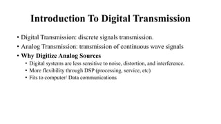
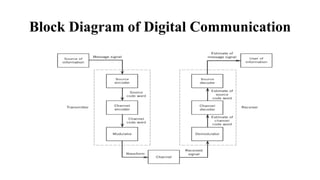
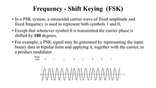
University of Gondar
Institute of Technology
Electrical Engineering Department
By:- Habte Aregawi
Introduction to Communication
(EEng4116 )
Pulse and Digital Modulation Techniques
Contents
• Introduction of Digital Communication
• Sampling Techniques for Analog Modulation Systems
• Pulse Amplitude Modulation (PAM)
• Pulse Position Modulation (PPM)
• Pulse Duration Modulation (PDM)
• Quantization
• Pulse code Modulation (PCM)
Introduction To Digital Transmission
• Digital Transmission: discrete signals transmission.
• Analog Transmission: transmission of continuous wave signals
• Why Digitize Analog Sources
• Digital systems are less sensitive to noise, distortion, and interference.
• More flexibility through DSP (processing, service, etc)
• Fits to computer/ Data communications
Block Diagram of Digital Communication
Sampling Theorem
• Sampling: - is a process that analog signal is converted into a
corresponding sequence of samples in the time domain.
• The samples are usually spaced uniformly in time.
• The operation is basic to digital signal processing and digital
communications.
• For a procedure to have practical utility, it is necessary that we choose
the sampling rate properly,
• The sequence of samples uniquely defines the original analog signal.
Instantaneous Sampling (1 of 3)
• Suppose that we sample the signal g(t)
instantaneously and at a uniform rate,
once every 𝑇𝑠 seconds.
• We obtain an infinite sequence of
samples spaced denoted by g 𝒏𝑻𝒔 ,
• Where n is all possible integer values.
• 𝑇𝑠 sampling period, sampling rate
𝒇𝒔 =
𝟏
𝑻𝒔
• The ideal sampled signal g𝛿 𝑡
g𝜹 𝒕 = ෍
𝒏=−∞
∞
g 𝒏𝑻𝒔 𝜹 𝒕 − 𝒏𝑻𝒔
Instantaneous Sampling (2 of 3)
• From the definition of the delta, we recall that such an idealized function
has unit area.
• For G(f) is the Fourier transform of the original signal g(t), The Fourier
transform of pair of sampled signal is:
g𝜹 𝒕 ⇌ 𝒇𝒔 ෍
𝒎=−∞
∞
𝑮(𝒇 − 𝒎𝒇𝒔)
• Sampling theorem for strictly band-limited signals of finite energy:
I. It is completely described by instantaneous sample values uniformly spaced in time
with period 𝑇𝑠 < Τ
1 2𝑊
II. The signal can exactly recovered from a knowledge of its samples taken at the rate
of 𝑓𝑠 ≥ 2𝑊 samples per second.
• The sampling rate of 2𝑊 samples per second, for a signal bandwidth
of 𝑊 Hertz, is called the Nyquist rate
• Its reciprocal Τ
1 2𝑊(measured in seconds) is called the Nyquist
interval.
Instantaneous Sampling (3 of 3)
Pulse Amplitude Modulation (PAM) (1 of 5)
• It is the simplest and most basic form of analog pulse modulation.
• The amplitudes of regularly spaced pulses are varied in proportion to
the corresponding sample values of a continuous message signal
• The pulses can be of a rectangular form or some other appropriate
shape
• The dashed curve depicts the waveform of a
message signal m(t ),
• The sequence of amplitude modulated
rectangular pulses shown as solid lines
represents the corresponding PAM signal s(t).
• There are two operations involved in the generation of the PAM signal
1. Instantaneous sampling of the message signal m(t) every 𝑇𝑠 seconds where
the sampling rate 𝑓𝑠 = Τ
1 𝑇𝑠, is chosen in accordance to sampling theorem
2. Lengthening the duration of each sample to obtained some constant value T
• In digital circuit technology, these two operations are jointly referred
to as “sample and hold.”
• One important reason for intentionally lengthening the duration of
each sample is to avoid the use of an excessive channel bandwidth
Pulse Amplitude Modulation (PAM) (2 of 5)
• The PAM signal can be expressed as:
𝒔 𝒕 = ෍
𝒏=−∞
∞
m 𝒏𝑻𝒔 𝒉 𝒕 − 𝒏𝑻𝒔
• The ℎ 𝑡 is a standard rectangular pulse of unit amplitude and
duration 𝑇, defined as
ℎ 𝑡 =
1 0 < 𝑡 < 𝑇
1
2
𝑡 = 0, 𝑡 = 𝑇
0, 𝑜𝑡ℎ𝑒𝑟𝑤𝑖𝑠𝑒𝑠
Pulse Amplitude Modulation (PAM) (3 of 5)
• The instantaneously sampled version of m(t) is given by
m𝜹 𝒕 = ෍
𝒏=−∞
∞
m 𝒏𝑻𝒔 𝜹 𝒕 − 𝒏𝑻𝒔
• Convolving m𝛿 𝑡 with the pulse ℎ 𝑡
𝒔 𝒕 = m𝜹 𝒕 ⋆ 𝒉 𝒕 = ෍
𝒏=−∞
∞
m 𝒏𝑻𝒔 𝒉 𝒕 − 𝒏𝑻𝒔
• Taking the Fourier transform of both sides
𝑆 𝑓 = M𝛿 𝑓 𝐻 𝑓 = 𝒇𝒔 ෍
𝒌=−∞
∞
𝑴 𝒇 − 𝒌𝒇𝒔 𝑯(𝒇)
Pulse Amplitude Modulation (PAM) (4 of 5)
* =
Pulse Amplitude Modulation (PAM) (5 of 5)
Reconstruction PAM Signals (1 of 3)
• First step, passing 𝒔 𝒕 through a low-pass
filter whose frequency response is defined.
• The spectrum of the resulting filter output is
equal to M 𝑓 𝐻 𝑓
• This output is equivalent to passing the
original message signal m 𝑡 through
another low-pass filter of transfer function
𝐻 𝑓 .
Amplitude response of reconstruction filter
Reconstructing PAM Signals
• Since using flat-top samples to generate a PAM signal, we have
introduced amplitude distortion as well as a delay of
𝑇
2
.
• The distortion caused by the use of referred to as the aperture effect.
• This distortion may be corrected by connecting an equalizer in cascade
with the low-pass reconstruction filter.
• The equalizer has the effect of decreasing the in-band loss of the
reconstruction filter as the frequency increases in such a manner as to
compensate for the aperture effect.
Reconstruction PAM Signals (2 of 3)
Ideally, amplitude
response of the
equalizer
• The noise performance of a PAM system
can never be better than baseband-signal
transmission.
• For transmission over long distances, PAM
would be used only as a means of message
processing for time-division multiplexing
• From which conversion to some other
form of pulse modulation is subsequently
made
Figure: Flat-top sampling
Reconstruction PAM Signals (3 of 3)
Time-division Multiplexing (TDM)
Pulse-Width Modulation (PWM) (1 of 2)
• Analog pulse modulation results when some attribute of a pulse varies continuously
in one-to-one correspondence with a sample value.
• A PWM waveform consists of a sequence pulse having a width proportional to the
values of the message signal at the sampling instants.
• If the message is 0 at the sampling time, the width of the PWM pulse is typically
(1/2)𝑇𝑠.
• Thus, pulse widths less than (1/2)𝑇𝑠 correspond to negative sample values, and pulse
widths greater than (1/2)𝑇𝑠 correspond to positive sample values.
• The maximum pulse width of the PWM pulses is exactly equal to the sampling
period 1∕𝑇𝑠.
• This form of modulation is also referred to Pulse-Duration Modulation(PDM) or
or pulse-length modulation
• PWM is seldom used in modern communications systems.
• However, PWM has found extensively for DC motor control in which
motor speed is proportional to the width of the pulses.
• Large amplitude pulses are therefore avoided.
• Since the pulses have equal amplitude, the energy in a given pulse is
proportional to the pulse width.
• The sample values can be recovered from a PWM waveform by
lowpass filtering
Pulse-Width Modulation (PWM) (2 of 2)
Illustration of Pulse Modulations
Pulse-Position Modulation (PPM) (1 of 3)
• A PPM signal consists of a sequence of pulses in which the pulse
displacement from a specified time reference is proportional to the
sample values of the information-bearing signal.
• In PDM, long pulses expend considerable power during the pulse
while bearing no additional information.
• If this unused power is subtracted from PDM, so that only time
transitions are preserved
• WE obtain a more efficient type of pulse modulation known as pulse-
position modulation (PPM).
• In PPM, the position of a pulse relative to its unmodulated time of occurrence is varied in
accordance with the message signal.
• Using the sample 𝑚(𝑛𝑇𝑠) of a message signal m(t) to modulate the position of the nth
pulse, we obtain the PPM signal
𝑠 𝑡 = ෍
−∞
∞
g(𝑡 − 𝑛𝑇𝑠 − 𝑘𝑝𝑚(𝑛𝑇𝑠))
• Where 𝑘𝑝is modulation sensitivity of the pulse-position modulator and g(t) denotes a
standard pulse of interest.
• Clearly, the different pulses constituting the PPM signal s(t) must be strictly
nonoverlapping;
• Sufficient condition for this requirement to be satisfied is to have
g 𝑡 = 0, 𝑡 >
𝑇𝑠
2
− 𝑘𝑝 𝑚 𝑡 𝑚𝑎𝑥 ⇒
𝑇𝑠
2
> 𝑘𝑝 𝑚(𝑡) 𝑚𝑎𝑥
Pulse-Position Modulation (PPM) (2 of 3)
• The closer 𝑘𝑝 𝑚(𝑡) 𝑚𝑎𝑥 is to one half the sampling duration Ts,
• The narrower must the standard pulse g(t) be in order to ensure that the
individual pulses of the PPM signal s(t) do not interfere with each other, and
• The wider will the bandwidth occupied by the PPM signal.
• The signal samples 𝑚(𝑛𝑇𝑠) can be recovered perfectly.
Pulse-Position Modulation (PPM) (3 of 3)
Pulse
generator
Sample and
hold circuit
Adder
Threshold
detector
Pulse
shaping
filter
Sawtooth
generator
Message
signal m(t)
u(t) v(t) i(t) PPM signal
s(t)
Figure: Block diagram of PPM generator.
Advantage of PPM
• In the context of noise performance, a PPM system represents the
optimum form of analog pulse modulation.
• PPM and FM systems exhibit a similar noise performance.
Reading Assignment
DETECTION OF PPM WAVES
Digital Pulse Modulation
• Digital modulation alleviate a trade-off of increased transmission
bandwidth and improved noise performance.
• There are two fundamental processes
• Sampling
• Quantizing
• Amplitude quantization is defined as the process of transforming the
sample amplitude m(nTs) of a message signal m(t) at time t = nTs
into a discrete amplitude v(nTs) taken from a finite set of possible
amplitudes.
• The quantization process is memoryless and instantaneous,
• The transformation at time t = nTs is not affected by earlier or later
samples of the message signal.
• The spacing between two adjacent representation levels is called a
quantum or step-size.
Digital Pulse Modulation
• The use of quantization introduces an error defined as the difference
between the input signal m and the output signal v.
• This error is called quantization noise.
Digital Pulse Modulation
Pulse-Code Modulation (PCM) (1 of 5)
• It is the most basic form of digital pulse modulation.
• In PCM a message signal is represented by a sequence of coded
pulses,
• Which is accomplished by representing the signal in discrete form in
both time and amplitude.
Lowpass
filter
Sampler Quantizer Encoder
Continuous time
message signal
PCM signal
Figure: Transmitter block diagram of PCM
• The low-pass filter prior to sampling is included to prevent aliasing of the
message signal.
• The quantizing and encoding operations are usually performed in the same
circuit, which is called an analog-to-digital converter.
• Sampling: The incoming message signal is sampled with a train of narrow
rectangular pulses so as to closely approximate the instantaneous sampling
process.
• Quantization: The sampled version of the message signal is then
quantized, thereby providing a new representation of the signal that is
discrete in both time and amplitude.
Pulse-Code Modulation (PCM) (2 of 5)
• ENCODING: process to translate the discrete set of sample values to
a more appropriate form of signal.
• Any plan for representing each of this discrete set of values as a
particular arrangement of discrete events is called a code
• One of the discrete events in a code is called a code element or
symbol.
• For example, the presence or absence of a pulse is a symbol.
• A particular arrangement of symbols used in a code to represent a
single value of the discrete set is called a codeword or character.
Pulse-Code Modulation (PCM) (3 of 5)
• In a binary code, each symbol may be either of two distinct values or
kinds, such as the presence or absence of a pulse.
• The two symbols of a binary code are customarily denoted as 0 and 1.
• The maximum advantage over the effects of noise in a transmission
medium is obtained by using a binary code,
• Because a binary symbol withstands a relatively high level of noise
and is easy to regenerate.
• Suppose that, in a binary code, each code word consists of R bits
(binary digit)
• R denotes the number of bits per sample.
Pulse-Code Modulation (PCM) (4 of 5)
• Then, using such a code, we may represent a total of 2𝑅 distinct
numbers.
• For example, a sample quantized into one of 256 levels may be
represented by an 8-bit code word
• LINE CODES: a binary stream of data takes on an electrical
representation.
• Anyone of several line codes can be used for the electrical
representation of a binary data stream.
Pulse-Code Modulation (PCM) (5 of 5)
The PCM Process
Line codes
• It is in a line code that a binary stream of data takes on an electrical
representation.
• There are five commonly used line code signaling
1. Unipolar Nonreturn-to-Zero (NRZ)
2. Polar Nonreturn-to-Zero (NRZ)
3. Unipolar Return-to-Zero (RZ)
4. Bipolar Return-to-Zero (BRZ)
5. Split-Phase (Manchester Code)
• Return-to-zero implies that the pulse shape used to represent the bit
always returns to the 0 volts or the neutral level before the end of the bit.
• Nonreturn-to-zero indicates that the pulse does not necessarily return to
the neutral level before the end of the bit.
Unipolar or On-Off Keying (OOK)
1. Unipolar or On-Off Keying (OOK): The presence of pulse
represents a 1 and the absence of pulse represents a 0.
• There are two variations in Unipolar signaling
• Non Return to Zero (NRZ)
• Return to Zero (RZ)
Polar Signaling
2. Polar Signaling
• There are two methods of Polar Signaling
• Polar NRZ
• Polar RZ
Bi-polar Signaling
3. Bi-polar: is an encoding technique which has three voltage levels
namely +, - and 0. Such a signal is called as duo-binary signal.
• For a 1, the voltage level gets a transition from + to – or from – to +, having
alternate 1s to be of equal polarity. A 0 will have a zero voltage level.
Polar Nonreturn-to-Zero (NRZ)
Unipolar Nonreturn-to-Zero (NRZ)
Unipolar Return-to-Zero (RZ)
Bipolar Return-to-Zero (RZ)
Split-Phase (Manchester Code)
Differential PCM
• Samples of the bandlimited signal are correlated
• Previous samples give information about the next one.
• Example, If the previous samples are small, the next one will be small
with high probability.
• This can be used to improve PCM performance: to decrease the
number of bits used (and hence, the bandwidth)
• Main idea: quantize and transmit the difference between two adjacent
samples, rather than the samples.
• Since the adjacent samples are correlated, their difference is small and
requires less bits to transmit.
Delta Modulation (DM)
• In delta modulation (DM), an incoming message signal is oversampled
(i.e., at a rate much higher than the Nyquist rate).
• The oversampled purposely increase the correlation between adjacent
samples of the signal.
• In DM the sampling rate is much higher and in which the step-size Δ
after quantization is of a smaller value.
• Delta Modulation is a simplified form of DPCM technique
• When it is required to transmit binary data over band-pass
communication channels such as radio links or satellite channels,
• It is necessary to modulate the signal onto a carrier wave (usually
sinusoidal) with fixed frequency limits set by the particular channel.
• The modulation process corresponds to switching or keying the
amplitude, frequency, or phase of the carrier between either of two
possible values corresponding to binary symbols 0 and 1.
• This results in three basic signaling techniques, namely,
• Amplitude - Shift Keying ( ASK),
• Frequency - Shift Keying (FSK), and
• Phase - Shift Keying (PSK)
Introduction to digital modulation techniques
Amplitude - Shift Keying (ASK)
• For ASK, binary symbol 1 is represented by transmitting a sinusoidal carrier
wave of fixed amplitude and fixed frequency for the bit duration Tb seconds,
• whereas binary symbol 0 is represented by switching off the carrier for Tb
seconds.
• For example, an ASK signal may be generated by using the on-off form of
representation for the input binary data
• Then applying it together with the carrier to a product modulator.
Frequency - Shift Keying (FSK)
• In an FSK system, two sinusoidal waves of the same amplitude but
different frequencies are used to represent binary symbols 1 and 0.
• An FSK signal may be generated by using the bipolar form of
representation for the input binary data and
• Then applying it to a voltage controlled oscillator, or by switching
between two oscillators.
Frequency - Shift Keying (FSK)
• In a PSK system, a sinusoidal carrier wave of fixed amplitude and
fixed frequency is used to represent both symbols 1 and 0,
• Except that whenever symbol 0 is transmitted the carrier phase is
shifted by 180 degrees.
• For example, a PSK signal may be generated by representing the input
binary data in bipolar form and applying it, together with the carrier, to
a product modulator.
End

Chapter Four.pdf ffhgfch fygbyd fehfhugd

  • 1.
    University of Gondar Instituteof Technology Electrical Engineering Department By:- Habte Aregawi Introduction to Communication (EEng4116 ) Pulse and Digital Modulation Techniques
  • 2.
    Contents • Introduction ofDigital Communication • Sampling Techniques for Analog Modulation Systems • Pulse Amplitude Modulation (PAM) • Pulse Position Modulation (PPM) • Pulse Duration Modulation (PDM) • Quantization • Pulse code Modulation (PCM)
  • 3.
    Introduction To DigitalTransmission • Digital Transmission: discrete signals transmission. • Analog Transmission: transmission of continuous wave signals • Why Digitize Analog Sources • Digital systems are less sensitive to noise, distortion, and interference. • More flexibility through DSP (processing, service, etc) • Fits to computer/ Data communications
  • 4.
    Block Diagram ofDigital Communication
  • 5.
    Sampling Theorem • Sampling:- is a process that analog signal is converted into a corresponding sequence of samples in the time domain. • The samples are usually spaced uniformly in time. • The operation is basic to digital signal processing and digital communications. • For a procedure to have practical utility, it is necessary that we choose the sampling rate properly, • The sequence of samples uniquely defines the original analog signal.
  • 6.
    Instantaneous Sampling (1of 3) • Suppose that we sample the signal g(t) instantaneously and at a uniform rate, once every 𝑇𝑠 seconds. • We obtain an infinite sequence of samples spaced denoted by g 𝒏𝑻𝒔 , • Where n is all possible integer values. • 𝑇𝑠 sampling period, sampling rate 𝒇𝒔 = 𝟏 𝑻𝒔 • The ideal sampled signal g𝛿 𝑡 g𝜹 𝒕 = ෍ 𝒏=−∞ ∞ g 𝒏𝑻𝒔 𝜹 𝒕 − 𝒏𝑻𝒔
  • 7.
    Instantaneous Sampling (2of 3) • From the definition of the delta, we recall that such an idealized function has unit area. • For G(f) is the Fourier transform of the original signal g(t), The Fourier transform of pair of sampled signal is: g𝜹 𝒕 ⇌ 𝒇𝒔 ෍ 𝒎=−∞ ∞ 𝑮(𝒇 − 𝒎𝒇𝒔) • Sampling theorem for strictly band-limited signals of finite energy: I. It is completely described by instantaneous sample values uniformly spaced in time with period 𝑇𝑠 < Τ 1 2𝑊 II. The signal can exactly recovered from a knowledge of its samples taken at the rate of 𝑓𝑠 ≥ 2𝑊 samples per second.
  • 8.
    • The samplingrate of 2𝑊 samples per second, for a signal bandwidth of 𝑊 Hertz, is called the Nyquist rate • Its reciprocal Τ 1 2𝑊(measured in seconds) is called the Nyquist interval. Instantaneous Sampling (3 of 3)
  • 9.
    Pulse Amplitude Modulation(PAM) (1 of 5) • It is the simplest and most basic form of analog pulse modulation. • The amplitudes of regularly spaced pulses are varied in proportion to the corresponding sample values of a continuous message signal • The pulses can be of a rectangular form or some other appropriate shape • The dashed curve depicts the waveform of a message signal m(t ), • The sequence of amplitude modulated rectangular pulses shown as solid lines represents the corresponding PAM signal s(t).
  • 10.
    • There aretwo operations involved in the generation of the PAM signal 1. Instantaneous sampling of the message signal m(t) every 𝑇𝑠 seconds where the sampling rate 𝑓𝑠 = Τ 1 𝑇𝑠, is chosen in accordance to sampling theorem 2. Lengthening the duration of each sample to obtained some constant value T • In digital circuit technology, these two operations are jointly referred to as “sample and hold.” • One important reason for intentionally lengthening the duration of each sample is to avoid the use of an excessive channel bandwidth Pulse Amplitude Modulation (PAM) (2 of 5)
  • 11.
    • The PAMsignal can be expressed as: 𝒔 𝒕 = ෍ 𝒏=−∞ ∞ m 𝒏𝑻𝒔 𝒉 𝒕 − 𝒏𝑻𝒔 • The ℎ 𝑡 is a standard rectangular pulse of unit amplitude and duration 𝑇, defined as ℎ 𝑡 = 1 0 < 𝑡 < 𝑇 1 2 𝑡 = 0, 𝑡 = 𝑇 0, 𝑜𝑡ℎ𝑒𝑟𝑤𝑖𝑠𝑒𝑠 Pulse Amplitude Modulation (PAM) (3 of 5)
  • 12.
    • The instantaneouslysampled version of m(t) is given by m𝜹 𝒕 = ෍ 𝒏=−∞ ∞ m 𝒏𝑻𝒔 𝜹 𝒕 − 𝒏𝑻𝒔 • Convolving m𝛿 𝑡 with the pulse ℎ 𝑡 𝒔 𝒕 = m𝜹 𝒕 ⋆ 𝒉 𝒕 = ෍ 𝒏=−∞ ∞ m 𝒏𝑻𝒔 𝒉 𝒕 − 𝒏𝑻𝒔 • Taking the Fourier transform of both sides 𝑆 𝑓 = M𝛿 𝑓 𝐻 𝑓 = 𝒇𝒔 ෍ 𝒌=−∞ ∞ 𝑴 𝒇 − 𝒌𝒇𝒔 𝑯(𝒇) Pulse Amplitude Modulation (PAM) (4 of 5)
  • 13.
    * = Pulse AmplitudeModulation (PAM) (5 of 5)
  • 14.
    Reconstruction PAM Signals(1 of 3) • First step, passing 𝒔 𝒕 through a low-pass filter whose frequency response is defined. • The spectrum of the resulting filter output is equal to M 𝑓 𝐻 𝑓 • This output is equivalent to passing the original message signal m 𝑡 through another low-pass filter of transfer function 𝐻 𝑓 . Amplitude response of reconstruction filter Reconstructing PAM Signals
  • 15.
    • Since usingflat-top samples to generate a PAM signal, we have introduced amplitude distortion as well as a delay of 𝑇 2 . • The distortion caused by the use of referred to as the aperture effect. • This distortion may be corrected by connecting an equalizer in cascade with the low-pass reconstruction filter. • The equalizer has the effect of decreasing the in-band loss of the reconstruction filter as the frequency increases in such a manner as to compensate for the aperture effect. Reconstruction PAM Signals (2 of 3) Ideally, amplitude response of the equalizer
  • 16.
    • The noiseperformance of a PAM system can never be better than baseband-signal transmission. • For transmission over long distances, PAM would be used only as a means of message processing for time-division multiplexing • From which conversion to some other form of pulse modulation is subsequently made Figure: Flat-top sampling Reconstruction PAM Signals (3 of 3)
  • 17.
  • 18.
    Pulse-Width Modulation (PWM)(1 of 2) • Analog pulse modulation results when some attribute of a pulse varies continuously in one-to-one correspondence with a sample value. • A PWM waveform consists of a sequence pulse having a width proportional to the values of the message signal at the sampling instants. • If the message is 0 at the sampling time, the width of the PWM pulse is typically (1/2)𝑇𝑠. • Thus, pulse widths less than (1/2)𝑇𝑠 correspond to negative sample values, and pulse widths greater than (1/2)𝑇𝑠 correspond to positive sample values. • The maximum pulse width of the PWM pulses is exactly equal to the sampling period 1∕𝑇𝑠. • This form of modulation is also referred to Pulse-Duration Modulation(PDM) or or pulse-length modulation
  • 19.
    • PWM isseldom used in modern communications systems. • However, PWM has found extensively for DC motor control in which motor speed is proportional to the width of the pulses. • Large amplitude pulses are therefore avoided. • Since the pulses have equal amplitude, the energy in a given pulse is proportional to the pulse width. • The sample values can be recovered from a PWM waveform by lowpass filtering Pulse-Width Modulation (PWM) (2 of 2)
  • 20.
  • 21.
    Pulse-Position Modulation (PPM)(1 of 3) • A PPM signal consists of a sequence of pulses in which the pulse displacement from a specified time reference is proportional to the sample values of the information-bearing signal. • In PDM, long pulses expend considerable power during the pulse while bearing no additional information. • If this unused power is subtracted from PDM, so that only time transitions are preserved • WE obtain a more efficient type of pulse modulation known as pulse- position modulation (PPM).
  • 22.
    • In PPM,the position of a pulse relative to its unmodulated time of occurrence is varied in accordance with the message signal. • Using the sample 𝑚(𝑛𝑇𝑠) of a message signal m(t) to modulate the position of the nth pulse, we obtain the PPM signal 𝑠 𝑡 = ෍ −∞ ∞ g(𝑡 − 𝑛𝑇𝑠 − 𝑘𝑝𝑚(𝑛𝑇𝑠)) • Where 𝑘𝑝is modulation sensitivity of the pulse-position modulator and g(t) denotes a standard pulse of interest. • Clearly, the different pulses constituting the PPM signal s(t) must be strictly nonoverlapping; • Sufficient condition for this requirement to be satisfied is to have g 𝑡 = 0, 𝑡 > 𝑇𝑠 2 − 𝑘𝑝 𝑚 𝑡 𝑚𝑎𝑥 ⇒ 𝑇𝑠 2 > 𝑘𝑝 𝑚(𝑡) 𝑚𝑎𝑥 Pulse-Position Modulation (PPM) (2 of 3)
  • 23.
    • The closer𝑘𝑝 𝑚(𝑡) 𝑚𝑎𝑥 is to one half the sampling duration Ts, • The narrower must the standard pulse g(t) be in order to ensure that the individual pulses of the PPM signal s(t) do not interfere with each other, and • The wider will the bandwidth occupied by the PPM signal. • The signal samples 𝑚(𝑛𝑇𝑠) can be recovered perfectly. Pulse-Position Modulation (PPM) (3 of 3)
  • 24.
  • 25.
    Advantage of PPM •In the context of noise performance, a PPM system represents the optimum form of analog pulse modulation. • PPM and FM systems exhibit a similar noise performance.
  • 26.
  • 27.
    Digital Pulse Modulation •Digital modulation alleviate a trade-off of increased transmission bandwidth and improved noise performance. • There are two fundamental processes • Sampling • Quantizing • Amplitude quantization is defined as the process of transforming the sample amplitude m(nTs) of a message signal m(t) at time t = nTs into a discrete amplitude v(nTs) taken from a finite set of possible amplitudes.
  • 28.
    • The quantizationprocess is memoryless and instantaneous, • The transformation at time t = nTs is not affected by earlier or later samples of the message signal. • The spacing between two adjacent representation levels is called a quantum or step-size. Digital Pulse Modulation
  • 29.
    • The useof quantization introduces an error defined as the difference between the input signal m and the output signal v. • This error is called quantization noise. Digital Pulse Modulation
  • 30.
    Pulse-Code Modulation (PCM)(1 of 5) • It is the most basic form of digital pulse modulation. • In PCM a message signal is represented by a sequence of coded pulses, • Which is accomplished by representing the signal in discrete form in both time and amplitude. Lowpass filter Sampler Quantizer Encoder Continuous time message signal PCM signal Figure: Transmitter block diagram of PCM
  • 31.
    • The low-passfilter prior to sampling is included to prevent aliasing of the message signal. • The quantizing and encoding operations are usually performed in the same circuit, which is called an analog-to-digital converter. • Sampling: The incoming message signal is sampled with a train of narrow rectangular pulses so as to closely approximate the instantaneous sampling process. • Quantization: The sampled version of the message signal is then quantized, thereby providing a new representation of the signal that is discrete in both time and amplitude. Pulse-Code Modulation (PCM) (2 of 5)
  • 32.
    • ENCODING: processto translate the discrete set of sample values to a more appropriate form of signal. • Any plan for representing each of this discrete set of values as a particular arrangement of discrete events is called a code • One of the discrete events in a code is called a code element or symbol. • For example, the presence or absence of a pulse is a symbol. • A particular arrangement of symbols used in a code to represent a single value of the discrete set is called a codeword or character. Pulse-Code Modulation (PCM) (3 of 5)
  • 33.
    • In abinary code, each symbol may be either of two distinct values or kinds, such as the presence or absence of a pulse. • The two symbols of a binary code are customarily denoted as 0 and 1. • The maximum advantage over the effects of noise in a transmission medium is obtained by using a binary code, • Because a binary symbol withstands a relatively high level of noise and is easy to regenerate. • Suppose that, in a binary code, each code word consists of R bits (binary digit) • R denotes the number of bits per sample. Pulse-Code Modulation (PCM) (4 of 5)
  • 34.
    • Then, usingsuch a code, we may represent a total of 2𝑅 distinct numbers. • For example, a sample quantized into one of 256 levels may be represented by an 8-bit code word • LINE CODES: a binary stream of data takes on an electrical representation. • Anyone of several line codes can be used for the electrical representation of a binary data stream. Pulse-Code Modulation (PCM) (5 of 5)
  • 35.
  • 36.
    Line codes • Itis in a line code that a binary stream of data takes on an electrical representation. • There are five commonly used line code signaling 1. Unipolar Nonreturn-to-Zero (NRZ) 2. Polar Nonreturn-to-Zero (NRZ) 3. Unipolar Return-to-Zero (RZ) 4. Bipolar Return-to-Zero (BRZ) 5. Split-Phase (Manchester Code) • Return-to-zero implies that the pulse shape used to represent the bit always returns to the 0 volts or the neutral level before the end of the bit. • Nonreturn-to-zero indicates that the pulse does not necessarily return to the neutral level before the end of the bit.
  • 37.
    Unipolar or On-OffKeying (OOK) 1. Unipolar or On-Off Keying (OOK): The presence of pulse represents a 1 and the absence of pulse represents a 0. • There are two variations in Unipolar signaling • Non Return to Zero (NRZ) • Return to Zero (RZ)
  • 38.
    Polar Signaling 2. PolarSignaling • There are two methods of Polar Signaling • Polar NRZ • Polar RZ
  • 39.
    Bi-polar Signaling 3. Bi-polar:is an encoding technique which has three voltage levels namely +, - and 0. Such a signal is called as duo-binary signal. • For a 1, the voltage level gets a transition from + to – or from – to +, having alternate 1s to be of equal polarity. A 0 will have a zero voltage level.
  • 40.
    Polar Nonreturn-to-Zero (NRZ) UnipolarNonreturn-to-Zero (NRZ) Unipolar Return-to-Zero (RZ) Bipolar Return-to-Zero (RZ) Split-Phase (Manchester Code)
  • 41.
    Differential PCM • Samplesof the bandlimited signal are correlated • Previous samples give information about the next one. • Example, If the previous samples are small, the next one will be small with high probability. • This can be used to improve PCM performance: to decrease the number of bits used (and hence, the bandwidth) • Main idea: quantize and transmit the difference between two adjacent samples, rather than the samples. • Since the adjacent samples are correlated, their difference is small and requires less bits to transmit.
  • 42.
    Delta Modulation (DM) •In delta modulation (DM), an incoming message signal is oversampled (i.e., at a rate much higher than the Nyquist rate). • The oversampled purposely increase the correlation between adjacent samples of the signal. • In DM the sampling rate is much higher and in which the step-size Δ after quantization is of a smaller value. • Delta Modulation is a simplified form of DPCM technique
  • 43.
    • When itis required to transmit binary data over band-pass communication channels such as radio links or satellite channels, • It is necessary to modulate the signal onto a carrier wave (usually sinusoidal) with fixed frequency limits set by the particular channel. • The modulation process corresponds to switching or keying the amplitude, frequency, or phase of the carrier between either of two possible values corresponding to binary symbols 0 and 1. • This results in three basic signaling techniques, namely, • Amplitude - Shift Keying ( ASK), • Frequency - Shift Keying (FSK), and • Phase - Shift Keying (PSK) Introduction to digital modulation techniques
  • 44.
    Amplitude - ShiftKeying (ASK) • For ASK, binary symbol 1 is represented by transmitting a sinusoidal carrier wave of fixed amplitude and fixed frequency for the bit duration Tb seconds, • whereas binary symbol 0 is represented by switching off the carrier for Tb seconds. • For example, an ASK signal may be generated by using the on-off form of representation for the input binary data • Then applying it together with the carrier to a product modulator.
  • 45.
    Frequency - ShiftKeying (FSK) • In an FSK system, two sinusoidal waves of the same amplitude but different frequencies are used to represent binary symbols 1 and 0. • An FSK signal may be generated by using the bipolar form of representation for the input binary data and • Then applying it to a voltage controlled oscillator, or by switching between two oscillators.
  • 46.
    Frequency - ShiftKeying (FSK) • In a PSK system, a sinusoidal carrier wave of fixed amplitude and fixed frequency is used to represent both symbols 1 and 0, • Except that whenever symbol 0 is transmitted the carrier phase is shifted by 180 degrees. • For example, a PSK signal may be generated by representing the input binary data in bipolar form and applying it, together with the carrier, to a product modulator.
  • 47.