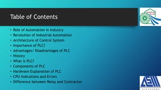
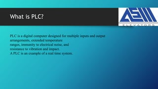
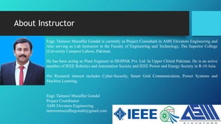
An Overview of PLC for
Electrical Engineers
Instructor:
Engr. Taimoor Muzaffar Gondal
Electrical Engineer
taimoormuzaffargondal@gmail.com
Table of Contents
• Role of Automation in Industry
• Revolution of Industrial Automation
• Architecture of Control System
• Importance of PLC?
• Advantages/ Disadvantages of PLC
• History
• What is PLC?
• Components of PLC
• Hardware Explanation of PLC
• CPU Indications and Errors
• Difference between Relay and Contractor
Table of Contents
What is RTU
Difference Between DCS and SCADA
HMI and PLC
Why we use 4-20 mA
Difference Between PLC, DCS and SCADA
PLC Memory
SCADA Basics
Role of Automation in Industry
Why We Need Automation
Industrial Automation- Revolution
Architecture of Control System
3- Information Level
2- Control Level (PLC/DCS)
1- Field Level
1- Field level is based on AC/DC, Motors, Valve, Relays, Sensors,
Bar Sensing and Measuring Related Things.
3- Information Level: HMI, SCADA etc
Importance of PLC?
Wherever automation is desired the PLCs are best suited to meet the task
Few examples of industries where PLCs are used:
1. Robots manufacturing and control
2. Car parking control
3. Train control station system
4. Food processing
5. Material handling
6. Machine handling
7. Machine tools
8. Conveyer system etc.
Advantages of PLCs
1. Reliability
2. Flexibility in programming and reprogramming
3. Cost effective for controlling complex systems
4. Small physical size, shorter project time
5. High speed of operation
6. Ability to communicate with computer systems in the plant
7. Ease of maintenance/ troubleshooting
8. Reduced space
9. Energy saving
Disadvantages of PLCs
1. PLC devices are propriety it means that part or software of one manufacturer
can’t be used in combination with parts of another manufacturer.
2. Limited design and cost option
3. Fixed circuit operations
Before the PLC
1. Power Relay
2. Control Relay
3. Contactor
4. Limit Switch
5. Fuses
6. Motor starters etc.
Issues:
1. Complexity
2. Costly
3. Strict maintenance routine
4. hardwiring
What is PLC?
PLC is a digital computer designed for multiple inputs and output
arrangements, extended temperature
ranges, immunity to electrical noise, and
resistance to vibration and impact.
A PLC is an example of a real time system.
Hardware of PLC
Components off plc are mounted on
the
Plc rack.
Each module cover 1 slot
This plc is using 6 slots of the rack.
Input Module: Interface field devices
with
Cpu.
CPU: signal of variable supplies come
to
But CPU operates only on 0/1.
To communicate field devices with
CPU
We need i/o modules
Output Module: CPU--- Field Devices
PLC Hardware
Major Companies of PLC
1. Siemens
2. Mitsubishi
3. ABB
4. Schneider
5. Honeywell
6. GE etc
CPU Indications
SF: System Fault
Either hardware of software
If the power of any module goes off
Then system will not transfer any data
And SF indication will be shown.
BF: Buss Fault
Error in the networking. If any connector
Is not well connected this will shown
Bus overload may also cause this error
MAINT: maintenance indication. Cpu not
Running
DC5V: CPU is running on 24V and is in
Fine condition.
FRCE: forced input
RUN: at run
SROP: at stop
Selection Switch
RUN P: Only Run, No uploading/ Download
RUN: Only Upload No download
Stop: CPU stop
MRES: Delete Memory
In new CPUS there is only RUN, STOP
And MRES.
You can upload/download programs.
PLC Memory:
Load Memory: Internal and external load. (Program Memory)
External load memory is in advance CPU, to store the data.
Working Memory: Same as RAM
System Memory: Use for Addressing in PLC program
Retentive Memory: Permanent Memory
What is SCADA?
It collects real time information and process it to the control centers.
1. Collecting information
2. Transferring it back to central site
3. Carrying out necessary analysis and control
4. Display data on operator screens
Overview of SCADA System
What is Remote Terminal Unit
1. A controller, mini plc, located in remote areas
2. It collects data from field devices
3. A local collection point
4. Same as plc but we cannot relay of PLC if there are harsh circumstances.
Can be operated at solar system
5. Need a strong communication system
A layout of System
RTU- Device
Why 4-20mA?
Live Zero Concept?
1. Finding error is too easy
2. For health purposes human heart can only bear 30mA
The 4-20 mA current loop is the dominant standard in many industries.
It is the simplest option to connect and configure.
It uses less wiring and connections than other signals, greatly reducing initial setup costs.
Better for traveling long distances, as current does not degrade over
long connections like voltage.
It is less sensitive to background electrical noise.
Since 4 mA is equal to 0% output, it is incredibly simple to detect a fault in the system.
Most Useful Fact
PLC/DCS use analog to digital converter to convert
voltage signal to digital numbers which are
understandably by CPU.
The measuring device has 250 ohm resistor. As for
current signals, they are converted to voltage
signals like this
4 ma * 250 ohm = 1 v
20ms * 250 ohm = 5v
The converted 1 -5 vdc will go to analog digital
converter.
About Instructor
Engr. Taimoor Muzaffar Gondal is currently as Project Consultant in AMS Elevators Engineering and
Also serving as Lab Instructor in the Faculty of Engineering and Technology, The Superior College
(University Campus) Lahore, Pakistan.
He has been acting as Plant Engineer in HESPAK Pvt. Ltd. In Upper Chitral Pakistan. He is an active
member of IEEE Robotics and Automation Society and IEEE Power and Energy Society in R-10 Asia.
His Research interest includes Cyber-Security, Smart Grid Communication, Power Systems and
Machine Learning.
Engr. Taimoor Muzaffar Gondal
Project Coordinator
AMS Elevators Engineering
taimoormuzaffargondal@gmail.com

An Overview of PLC

  • 1.
    An Overview ofPLC for Electrical Engineers Instructor: Engr. Taimoor Muzaffar Gondal Electrical Engineer taimoormuzaffargondal@gmail.com
  • 2.
    Table of Contents •Role of Automation in Industry • Revolution of Industrial Automation • Architecture of Control System • Importance of PLC? • Advantages/ Disadvantages of PLC • History • What is PLC? • Components of PLC • Hardware Explanation of PLC • CPU Indications and Errors • Difference between Relay and Contractor
  • 3.
    Table of Contents Whatis RTU Difference Between DCS and SCADA HMI and PLC Why we use 4-20 mA Difference Between PLC, DCS and SCADA PLC Memory SCADA Basics
  • 4.
    Role of Automationin Industry
  • 5.
    Why We NeedAutomation
  • 6.
  • 7.
    Architecture of ControlSystem 3- Information Level 2- Control Level (PLC/DCS) 1- Field Level 1- Field level is based on AC/DC, Motors, Valve, Relays, Sensors, Bar Sensing and Measuring Related Things. 3- Information Level: HMI, SCADA etc
  • 8.
    Importance of PLC? Whereverautomation is desired the PLCs are best suited to meet the task Few examples of industries where PLCs are used: 1. Robots manufacturing and control 2. Car parking control 3. Train control station system 4. Food processing 5. Material handling 6. Machine handling 7. Machine tools 8. Conveyer system etc.
  • 9.
    Advantages of PLCs 1.Reliability 2. Flexibility in programming and reprogramming 3. Cost effective for controlling complex systems 4. Small physical size, shorter project time 5. High speed of operation 6. Ability to communicate with computer systems in the plant 7. Ease of maintenance/ troubleshooting 8. Reduced space 9. Energy saving
  • 10.
    Disadvantages of PLCs 1.PLC devices are propriety it means that part or software of one manufacturer can’t be used in combination with parts of another manufacturer. 2. Limited design and cost option 3. Fixed circuit operations
  • 11.
    Before the PLC 1.Power Relay 2. Control Relay 3. Contactor 4. Limit Switch 5. Fuses 6. Motor starters etc. Issues: 1. Complexity 2. Costly 3. Strict maintenance routine 4. hardwiring
  • 12.
    What is PLC? PLCis a digital computer designed for multiple inputs and output arrangements, extended temperature ranges, immunity to electrical noise, and resistance to vibration and impact. A PLC is an example of a real time system.
  • 13.
    Hardware of PLC Componentsoff plc are mounted on the Plc rack. Each module cover 1 slot This plc is using 6 slots of the rack. Input Module: Interface field devices with Cpu. CPU: signal of variable supplies come to But CPU operates only on 0/1. To communicate field devices with CPU We need i/o modules Output Module: CPU--- Field Devices
  • 14.
  • 15.
    Major Companies ofPLC 1. Siemens 2. Mitsubishi 3. ABB 4. Schneider 5. Honeywell 6. GE etc
  • 16.
    CPU Indications SF: SystemFault Either hardware of software If the power of any module goes off Then system will not transfer any data And SF indication will be shown. BF: Buss Fault Error in the networking. If any connector Is not well connected this will shown Bus overload may also cause this error MAINT: maintenance indication. Cpu not Running DC5V: CPU is running on 24V and is in Fine condition. FRCE: forced input RUN: at run SROP: at stop
  • 17.
    Selection Switch RUN P:Only Run, No uploading/ Download RUN: Only Upload No download Stop: CPU stop MRES: Delete Memory In new CPUS there is only RUN, STOP And MRES. You can upload/download programs.
  • 18.
    PLC Memory: Load Memory:Internal and external load. (Program Memory) External load memory is in advance CPU, to store the data. Working Memory: Same as RAM System Memory: Use for Addressing in PLC program Retentive Memory: Permanent Memory
  • 19.
    What is SCADA? Itcollects real time information and process it to the control centers. 1. Collecting information 2. Transferring it back to central site 3. Carrying out necessary analysis and control 4. Display data on operator screens
  • 20.
  • 21.
    What is RemoteTerminal Unit 1. A controller, mini plc, located in remote areas 2. It collects data from field devices 3. A local collection point 4. Same as plc but we cannot relay of PLC if there are harsh circumstances. Can be operated at solar system 5. Need a strong communication system
  • 22.
  • 23.
  • 24.
    Why 4-20mA? Live ZeroConcept? 1. Finding error is too easy 2. For health purposes human heart can only bear 30mA The 4-20 mA current loop is the dominant standard in many industries. It is the simplest option to connect and configure. It uses less wiring and connections than other signals, greatly reducing initial setup costs. Better for traveling long distances, as current does not degrade over long connections like voltage. It is less sensitive to background electrical noise. Since 4 mA is equal to 0% output, it is incredibly simple to detect a fault in the system.
  • 25.
    Most Useful Fact PLC/DCSuse analog to digital converter to convert voltage signal to digital numbers which are understandably by CPU. The measuring device has 250 ohm resistor. As for current signals, they are converted to voltage signals like this 4 ma * 250 ohm = 1 v 20ms * 250 ohm = 5v The converted 1 -5 vdc will go to analog digital converter.
  • 26.
    About Instructor Engr. TaimoorMuzaffar Gondal is currently as Project Consultant in AMS Elevators Engineering and Also serving as Lab Instructor in the Faculty of Engineering and Technology, The Superior College (University Campus) Lahore, Pakistan. He has been acting as Plant Engineer in HESPAK Pvt. Ltd. In Upper Chitral Pakistan. He is an active member of IEEE Robotics and Automation Society and IEEE Power and Energy Society in R-10 Asia. His Research interest includes Cyber-Security, Smart Grid Communication, Power Systems and Machine Learning. Engr. Taimoor Muzaffar Gondal Project Coordinator AMS Elevators Engineering taimoormuzaffargondal@gmail.com