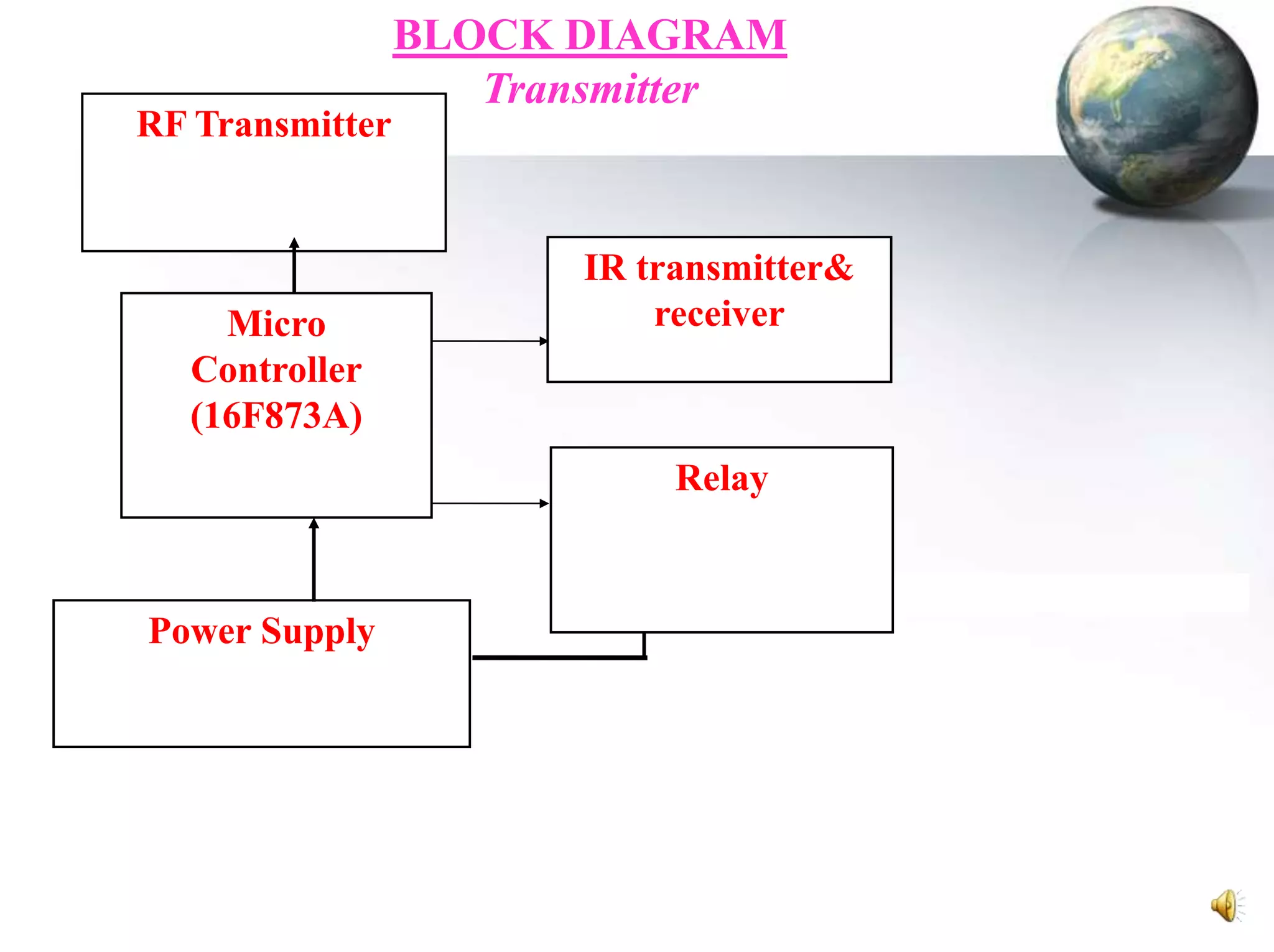
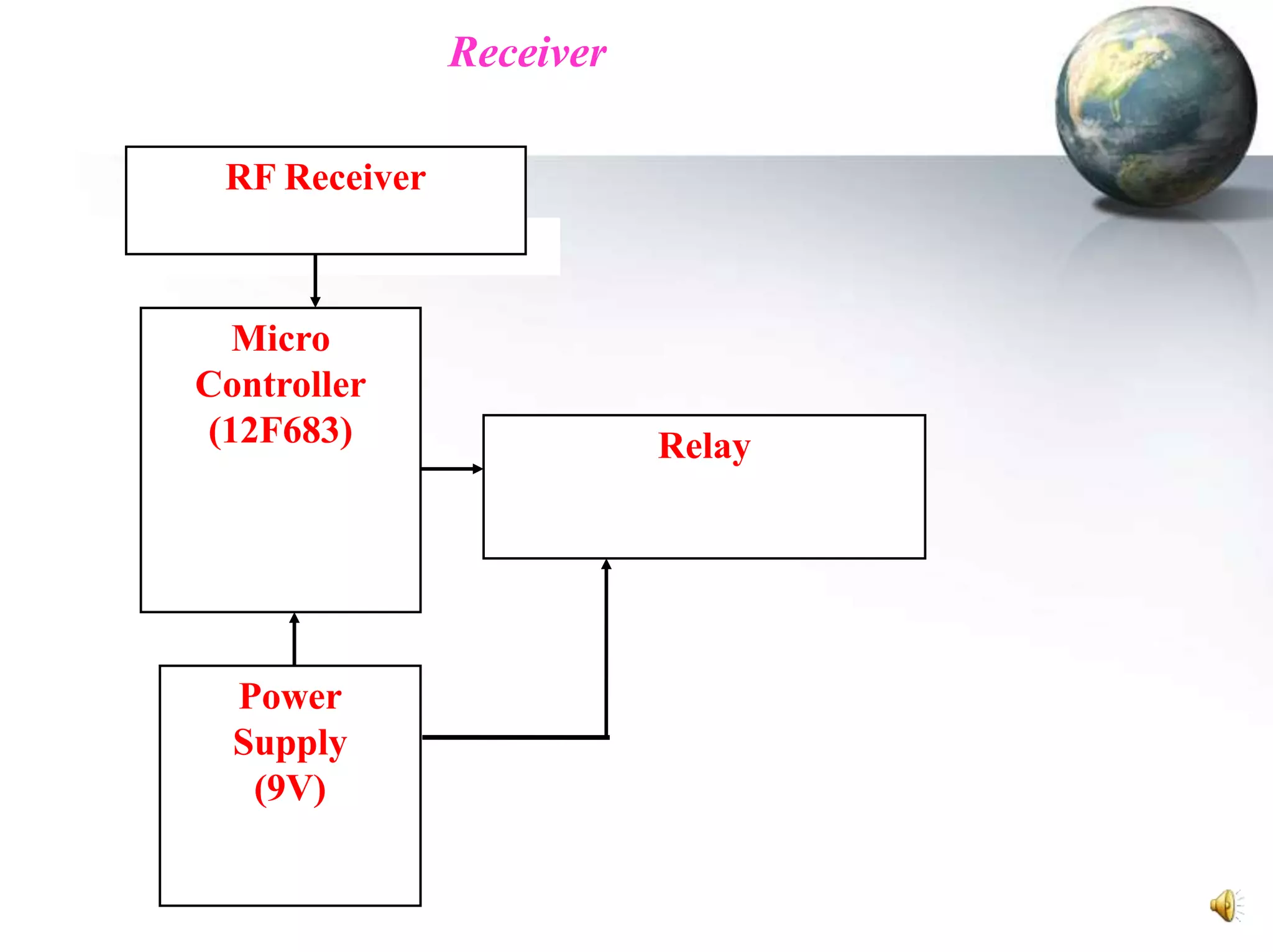
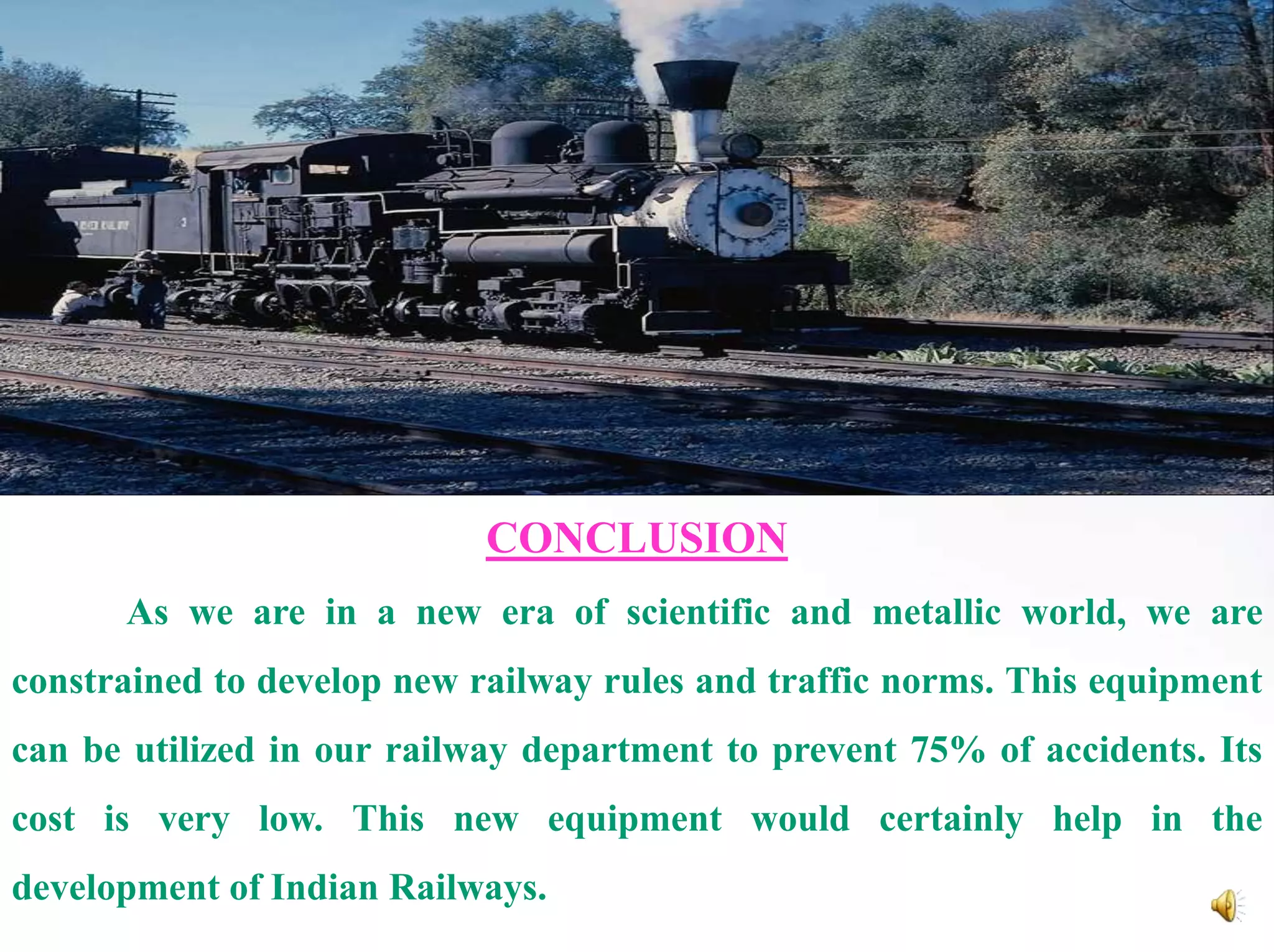
RAILWAY LEVEL CROSSING
ACCIDENTS PREVENTER

Submitted by

S.SAHAYA JUSTUS ANTONY
BIO-DATA
1. NAME
2. AGE & DATE OF BIRTH
3. CLASS
4. COLLEGE ADDRESS

5. PRESENT ADDRESS

6. CONTACT NUMBER
7. E-mail ID

: S.SAHAYA JUSTUS ANTONY
: 19(02.05.1995)
: IInd Year Mechanical
: Cape Institute of Technology,
Levengipuram, Kanyakumary District,
Tamilnadu,India.
: S/o. M.SAHAYADHAS,
Old No: 6.206, New No: 9,
Tsunami Colony, Manakudy,
Kanyakumary District,
Tamilnadu, India, Pin: 629 602.
: 7639837638
: justony2020@gmail.com
DECLARATION

I declare that this project titled “RAILWAY LEVEL
CROSSING ACCIDENTS PREVENTER” is an original
work piece of my own imagination and innovation.
S.SAHAYA JUSTUS ANTONY
TABLE OF CONTENTS
S.No.

TITLE

1.

ABSTRACT

2.

INTRODUCTION

3.

BLOCK DESCRIPTION

4.

LIST OF FIGURES

6.

CONCLUSION
APPENDICES
ABSTRACT
Railway Level Crossing Accidents Preventer is an exiting research in

the railway department which provides safety and prevents the accidents in
the nation.
The main objective of this project is to fabricate a fully automated manned
& unmanned railway crossing. In this project, the sensor checks the train
before reaching the level crossing from a particular distance depending on
the capacity of the sensor and gives a command to the receiver units.
When a train approaches the level crossing an alarm sound is produced
and the RED light displayed. At that time our device fixed vehicles that is
nearing the level crossing will receive the message and will be stopped.
Similarly after the train crosses the level crossing, the sensor senses the
train has crossed the level crossing, and gives a command to the receiver
units. Now the alarm stops and the GREEN light glows and the signal allows
the vehicles to moves on.
INTRODUCTION
This project is used to Control the Vehicles on the Manned &
Unmanned Railway crossing area. RF concept is used in this project. PIC
Microcontroller is used to detect the signal when the train is near the
railway crossing at that time our device fixed vehicles will be stopped.
The IR Sensor is used in the area of the Railway Track. The signals
always pass through the other IR Sensors fitted in the vehicle. If the train
comes near our sensors, The Transmitter detects the Signals and sends the
data to the receiver module fitted in the vehicle. At the same time the Red
signal is displayed (ie ON) in the traffic signal pole. The Green signal (ie
OFF) is dormant and alarm sound produced and then the counter will be
ON.
When the Receiver module fixed in the vehicle receives the transmitter
data, the approaching vehicle stops quickly. In the mean time the train
crosses the other IR Sensors. The Transmitter detects the signals and sends
the data to the receiver module of the vehicle. At the same time the GREEN
light glows and signals the approaching vehicle to cross the railway track.
The RED signal light goes to OFF position. The receiver module receives the
transmitter data and the vehicle safely passes through the railway track.
BLOCK DESCRIPTION
The embedded based Automatic Signal Detector System using serial
communication has various blocks in it. The following are the various units
in it.

1. Power Supply.
2. Microcontroller unit.
3. RF transmitter Unit.

4. RF receiver unit.
1. Power Supply:
The input to the power supply unit is AC 230v, 50Hz. The rectifier in

the circuit converts the AC into DC and the regulator IC 7805 is used to
generate 5 volt to the remaining units.
2. Microcontroller:
The controller is the heart of the system. This project has two controllers,
one at RF transmitter side and other at RF receiver side. It controls all the
operations of the various blocks. It is an 8 bit controller, which process only
8 bit at a time. All the blocks are interfaced with the controller through its
ports. The input signal is processed by the controller in the transmitter side
and displays the output on the LED display connected in RF receiver side.
The controller reads the signal from the voice chip and processes it.
3. RF Transmitter Unit:
The operating frequency of the RF transmitter is 433.92 MHz. the baud
rate of the RF transmitter is 4800bps. The RF is based on SAW architecture
with minimum range of 100 feet. No external component is required. It has
good signal to noise ratio with low power consumption.
The data will be transmitted by the RF transmitter to the RF receiver
unit. The RF transmitter is connected to the transmitter (Tx) of the
controller.
4. RF Receiver Unit:
The RF receiver unit works with frequency of 433 MHz. the baud
rate of the circuit is 4800bps. The same SAW architecture is used in the
receiver module. It is connected to the receiver (Rx) pin of the controller.

The received parameters are processed by the controller and it displays
the parameters on the display unit.
LIST OF FIGURES
S.No

TITLE

1.

Proposed Model

2.

Layout Diagram

3.

Block Diagram
*Transmitter
*Receiver
PROPOSED MODEL
RF Transmitter

Micro
Controller
(16F873A)

BLOCK DIAGRAM
Transmitter

IR transmitter&
receiver

Relay

Power Supply
Receiver
RF Receiver

Micro
Controller
(12F683)

Power
Supply
(9V)

Relay
CONCLUSION
As we are in a new era of scientific and metallic world, we are
constrained to develop new railway rules and traffic norms. This equipment
can be utilized in our railway department to prevent 75% of accidents. Its
cost is very low. This new equipment would certainly help in the
development of Indian Railways.
LIST OF SIGNIFICANT COLLISIONS
Level crossings present a significant risk of collisions between trains and road
vehicles. This list is not a definitive list of the world's worst accidents.
Accident
Langenweddingen level crossing disaster
Nagpur level crossing disaster

Deaths
94
55

Country
Germany
India

Year
1967
2005

Marhanets train and bus collision

45

Ukraine

2010

Polgahawela level crossing accident

35

Sri Lanka

2005

Lake Balaton level crossing disaster, Siófok

33

Hungary

2003

Xirivella level crossing accident, Valencia

27

Spain

1980

Dorion level crossing accident

19

Canada

1966

2009 Slovak coach and train collision

12

Slovakia

2009

Bourbonnais train accident

11

United States

1999

Hixon rail crash
Glendale train crash
Kerang rail accident
Lockington rail crash
Gerogery level crossing accident

11
11
11
9
5

United Kingdom
United States
Australia
United Kingdom
Australia

1968
2005
2007
1986
2001

Fox River Grove level crossing accident

7

United States

1995

Ufton Nervet rail crash

7

United Kingdom

2004
THANK YOU TO ALL

RAILWAY LEVEL CROSSING ACCIDENTS PREVENTER - SAHAYA JUSTUS ANTONY.S

  • 1.
    RAILWAY LEVEL CROSSING ACCIDENTSPREVENTER Submitted by S.SAHAYA JUSTUS ANTONY
  • 2.
    BIO-DATA 1. NAME 2. AGE& DATE OF BIRTH 3. CLASS 4. COLLEGE ADDRESS 5. PRESENT ADDRESS 6. CONTACT NUMBER 7. E-mail ID : S.SAHAYA JUSTUS ANTONY : 19(02.05.1995) : IInd Year Mechanical : Cape Institute of Technology, Levengipuram, Kanyakumary District, Tamilnadu,India. : S/o. M.SAHAYADHAS, Old No: 6.206, New No: 9, Tsunami Colony, Manakudy, Kanyakumary District, Tamilnadu, India, Pin: 629 602. : 7639837638 : justony2020@gmail.com
  • 3.
    DECLARATION I declare thatthis project titled “RAILWAY LEVEL CROSSING ACCIDENTS PREVENTER” is an original work piece of my own imagination and innovation. S.SAHAYA JUSTUS ANTONY
  • 4.
    TABLE OF CONTENTS S.No. TITLE 1. ABSTRACT 2. INTRODUCTION 3. BLOCKDESCRIPTION 4. LIST OF FIGURES 6. CONCLUSION APPENDICES
  • 5.
    ABSTRACT Railway Level CrossingAccidents Preventer is an exiting research in the railway department which provides safety and prevents the accidents in the nation. The main objective of this project is to fabricate a fully automated manned & unmanned railway crossing. In this project, the sensor checks the train before reaching the level crossing from a particular distance depending on the capacity of the sensor and gives a command to the receiver units. When a train approaches the level crossing an alarm sound is produced and the RED light displayed. At that time our device fixed vehicles that is nearing the level crossing will receive the message and will be stopped. Similarly after the train crosses the level crossing, the sensor senses the train has crossed the level crossing, and gives a command to the receiver units. Now the alarm stops and the GREEN light glows and the signal allows the vehicles to moves on.
  • 6.
    INTRODUCTION This project isused to Control the Vehicles on the Manned & Unmanned Railway crossing area. RF concept is used in this project. PIC Microcontroller is used to detect the signal when the train is near the railway crossing at that time our device fixed vehicles will be stopped. The IR Sensor is used in the area of the Railway Track. The signals always pass through the other IR Sensors fitted in the vehicle. If the train comes near our sensors, The Transmitter detects the Signals and sends the data to the receiver module fitted in the vehicle. At the same time the Red signal is displayed (ie ON) in the traffic signal pole. The Green signal (ie OFF) is dormant and alarm sound produced and then the counter will be ON.
  • 7.
    When the Receivermodule fixed in the vehicle receives the transmitter data, the approaching vehicle stops quickly. In the mean time the train crosses the other IR Sensors. The Transmitter detects the signals and sends the data to the receiver module of the vehicle. At the same time the GREEN light glows and signals the approaching vehicle to cross the railway track. The RED signal light goes to OFF position. The receiver module receives the transmitter data and the vehicle safely passes through the railway track.
  • 8.
    BLOCK DESCRIPTION The embeddedbased Automatic Signal Detector System using serial communication has various blocks in it. The following are the various units in it. 1. Power Supply. 2. Microcontroller unit. 3. RF transmitter Unit. 4. RF receiver unit. 1. Power Supply: The input to the power supply unit is AC 230v, 50Hz. The rectifier in the circuit converts the AC into DC and the regulator IC 7805 is used to generate 5 volt to the remaining units.
  • 9.
    2. Microcontroller: The controlleris the heart of the system. This project has two controllers, one at RF transmitter side and other at RF receiver side. It controls all the operations of the various blocks. It is an 8 bit controller, which process only 8 bit at a time. All the blocks are interfaced with the controller through its ports. The input signal is processed by the controller in the transmitter side and displays the output on the LED display connected in RF receiver side. The controller reads the signal from the voice chip and processes it. 3. RF Transmitter Unit: The operating frequency of the RF transmitter is 433.92 MHz. the baud rate of the RF transmitter is 4800bps. The RF is based on SAW architecture with minimum range of 100 feet. No external component is required. It has good signal to noise ratio with low power consumption.
  • 10.
    The data willbe transmitted by the RF transmitter to the RF receiver unit. The RF transmitter is connected to the transmitter (Tx) of the controller. 4. RF Receiver Unit: The RF receiver unit works with frequency of 433 MHz. the baud rate of the circuit is 4800bps. The same SAW architecture is used in the receiver module. It is connected to the receiver (Rx) pin of the controller. The received parameters are processed by the controller and it displays the parameters on the display unit.
  • 11.
    LIST OF FIGURES S.No TITLE 1. ProposedModel 2. Layout Diagram 3. Block Diagram *Transmitter *Receiver
  • 12.
  • 14.
  • 15.
  • 16.
    CONCLUSION As we arein a new era of scientific and metallic world, we are constrained to develop new railway rules and traffic norms. This equipment can be utilized in our railway department to prevent 75% of accidents. Its cost is very low. This new equipment would certainly help in the development of Indian Railways.
  • 17.
    LIST OF SIGNIFICANTCOLLISIONS Level crossings present a significant risk of collisions between trains and road vehicles. This list is not a definitive list of the world's worst accidents. Accident Langenweddingen level crossing disaster Nagpur level crossing disaster Deaths 94 55 Country Germany India Year 1967 2005 Marhanets train and bus collision 45 Ukraine 2010 Polgahawela level crossing accident 35 Sri Lanka 2005 Lake Balaton level crossing disaster, Siófok 33 Hungary 2003 Xirivella level crossing accident, Valencia 27 Spain 1980 Dorion level crossing accident 19 Canada 1966 2009 Slovak coach and train collision 12 Slovakia 2009 Bourbonnais train accident 11 United States 1999 Hixon rail crash Glendale train crash Kerang rail accident Lockington rail crash Gerogery level crossing accident 11 11 11 9 5 United Kingdom United States Australia United Kingdom Australia 1968 2005 2007 1986 2001 Fox River Grove level crossing accident 7 United States 1995 Ufton Nervet rail crash 7 United Kingdom 2004
  • 18.