Downloaded 2,509 times
![MAJOR PROJECT SPEED CHECKER ON HIGHWAY
DEPARTMENT OF ELECTRONICS & COMMUNICATION 8
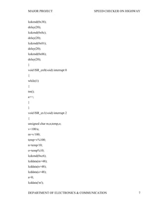
lcddata('m');
lcddata('/');
lcddata('s');
lcddata('e');
lcddata('c');
lcddata(' ');
lcddata(' ');
}
void main()
{
unsigned char w[]="WELCOMESPEED=WAITING...";
IT0 = 1; // Configure interrupt 0 for falling edge on /INT0 (P3.2)
EX0 = 1; // Enable EX0 Interrupt
IT1 = 1; // Configure interrupt 1 for falling edge on /INT0 (P3.2)
EX1 = 1; // Enable EX1 Interrupt
EA = 1; // Enable Global Interrupt Flag
IP=0x04; // Priority of ex1 high
lcd_init();
lcdcmd(0x84);
for(i=0;i<7;i++)
lcddata(w[i]);
lcdcmd(0xc0);
for(i=7;i<13;i++)
lcddata(w[i]);
for(i=13;i<24;i++)
lcddata(w[i]);
while(1);
}
void tm()
{
int y=0;](https://image.slidesharecdn.com/speedchecker-140530020850-phpapp01/85/Speed-checker-on-highway-using-8051-8-320.jpg)
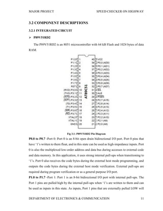
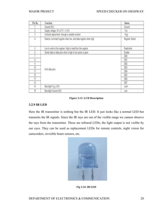
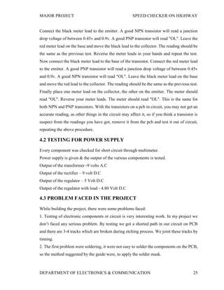

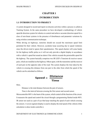
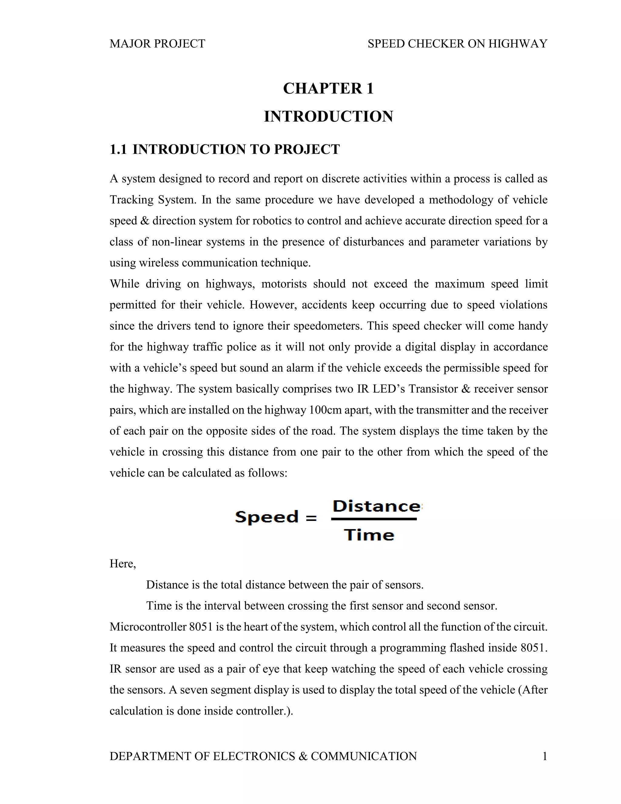
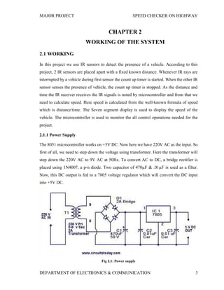
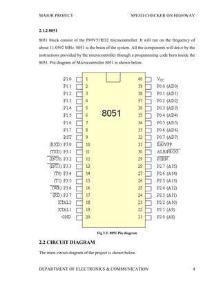
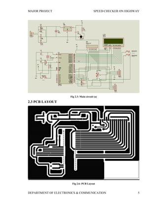
The document describes the development of a vehicle speed and direction monitoring system designed for highway use, employing infrared sensors to accurately measure vehicle speed and alert drivers if they exceed the speed limit. The system uses an 8051 microcontroller to process data from sensors placed 100 cm apart, calculating speed based on the time taken to cross this distance. Additionally, the project outlines the components used, including power supply considerations and circuit layout.