Downloaded 43 times

![This has also come under threat with some customers
wanting SCADA data to travel over their pre-established
corporate networks or to share the network with other
applications. The legacy of the early low-bandwidth
protocols remains, though. SCADA protocols are designed
to be very compact and many are designed to send
information to the master station only when the master
station polls the RTU. Typical legacy SCADA protocols
include Modbus RTU, RP-570, Profibus and Conitel. These
communication protocols are all SCADA-vendor specific but
are widely adopted and used. Standard protocols are IEC
60870-5-101 or 104, IEC 61850 and DNP3. These
communication protocols are standardized and recognized
by all major SCADA vendors. Many of these protocols now
contain extensions to operate over TCP/IP. It is good
security engineering practice to avoid connecting SCADA
systems to the Internet so the attack surface is reduced.
RTUs and other automatic controller devices were being
developed before the advent of industry wide standards for
interoperability. The result is that developers and their
management created a multitude of control protocols.
Among the larger vendors, there was also the incentive to
create their own protocol to "lock in" their customer base.
A list of automation protocols is being compiled here.
Recently, OLE for Process Control (OPC) has become a
widely accepted solution for intercommunicating different
hardware and software, allowing communication even
between devices originally not intended to be part of an
industrial network.
DESIGN MODULES
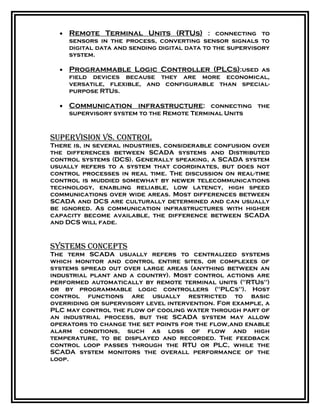
1] adC interfaCe
Analog to digital converters sense a voltage and
convert it into its corresponding digital
representation, based on the percentage of the full
range of the input. For an 8-bit A/D, there are 256
discrete representations of the input voltage. In other
words, it takes the input voltage range and divides it
into 256 equal parts. If, for instance, your input range
was 0 to 2.56 volts, the smallest increment the A/D can
measure is 2.56/256 or 10 mV. Since most micro
controllers operate with 8 bits, using an 8 bit A/D
works out well.
2] rfreCeiver](https://image.slidesharecdn.com/03scada-150305121205-conversion-gate01/85/03-scada-synopsis-7-320.jpg)
![The RF RECEIVER modulates the digital data an
RECEVER FROM TX.
3] rftransmitter
The RF transmitter modulates the digital data and
send to the PC. It’s transmission frequency
315MHZ.
Technical specification
915 MHz (70 cms pan-Euro pean ISM allocation)
75E antenna connection
RF output power programmable in 10 steps between
l.mWand 10 mW
Range 250 m line of sight (LOS) or 30 m in buildings
Data speed on host link: 2.4 to 38.4 kbits/s, adjustable
in
five steps
Fixed 19.2 kbits/s data speed on RF link
Two hardware handshaking signals
RSSI (received signal strength) analogue output
Supply voltage 3.3 V to 5.5 V
a dot-matrix liquid crystal display are internally
provided on one chip, a minimal system can be interfaced
with this controller/driver. A single HD44780U can
display up to one 8-character line or two 8-character
lines.
Analog inputs
Voltage range - 0 - 5V
Resolution - 8 / 10 bits
Conversion time - 100uS
Total access time - 21uS + 10 I/O clock periods
Input resistance - typically >100M
Advantages](https://image.slidesharecdn.com/03scada-150305121205-conversion-gate01/85/03-scada-synopsis-8-320.jpg)


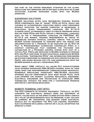
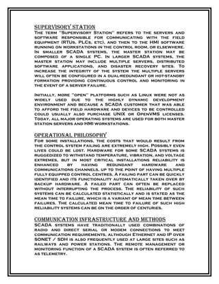
SCADA (Supervisory Control and Data Acquisition) is an industrial control system that monitors and controls a variety of processes including industrial, infrastructure, and facilities-based operations. It encompasses components such as Human-Machine Interfaces (HMIs), supervisory control systems, remote terminal units (RTUs), and communication infrastructure, enabling centralized oversight of operations across vast areas. The adoption of distributed control systems (DCS) within SCADA is evolving, facilitated by advancements in communication technologies that blur the lines between SCADA and DCS functionalities.


