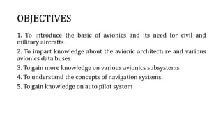
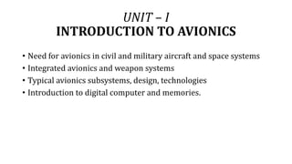
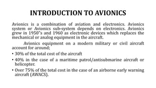
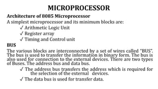
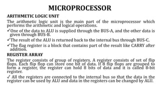
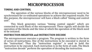
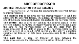
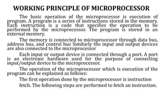
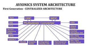
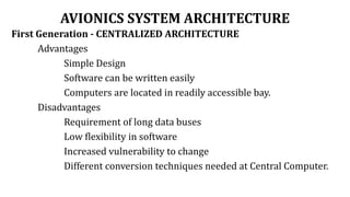
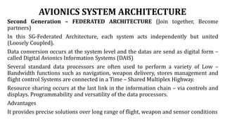
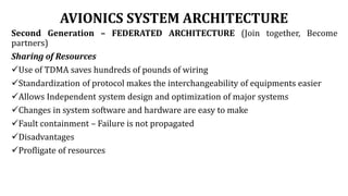
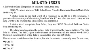
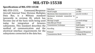
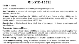
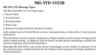
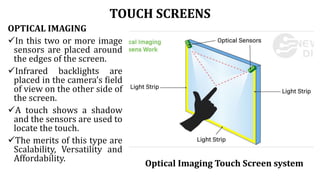
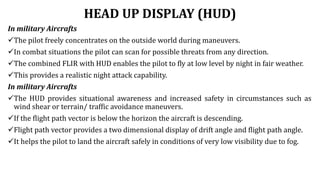
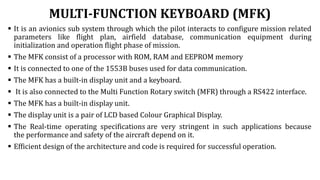
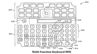
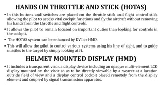
AE8751 / CAE 347
AVIONICS
Mr. NATESAN M
Assistant Professor
Department of Aeronautical Engineering
Dhanalakshmi Srinivasan College of Engineering & Technology
Mamallapuram – 603 104
OBJECTIVES
1. To introduce the basic of avionics and its need for civil and
military aircrafts
2. To impart knowledge about the avionic architecture and various
avionics data buses
3. To gain more knowledge on various avionics subsystems
4. To understand the concepts of navigation systems.
5. To gain knowledge on auto pilot system
UNIT – I
INTRODUCTION TO AVIONICS
• Need for avionics in civil and military aircraft and space systems
• Integrated avionics and weapon systems
• Typical avionics subsystems, design, technologies
• Introduction to digital computer and memories.
INTRODUCTION TO AVIONICS
Avionics is a combination of aviation and electronics. Avionics
system or Avionics sub-system depends on electronics. Avionics
grew in 1950‟s and 1960 as electronic devices which replaces the
mechanical or analog equipment in the aircraft.
Avionics equipment on a modern military or civil aircraft
account for around;
• 30% of the total cost of the aircraft
• 40% in the case of a maritime patrol/antisubmarine aircraft or
helicopter.
• Over 75% of the total cost in the case of an airborne early warning
aircraft (AWACS).
INTRODUCTION TO AVIONICS
Are the electronic systems used on aircraft artificial satellites, and
spacecraft which is a Combination of aviation and electronics
Avionic systems include communications, navigation, the display
and management of multiple systems, and the hundreds of systems
that are fitted to aircraft to perform.
Individual functions. These can be as simple as a searchlight for
helicopter or as complicated as the tactical system for an airborne
early warning platform. Avionics system or Avionics sub-system
dependent on electronics Avionics industry- a major multi-billion
dollar industry worldwide Avionics equipment on a modern
military or civil aircraft account for around 30% of the total cost of
the aircraft.
INTRODUCTION TO AVIONICS
All electronic and electromechanical systems and subsystems (hardware
and software) installed in an aircraft that are dependent on flight crew to carry
out the aircraft mission safely and to meet the mission requirements with
minimum flight crew.
Flight management system (FMS)
Outputs from the GNSS sensors, air data sensors and other on-board
sensors are used by FMS to perform the necessary navigation
calculations and provide information to the Flight crew via a range of
display units.
The flight management system provides the primary navigation, flight
planning, and optimized route determination and en route guidance for
the aircraft and is typically comprised of the following interrelated
functions: navigation, flight Planning, trajectory prediction,
performance computations, and guidance.
To accomplish these functions the flight management system must
interface with several other avionics systems.
NEED FOR AVIONICS
To enable the flight crew to carry out the aircraft mission safely
and efficiently. For civil airliner the mission is carrying passengers
to their destination.
For military aircraft the mission is intercepting a hostile aircraft,
attacking a ground target, reconnaissance or maritime patrol.
Advantages
Increased safety
Air traffic control requirements
All weather operation
Reduction in fuel consumption
Improved aircraft performance and control and handling and
reduction in maintenance costs
Need for Avionics in Civil and Military
Aircraft and Space Systems
Need for avionics in Civil Aircraft systems
I) For Mission and Management computation
2) For getting the magnetic field thru Magnetometer
3) For various Payloads and Data-link Control through extended
1/0
4) Reduce the crew workload
5) By Avionics in Civil Aircrafts, aircraft mission carried safely
and efficiently.
6) By All Weather operation thru avionics reduce the
maintenance cost of aircraft
Need for Avionics in Civil and Military Aircraft
and Space Systems
Need for avionics in Civil Aircraft systems
7) For better flight control, performing computations and
increased control over flight control surfaces. (PWM)
8) For navigation, provide information using sensors like
Altitude and Head Reference System (AHRS).
9) Provide air data like altitude, atmospheric pressure,
temperature, etc.
10) Increased safety for crew and passengers.
11) Reduction in aircraft weight which can be translated into
increased number of passengers or long range.
Need for Avionics in Civil and Military
Aircraft and Space Systems
Need for Avionics in Space Systems
• Thru Avionics, excellent Sensors used around the spacecraft for
data acquisition.
• Redundancy system and autopilot are the needs using Avionics
in Space systems
• Fly-by-wire communication system used for space vehicle's
attitude and translation control.
• Autopilot redundancy system.
• On-board computers used in satellites for processing the data.
Need for Avionics in Civil and Military
Aircraft and Space Systems
Need for avionics in Military Aircraft systems
• Avionics in fighter aircraft eliminates the need for a second
crew member like navigator,
• observer etc., which helps in reducing the training costs.
• A single seat fighter is lighter and costs less than an equivalent
two seat version.
• Improved aircraft performance, control and handling.
• Reduction in maintenance cost.
• Secure communication.
Need for Avionics in Civil and Military
Aircraft and Space Systems
Need for avionics in Military Aircraft systems
• IN THE MILITARY CASE
✓ A single seat fighter or strike (attack) aircraft is lighter
✓ Costs less than an equivalent two seat version
✓Elimination of the second crew member
(navigator/observer/crew member)
✓ Reduction in training costs
Integrated Avionics and Weapon
Systems
Integrated avionics means different things to different people.
• To the pilot, it means all the information is coordinated and
available from a single source.
• To the software engineer, it means access to shared data
about the situation, the mission, and the aircraft systems.
• To the hardware designer, it means common modules in a
single backplane with the connectivity and bandwidth to
support the required processing.
Integrated Avionics and Weapon
Systems
Integrated Avionics and Weapon Systems
Advantages of integrated Avionic System:
I. Advanced flight deck functions
2. Improved situational awareness to Pilot
3. Increased system flexibility for business and regional aircrafts.
4.Large Liquid Crystal Flat Panel Displays
5. Integrated Navigation
6. Quick Modification of Flight Plans for sudden change in weather,
Terrain and Air Traffic.
7. Control of Cock Pit lnfo and Display lnfo
8. Integration with subsystems in the aircraft
Integrated Avionics and Weapon Systems
Other features of Integrated Avionics
• Electronic Warfare
• Stores Management System
• Inertial Reference System with GPS
• Software providing 1.7 million lines of code
• Liquid flow through cooling lending to an mean time between
failures (MTBF) of 25,000 hours
• Power Supply modules cooled with polyalphaolefin (PAO) liquid
coolant to carry away heat generated by the supplies' power-
conversion process
Integrated Avionics and Weapon Systems
Integrated Avionics Weapon Systems:
• SONAR
• RADAR
• Military communications
• Electro optics (FUR or PIDS)
• ECMOR ECCM – Electronic Counter-Counter Measure
• ESM/DAS – Electronic Support Measure / Distributed
Aperture System
• Tactical missile guidance
Integrated Avionics and Weapon Systems
Integrated Weapon System:
• Consisting of AIM-9 air-to-air missile fired with F-22
maneuvering 60 degrees Rolling per second
• All 52 missile tests prior to IOT&E complete
• First JDAM separation test complete
• Successful Gun system tests
• Certified Chaff and flare counter measures
Integrated Avionics and Weapon Systems
The Avionics and Weapon System (AWS) in any modern day fighter
aircraft enables the pilot to perform various mission functions.
(i) Receive Inputs from sensors, communication systems,
Radio navigation systems, Identification system,
Missiles, Electronic counter measures system, Pilot
controls.
(ii) Computation of required parameters for Navigation
and Fire control.
(iii) Transferring the computed results to displays, Audio
system and weapons.
(iv) Controlling of weapon launch / Firing.
(v) Control / Co-ordinate / manage sensors optimally.
Sensors
A device which detects or measures a physical property and
records, indicates, or otherwise responds to it. like, Radars, Inertial
Navigation System, Air Data System, Forward Looking Infrared
Sensor, etc,.
Communication Systems
It is a digital datalink system for transmission of short
messages between aircraft and ground stations via airband radio or
satellite. Data Link, Voice Link
Radio Navigation System
Tactical Air Navigation (TACAN) is a Ultra High Frequency
Navigation system.
Identification System
Identification Friend or Foe (IFF) is designed for command
and control. It identifies the friendly targets but not hostile ones.
Missiles: Locked on to target
Electronic Counter Measures Systems
Radar warning receiver, Self-protection jammer, Offensive
jammer.
Self Protection Jammer – It is used to prevent detection by enemy
radar by jamming the signal of hostile radar.
Pilot Controls
Hands on stick and throttle controls
Parameters for Navigation and Fire control
Navigation Algorithms – Guidance to steer point
Fire Control Algorithms – Weapon Aiming, Missile Launch
Control Weapon Launch / Firing
Weapon selection and preparation, launch sequence and jettison
(throw or drop from the aircraft).
CORE AVIONICS
SYSTEMS
A hierarchical structure
comprising layers of specific
task and avionics system
function for enabling the
crew to carry out the aircraft
mission.
In the core avionics system,
the systems which directly
interface with pilot are given.
Display System
It provides the visual interface between the pilot and the aircraft
systems.
Types
• HUD - Head Up Displays
• HMD - Helmet Mounted Displays
• HDD – Head Down Displays
Data Entry and Control System
It is essential for the crew to interact with the avionic system. Ex:
Keyboards, Touch Panels to use direct voice Input, Voice warning
systems and so on.
Air Data System
1. Indicate Pr,
2. Altitude,
3. Speed,
4. Mach Number,
5. State Air Temp etc thru a computer called ADC
Air Data System
1. Indicate Pr,
2. Altitude,
3. Speed,
4. Mach Number,
5. State Air Temp etc thru a computer called ADC
Communication System
It provides the two way communication between the ground bases
and the aircraft or between aircrafts. A Radio Transmitter and
Receiver was the first avionics system installed in an aircraft. The
different types of frequencies used for several ranges are given
below.
• Long Range Communication – High Frequency (2 – 30 MHz)
• Medium Range Communication – Very High Frequency (30 – 100
MHz)
• Military Aircraft – Ultra High Frequency (250 – 400 MHz)
Now a days satellite communication systems are used to provide
very reliable communication.
Flight Control System
It uses the electronic system in two areas.
(i) Auto Stabilization
• Roll Auto Stabilizer System
• Pitch Auto Stabilizer System
(ii) FBW Flight Control Systems
It provides continuous automatic stabilization of the aircraft by
computer control of the control surfaces from appropriate motion
sensors.
1. Means Fly by wire and Fly by Light -two methods in Flight Control
system
2. Include automatically controlling flight using auto-pilots Scheme to
control heading and altitude and for Auto stabilization-AFC
3. Limited authority on thrust and flight control surfaces
ILS
Instrument Landing Systems or Microwave Landing System is used
for approach guidance to the airfield.
Aircraft State Sensor Systems
For control and navigation of the aircraft the air data quantities are
essential.
Air Data Quantities are,
✓ Altitude
✓ Calibrated Airspeed
✓ Vertical speed
✓ True Airspeed
✓ Mach Number
✓ Airstream Incidence Angle.
The air data computing system computes these quantities
from the outputs of sensors which measure the static and total
pressure and the outside air temperature.
Navigation System
The Navigation system provides Navigation Information (Aircraft’s
position, Ground speed, Track angle).
✓ Dead Reckoning Systems
✓ Position Fixing Systems
DR Navigation systems derive the vehicle’s present position
by estimating the distance travelled from a known position from
knowledge of the speed and direction of the vehicle.
Types of DR Navigation systems are,
i) Inertial Navigation systems (Most Accurate)
ii) Doppler / Heading Reference Systems (Used in Helicopters)
iii) Air Data / Heading Reference Systems (Low Accuracy when
compared to the above systems)
Navigation System
A. By Very High Frequency Omni directional Range or Distance
Measuring Equipment DME
B. By Satellite Based Navigation by MEO Satellites at 1575 MHz
Satcom via the lnmarsat satellites using 4 Satellites centralized over
the Pacific Ocean, Indian Ocean, Atlantic Ocean-East, and Atlantic
Ocean-West for high altitudes
C. Ground Based Navigation using LOS by VOR/DME having B-Nav
and P-nav where the track accuracy is within +/- 5 nm and +/-1 nm
D. Use VOR for getting the navigation track from many ground
stations between Aircraft and ATC through VHF Freq. (108.1
through 117.95 MHz)
E. Satellite Based Navigation by OPS on 1575 MHz
Radio Navigation Systems: (Position Fixing Systems)
Satellite or ground based transmitter is used to transmit the
signal and it was received by the receiver in the aircraft. According
to the received signals a supporting computer is used to derive the
aircraft’s position. The Prime Position Fixing System used in aircraft
is GPS.
Outside World Sensor Systems
These systems comprise both radar and infrared sensor
which enables all weather and night time operation.
Radar Systems
Weather Radar detects water droplets, cloud turbulence and
warning about storms.
Fighter Aircrafts Radars
Multi Mode Radars for ground attack role and interception role. The
Radar must be able to detect aircraft upto 100 miles away and track
several aircraft simultaneously (12 aircraft’s). The Radar must have
a look down capability to track low flying aircraft below it.
Infrared Systems
It is used to provide a video picture of the thermal image scene of
the outside world by using fixed Forward Looking Infra Red (FLIR)
sensor or a gimbaled IR imaging sensor. The thermal image picture
at night looks similar to the visual picture in day time, but highlights
heat sources such as vehicle engines. FLIR can also be installed in
civil aircraft to provide enhanced vision in addition with HUD.
Navigation Management System
It comprises the operation of all radio navigation aid systems
and the combination of data from all navigation sources such as GPS
and INS systems, to provide the best estimation of the aircraft
position and ground speed.
Engine Control and Management
Modern jet engines are having the Full Authority Digital
Engine Control System (FADEC). This controls flow of fuel. This
control system ensures the engine’s temperature, speed and
acceleration in control.
Engine health monitoring system record a wide range of
parameters, so it will give early warning of engine performance
deterioration, excessive wear, fatigue damage, high vibrations,
excessive temperature etc.,
Autopilots and Flight Management Systems
The autopilot relieves the pilot in long range mission. FMS
came into use in 1980‟s (Civil Aircraft).
The FMS tasks are given below.
(i) Flight Planning
(ii) Navigation Management
(iii) Engine control to maintain the planned speed
(iv) Control of Aircraft Flight Path
(v) Minimizing Fuel consumption
(vi) Ensuring the aircraft is at the planned 3D position at the
planned time slot (for Air Traffic Control).
House Keeping Management
Automation of the background task which are essential for the
aircraft’s safe and efficient operation.
Background tasks include
i) Fuel management
ii) Electrical power supply management
iii) Hydraulic power supply management
iv) Cabin / Cockpit pressurization systems
v) Environmental control systems
vi) Warning systems
vii) Maintenance and monitoring systems
AVIONICS SYSTEM DESIGN
Starting point for designing a digital avionics system is a clear
understanding of the mission requirements.
The three stages of avionics system design are:
Conceptual design
Preliminary design
Detailed design
Conceptual design considerations are,
What will it do?
How will it do it?
What is the general arrangement of parts?
AVIONICS SYSTEM DESIGN
The end result of conceptual design is an artist’s or engineer’s
conception of the vehicle/product.
Example: Clay model of an automobile.
Preliminary design considerations are,
How big will it be?
How much will it weight?
What engines will it use?
How much fuel or propellant will it use?
How much will it cost?
This is what you will do in this course.
AVIONICS SYSTEM DESIGN
Detailed design considerations are,
How many parts will it have?
What shape will they be?
What materials?
How will it be made?
How will the parts be joined?
How will technology advancements (e.g. lightweight material,
advanced airfoils, improved engines, etc.) impact the design?
DESIGN and TECHNOLOGY
Specific things to be considered while designing an Avionics Systems
are,
(i) Functional Requirements
(ii) Cost
(iii) Required Safety level
(iv) Selection of Design
- Allocation of functions to sub-systems
- Identification of failure modes and its effects
(v) Implementation, Testing and Evaluation
(vi) Validation
DESIGN and TECHNOLOGY
(vii) Reliability
(viii) Flexibility
(ix) Weight
(x) Power
Major Design aspects are,
a) Basic Architecture
b) Inter system communication
c) Incorporation of fault tolerant system
d) Evaluation of system design
System Architectures
i) Centralized
Signal conditioning and computations are done by computers in an
avionics bay and the signals are transmitted over one way data bus.
• Advantages
Simple design, Software can be written easily.
• Disadvantages
Long data buses are required, Possibility for damage.
ii) Federated
Sharing of input, sensor data and computed results over data buses.
iii)Distributed
Multiple processors are used for computing the task under real time
basis. This Architecture is used in modern avionics system.
APPLICATION OF AVIONICS SYSTEM DESIGN TECHNOLOGY
Example: Top-level Requirement for Military Purpose
The customer prepares the statement of need and top level
description of possible missions which describes the gross
characteristic of a hypothetical aircraft that could fly the mission.
Customer may also describe the mission environment and define
strategic and tactical philosophies and principles and rules of
engagement. The system development cycle and the Aircraft Mission
Requirements to Avionics System
• Figure1.2 System Development Cycle
Fig 1.3 Aircraft Mission Requirements to Avionics System Requirements
“ILITIES” OF AVIONICS SYSTEM
Ilities - An abstract quality that good software should exhibit.
•Capability
• Reliability
• Maintainability
• Certificability
• Survivability(military)
• Availability
• Susceptibility
• vulnerability
• Life cycle cost(military) or cost of ownership(civil)
• Technical risk
• Weight and power
“ILITIES” OF AVIONICS SYSTEM
Capability
Whether the avionics system is capable?
Can they do the job and even more?
Designer to maximize the capability of the system within the
constraints that are imposed.
Reliability
The ability of a system or component to perform its required
functions under stated conditions for a specified time.
Designer strives to make systems as reliable as possible.
High reliability less maintenance costs.
If less reliable customer will not buy it and in terms of civil airlines
the certificating agencies will not certify it.
“ILITIES” OF AVIONICS SYSTEM
Maintainability
Closely related to reliability.
Maintainability is defined as the probability of performing a
successful repair action within a given time.
System must need preventive or corrective maintenance.
System can be maintained through built in testing,
automated troubleshooting and easy access to hardware.
Availability
Combination of reliability and maintainability.
Trade of between reliability and maintainability to optimize
availability.
Availability translates into sorties for military aircraft and into
revenue flights for civil aircrafts.
“ILITIES” OF AVIONICS SYSTEM
Certificability
Major area of concern for avionics in civil airlines.
Certification conducted by the regulatory agencies based on detailed,
expert examination of all facets of aircraft design and operation.
The avionics architecture should be straight forward and easily
understandable.
There should be no sneak circuits and no obvious modes of operation.
Avionics certification focus on three analyses: preliminary hazard, fault
tree, and FMEA.
Risk
Amount of failures and drawbacks in the design and implementation.
Overcome by using the latest technology and fail proof technique to
overcome both developmental and long term technological risks.
“ILITIES” OF AVIONICS SYSTEM
Survivability
It is a function of susceptibility and vulnerability.
– Susceptibility: measure of probability that an aircraft will be hit by a given
threat.
– Vulnerability: measure of the probability that damage will occur if there is a hit
by the threat
– Life Cycle Cost(LCC)or Cost of ownership:
• It deals with economic measures need for evaluating avionics architecture.
• It includes costs of varied items as spares acquisition, transportation,
storage and training (crew and Maintenance personnel's), hardware
development and test, depreciation and interest
Weight and power
 Minimize the weight and power requirements are two fundamental concepts of
avionics design.
So the design must be light weight and power consuming which is possible
through the data bus and latest advancement of electronics devices.
Introduction to Digital Computer and Memories
Digital number system- number systems and codes - Fundamentals
of logic and combinational logic circuits, Microprocessors,
Memories, Digital Computers
NUMBER SYSTEM
Number system is a basis for counting various items. Modern
computers communicate and operate with binary numbers which
use only the digits 0 and 1.
Decimal number system
In decimal number system we can express any decimal
number in units, tens, hundreds, and thousands and so on. When,
we write a decimal number say, 5678.9. It can be represented as
5000+600+70+8+0.9 = 5678.9
The decimal number 5678.9 can also be written as 5678.910, where the 10 subscript
indicates the radix or base. Decimal system with its ten digits is a base-ten system.
Example:
5678.910 = 5x10³ + 6x10² + 7x101 + 8x100 + 9x10⁻¹
Binary number system
Binary system with its two digits is a base-two system. The two binary digits
(bits) are 1 and 0.In binary system each binary digit commonly known as bit has its
own value or weight. However in binary system weight is expressed as a
power of 2. Example:
5678.92 = 5 x 23 + 6 x 22 + 7 x 21 + 8 x 20 + 9 x 2-1
Octal number system
The octal number system uses first eight digits of decimal number system: 0, 1,
2, 3, 4, 5, 6 and 7. As its uses 8 digits, its base is 8. Example:
5678.98 = 5 x 83 + 6 x 82 + 7 x 81 + 8 x 80 + 9 x 8-1
Hexadecimal number system
The hexadecimal number system has a base of 16 having16 digits: 0, 1, 2, 3, 4, 5,
6, 7, 8, 9, A, B, C, D, E and F. Example:
3FD16 = 3 x 162 + F x 161 + D x 160
NUMBER SYSTEM CONVERSION
1. Binary to Octal Conversion
The base for octal number is the third power of the base for binary
numbers. Therefore, by grouping 3 digits of binary number and then converting
each group digit to its octal equivalent.
Example: (11101100)2 = 111 101 100 = Octal number = (754)8
7 5 4
2. Octal to Binary Conversion
Conversion from octal to binary is a reversal of the process of octal to binary
conversion.
Example: (754)8 = 7 5 4 = Binary number = 111 101 100
111 101 100
STUDY OF BASIC GATES
The basic elements that make a digital system are logic gate. The most common
gates are NAND, OR, NOR, AND, EXOR, EXNOR gates. The NAND and NOR gates
can implemented using NOT, AND and OR gates. A simple logic element whose
binary output in a Boolean function (AND, OR.......) of the input is known as gates.
AND GATE
In AND gate the output Y is product of two inputs A and B. Hence even if
one input is zero, the output becomes zero. If both input signals are equal
to one then the output is also one.
Y=A.B
OR GATE
In the OR gate the output Y is sum of two inputs A and B. Hence even if
anyone of input is one or both input are one then output becomes one. The
output becomes zero only when both inputs are zero.
Y=A+B
NOT GATE
The NOT gate performs the basic function called inversion or
complementation. The purpose of this gate is to convert one logic level into
opposite logic level. It has one input and one output. When a high level is
applied to an inverter, a low level appears at its output and vice versa.
Y= -A.
NAND GATE
NAND gate is construction of NOT & AND gate. It has two or more input
and only one output. When inputs are HIGH, the output is LOW. If any one
or both input is LOW, then the output is HIGH. The smallest circle or
bubble represents the operation of inversion.
Y= -(A.B)
NOR GATE
NOR is construction of NOT-OR gates. It has two or more inputs and one
output. The output is HIGH only when all the input is LOW. If both inputs
are HIGH then output is low. The small circle or bubble represents the
operation of inversion.
Y= -(A+B)
EX-OR GATE
An exclusive OR gate is a gate with one or more inputs and one output. In
two input EX-OR gate, if both inputs A and B same (00 or11) means the
output is always HIGH. For other inputs the output will be LOW.
Y= (-AB+A-B)
MICROPROCESSOR
Architecture of 8085 Microprocessor
A simplest microprocessor and its minimum blocks are:
✓ Arithmetic Logic Unit
✓ Register array
✓ Timing and Control unit
BUS
The various blocks are interconnected by a set of wires called “BUS”.
The bus is used to transfer the information in binary form. The bus is
also used for connection to the external devices. There are two types
of Buses. The address bus and data bus.
✓ The address bus transfers the address which is required for
the selection of the external devices.
✓ The data bus is used for transfer data.
MICROPROCESSOR
ARITHMETIC LOGIC UNIT
The arithmetic logic unit is the main part of the microprocessor which
performs the arithmetic and logical operations.
One of the data to ALU is supplied through the BUS-A, and the other data is
given through BUS-B.
The result of the ALU is returned back to the internal bus through BUS-C.
The flag register is a block that contains part of the result like CARRY after
addition.
REGISTER ARRAY
The register consists of group of registers. A register consists of set of flip
flops. Each flip flop can store one bit of data. If 8 flip flops are grouped to
form a register, the register can hold 8 bits of data and it is called 8-bit
register.
✓ All the registers are connected to the internal bus so that the data in the
register can be used by ALU and data in the registers can be changed by ALU.
MICROPROCESSOR
TIMING AND CONTROL
The operation of the various blocks of the microprocessor need to be
synchronized for co-ordinated operations to achieve the required results. For
this purpose, the microprocessor will have a block called “timing and control
unit”.
This block generates various “timing control signals” which are
connected to each block of the microprocessor. These signals will decide the
operation of the blocks and the time at which the operation of the block need
to be initiated.
INSTRUCTION REGISTER and INSTRUCTION DECODE
The microprocessor executes a program. The program is written in the form
of series of instructions. One of the instructions to be executed is stored in
the “instruction”. Thus the “instruction register” is used to hold the
instruction to be executed. Each instruction is in the form of code. The block
“instruction decode” perform the operation of decoding the instruction.
MICROPROCESSOR
ADDRESS BUS, CONTROL BUS and DATA BUS
These are set of wires used for connecting the external devices
to microprocessor.
The address bus is required for the microprocessor to send the
address to the external devices. The address is required for selecting
one of the many peripheral devices connected to the microprocessor.
The control bus is used for sending the control signals to the
selected external hardware to specify whether the device should give
the data to the microprocessor or take the data from the
microprocessor. If the data is given to the microprocessor by the
external device, it is called READ operation. The WRITE operation
specifies the transfer of data from microprocessor to the external
device.
The data bus is used for transfer of data between the
microprocessor and the external device in either of the direction.
WORKING PRINCIPLE OF MICROPROCESSOR
The basic operation of the microprocessor is execution of
program. A program is a series of instructions stored in the memory.
Each instruction is a code that specifies the operation to be
performed by the microprocessor. The program is stored in an
external memory.
The memory is connected to microprocessor through data bus,
address bus, and control bus Similarly the input and output devices
are also connected to the microprocessor
Each input or output device is connected through a port. A port
is an electronic hardware used for the purpose of connecting
input/output device to the microprocessor.
The operation of the microprocessor which is execution of the
program can be explained as follows:
The first operation done by the microprocessor is instruction
fetch. The following steps are performed to fetch an instruction.
WORKING PRINCIPLE OF MICROPROCESSOR
1. The microprocessor generates the address of the memory and sends the
same on the address bus to enable the memory device.
2. Using the control bus, the microprocessor sends a control signal to
memory.
3. In response to this signal the memory sends one information to the
microprocessor on the data bus.
The second operation is instruction decodes and execute. This requires the
following steps.
1. Inside the microprocessor, the instruction sent by the memory will be
stored in the instruction register.
2. The instruction decode block of the instruction to understand which
operation to be performed.
3. Timing and control unit generates the timing control signals to
synchronize the operation of the various blocks of the microprocessor. One of
these control signals is connected to ALU to indicate which operation is to be
performed.
WORKING PRINCIPLE OF MICROPROCESSOR
The basic operation of the microprocessor is execution of
program. A program is a series of instructions stored in the memory.
Each instruction is a code that specifies the operation to be
performed by the microprocessor. The program is stored in an
external memory.
The memory is connected to microprocessor through data bus,
address bus, and control bus Similarly the input and output devices
are also connected to the microprocessor
Each input or output device is connected through a port. A port
is an electronic hardware used for the purpose of connecting
input/output device to the microprocessor.
The operation of the microprocessor which is execution of the
program can be explained as follows:
The first operation done by the microprocessor is instruction
fetch. The following steps are performed to fetch an instruction.
WORKING PRINCIPLE OF MICROPROCESSOR
1. The microprocessor generates the address of the memory and sends the
same on the address bus to enable the memory device.
2. Using the control bus, the microprocessor sends a control signal to
memory.
3. In response to this signal the memory sends one information to the
microprocessor on the data bus.
The second operation is instruction decodes and execute. This
requires the following steps.
1. Inside the microprocessor, the instruction sent by the memory will be
stored in the instruction register.
2. The instruction decode block of the instruction to understand which
operation to be performed.
3. Timing and control unit generates the timing control signals to
synchronize the operation of the various blocks of the microprocessor. One of
these control signals is connected to ALU to indicate which operation is to be
performed.
WORKING PRINCIPLE OF MICROPROCESSOR
The ALU takes data from the internal registers of the
microprocessor and the result of the operation is stored in one of
the register. Sometimes the data can be taken from memory also
and the result can be stored in the memory.
To access the data in the input /output device:
1. The corresponding port is enabled by sending the address of
the port on the address bus.
2. Suitable control signal is sent on the control bus.
3. The data is transferred on the data bus.
8085 MICROPROCESSOR
It is an 8-bit microprocessor designed by Intel in 1977 using
NMOS technology. It has the following configuration −
8-bit data bus
16-bit address bus, which can address upto 64KB
A 16-bit program counter
A 16-bit stack pointer
Six 8-bit registers arranged in pairs: BC, DE, HL
Requires +5V supply to operate at 3.2 MHZ single phase clock
It is used in washing machines, microwave ovens, mobile
phones, etc.
8085 Microprocessor – Functional Units
Accumulator
It is an 8-bit register used to perform arithmetic, logical, I/O &
LOAD/STORE operations. It is connected to internal data bus &
ALU.
Arithmetic and logic unit
As the name suggests, it performs arithmetic and logical
operations like Addition, Subtraction, AND, OR, etc. on 8-bit data.
General purpose register
There are 6 general purpose registers in 8085 processor, i.e. B, C,
D, E, H & L. Each register can hold 8-bit data.
These registers can work in pair to hold 16-bit data and their
pairing combination is like B-C, D-E & H-L.
8085 Microprocessor – Functional Units
Program counter
It is a 16-bit register used to store the memory address location of
the next instruction to be executed. Microprocessor increments the
program whenever an instruction is being executed, so that the
program counter points to the memory address of the next
instruction that is going to be executed.
Stack pointer
It is also a 16-bit register works like stack, which is always
incremented/decremented by 2 during push & pop operations.
Temporary register
It is an 8-bit register, which holds the temporary data of arithmetic
and logical operations.
8085 Microprocessor – Functional Units
Flag register
It is an 8-bit register having five 1-bit flip-flops, which holds either 0
or 1 depending upon the result stored in the accumulator.
These are the set of 5 flip-flops −
Sign (S)
Zero (Z)
Auxiliary Carry (AC)
Parity (P)
Carry (C)
Its bit position is shown in the following table −
8085 Microprocessor – Functional Units
Instruction register and decoder
It is an 8-bit register. When an instruction is fetched from memory then it is stored in the
Instruction register. Instruction decoder decodes the information present in the
Instruction register.
Timing and control unit
It provides timing and control signal to the microprocessor to perform operations.
Following are the timing and control signals, which control external and internal circuits −
✓ Control Signals: READY, RD’, WR’, ALE ✓ Status Signals: S0, S1, IO/M’
✓ DMA Signals: HOLD, HLDA ✓ RESET Signals: RESET IN, RESET OUT
Interrupt control
As the name suggests it controls the interrupts during a process. When a microprocessor
is executing a main program and whenever an interrupt occurs, the microprocessor shifts
the control from the main program to process the incoming request. After the request is
completed, the control goes back to the main program.
There are 5 interrupt signals in 8085 microprocessor: INTR, RST 7.5, RST 6.5, RST 5.5,
TRAP.
8085 Microprocessor – Functional Units
Serial Input/output control
It controls the serial data communication by using these two instructions:
SID (Serial input data) and SOD (Serial output data).
Address buffer and address-data buffer
The content stored in the stack pointer and program counter is loaded
into the address buffer and address-data buffer to communicate with the
CPU. The memory and I/O chips are connected to these buses; the CPU can
exchange the desired data with the memory and I/O chips.
Address bus and data bus
Data bus carries the data to be stored. It is bidirectional, whereas address
bus carries the location to where it should be stored and it is
unidirectional. It is used to transfer the data & Address I/O devices.
MEMORY
It is a circuit that can store bits – high or low, generally voltage levels or
capacitive charges representing 1 or 0.
A flip – flop or a latch is a basic element of memory. To write or store a bit in
the latch, we need an input data and an enable signal. The stored bit is
always available on the output line Dout. This latch which can store one binary
bit is called a memory cell.
Four such cells or latches grouped together is called as register, which
has four input lines and four output lines and can store four bits.
ROM doesn‟t need the WR signal
CS –Chip Select
RD-Read Signal
WR –Write signal
The primary function of memory is to store instructions and data and to
provide that information to the MPU whenever it requires it. The MPU
request information by sending the address of a specific memory register on
the address bus and enables the data flow by sending the control signal.
CLASSIFICATION OF MEMORIES
Memory stores binary instructions and data for the microprocessor.
The read/write memory is made of registers, and each register has a group of
flip-flops or FET that store bits of information. The Flip-Flops are called
memory cells. The number of bits stored in a register is called memory word.
ROM stores information permanently in the form of diodes. Group of
diodes can be viewed as registers. In a memory chip all the registers are
arranged in a sequence and identified by binary numbers called memory
address. The size of the memory chip is specified in terms of bits.
To communicate with memory, the MPU should be able to
i) Select the chip
ii) Identify the Register
iii) Read from or write into the register
Read/Write and ROM – Microprocessor uses this memory for executing and
sharing programs.
CLASSIFICATION OF MEMORIES
Read/Write Memory
The memory is volatile, i.e. all the contents are destroyed when the power is turned off.
RAM
This memory is made up of flip flops, and it stores the bit as a voltage. It is more expensive
and consumes more power than dynamic memory. It has low density but its speed is very
high.
DRAM
This is made up of MOS transistor gates, and it stores the bit as charge. It has high density and
it consumes low power, and cheaper. But the charge leak is a disadvantage for it.
ROM
It is a non-volatile memory.
Masked ROM
A bit pattern is permanently recorded by the masking and metallization process.
PROM
It has nichrome or polysilicon wires arranged in a matrix. This memory can be programmed
by a special PROM programmer. The process is known as burning the PROM and the
information stored is permanent.
CLASSIFICATION OF MEMORIES
EPROM
This memory stores a bit by charging the floating gate of an FET. High
voltages are required to charge the gate. All the information can be erased by
exposing the chip to ultraviolet light through its quartz window.
Disadvantages
The erasing process takes 15 to 20 minutes. The entire chip has to be erased.
EE-PROM
This is similar to EPROM, except that information can be altered by using
electrical signals at the register levels rather than erasing all the information.
Flash Memory
The Flash memory can be erased either entirely or at the sector level. These
chips can be erased and programmed atleast a million times. This is suitable
for low power systems. Zero power RAM is a CMOS R/W memory with
battery backup built internally. It includes lithium cells and voltage sensing
circuitry. When the external power supply falls below 3V, the power
switching circuitry connects the lithium battery.
DIGITAL COMPUTER
Any accessory with a micro processing chip can be considered
as a type of digital computer. However, today digital computers are
commonly referred to as personal computers, and laptops.
A digital computer is designed to process data in numerical
form. Its circuits directly perform the mathematical operations of
addition, subtraction, multiplication and division. The numbers
operated by a digital computer are expressed in binary digits.
Binary digits are easily expressed in the computer circuitry by
the presence (1) or absence (0) of a current or voltage.
Digital computers can store the results of calculations for later
use, and also it compares the results with other data. DC‟s are used
for reservation systems, scientific investigation, data processing and
many others.
Processing Data
The operations of DC are carried out by logic circuits,
whose single output is determined by the conditions of the
inputs, usually two or more. The various circuits processing data
in the computer must operate in highly synchronized manner
and this can be achieved by using the clock. Clock rates ranges
from several million cycles per second to several hundred
million.
Clock rate – The speed at which a microprocessor executes
instructions. Every computer contains an internal clock that
regulates the rate at which instructions are executed and
synchronizes all the various computer components.
Clock rates of about billion cycles per second. Operating at
these rates, DC‟s are capable of performing thousands to trillions
of arithmetic or logic operations per second.
Storage and Retrieval of Data
An information storage and retrieval system (ISRS) is a
network with a built-in user interface that facilitates the creation,
searching, and modification of stored data. The data or results are
stored for periods of time ranging from small fraction of second to
days or weeks.
Computer Programs and Languages
The computer is programmed to translate this high level
language into machine language and then it solves the original
program or problem.
Analog Computers
It represents data as physical quantities and operates on the
data by manipulating the quantities. The key component of Analog
Computers is the Operational Amplifier, and the Analog Computers
capacity is determined by the number of amplifiers it contains.
Analog Computers are found in such forms as speedometers and
watt-hour meters.
UNIT – II
DIGITAL AVIONICS ARCHITECTURE
• Avionics system architecture
• data buses
MIL-STD-1553B
ARINC – 420
ARINC – 629
AVIONICS SYSTEM ARCHITECTURE
Establishing the basic architecture is the first and the most
fundamental challenge faced by the designer. The architecture must
conform to the overall aircraft mission and design while ensuring
that the avionics system meets its performance requirement. These
architectures rely on the data buses for intra and intersystem
communications The optimum architecture can only be selected
after a series of exhaustive design tradeoffs that address the
evaluation factors.
AVIONICS SYSTEM ARCHITECTURE
EVOLUTION
First Generation Architecture (1940‟s –1950‟s)
Disjoint or Independent Architecture (MiG-21)
Centralized Architecture (F-111)
Second Generation Architecture (1960‟s –1970‟s)
Federated Architecture (F-16 A/B)
Distributed Architecture (DAIS)
Hierarchical Architecture (F-16 C/D, EAP)
Third Generation Architecture (1980‟s –1990‟s)
Pave Pillar Architecture (F-22)
Fourth Generation Architecture (Past 2005)
Pave Pace Architecture- JSF
Open System Architecture.
AVIONICS SYSTEM EVOLUTION
AVIONICS SYSTEM ARCHITECTURE
First Generation - DISJOINT ARCHITECTURE
The early avionics systems were stand alone black boxes where each
functional area had separate, dedicated sensors, processors and displays and
the interconnect media is point to point wiring.
The system was integrated by the air-crew who had to look at various dials
and displays connected to disjoint sensors correlate the data provided by
them, apply error corrections, arrange the functions of the sensors and
perform mode and failure management in addition to flying the aircraft
This was feasible due to the simple nature of tasks to be performed and due
to the availability of time.
AVIONICS SYSTEM ARCHITECTURE
First Generation - CENTRALIZED ARCHITECTURE
As the digital technology evolved, a central computer was added to
integrate the information from the sensors and subsystems. The central
computing complex is connected to other subsystems and sensors through
analog, digital and other interfaces.
When interfacing with computer a variety of different transmission
methods are required and some of which needs signal conversion (A/D).
Signal conditioning and computation take place in one or more
computers in a LRU located in an avionics bay, with signals transmitted
over one way data bus.
Data are transmitted from the systems to the central computer and
the data conversion takes place at the central computer
AVIONICS SYSTEM ARCHITECTURE
First Generation - CENTRALIZED ARCHITECTURE
AVIONICS SYSTEM ARCHITECTURE
First Generation - CENTRALIZED ARCHITECTURE
Advantages
Simple Design
Software can be written easily
Computers are located in readily accessible bay.
Disadvantages
Requirement of long data buses
Low flexibility in software
Increased vulnerability to change
Different conversion techniques needed at Central Computer.
AVIONICS SYSTEM ARCHITECTURE
Second Generation – FEDERATED ARCHITECTURE (Join together, Become
partners)
In this SG-Federated Architecture, each system acts independently but united
(Loosely Coupled).
Data conversion occurs at the system level and the datas are send as digital form –
called Digital Avionics Information Systems (DAIS)
Several standard data processors are often used to perform a variety of Low –
Bandwidth functions such as navigation, weapon delivery, stores management and
flight control Systems are connected in a Time – Shared Multiplex Highway.
Resource sharing occurs at the last link in the information chain – via controls and
displays. Programmability and versatility of the data processors.
Advantages
It provides precise solutions over long range of flight, weapon and sensor conditions
AVIONICS SYSTEM ARCHITECTURE
Second Generation – FEDERATED ARCHITECTURE (Join together, Become
partners)
Sharing of Resources
Use of TDMA saves hundreds of pounds of wiring
Standardization of protocol makes the interchangeability of equipments easier
Allows Independent system design and optimization of major systems
Changes in system software and hardware are easy to make
Fault containment – Failure is not propagated
Disadvantages
Profligate of resources
AVIONICS SYSTEM ARCHITECTURE
Second Generation – DISTRIBUTED ARCHITECTURE
It has multiple processors throughout the aircraft that are designed for computing
tasks on a real-time basis as a function of mission phase and/or system status.
This Architecture is used in modern avionics system. Processing is performed in
accordance with the sensors and actuators.
Advantages
Fewer, Shorter buses
Faster program execution
Intrinsic Partitioning
Disadvantages
Potentially greater diversity in
processor types which
aggravates software generation
and validation.
AVIONICS SYSTEM ARCHITECTURE
Second Generation – HIERARCHIAL ARCHITECTURE
This architecture is derived from the federated architecture. It is based on the TREE
Topology.
Advantages
Critical functions are placed in a separate bus and Non-Critical functions are
placed in another bus.
Failure in non – critical parts of networks does not generate hazards to the critical
parts of network.
The communications between the subsystems of a particular group are confined
to their particular group.
The overload of data in the main bus is reduced.
Most of the military avionics flying today based on hierarchical architecture.
AVIONICS SYSTEM ARCHITECTURE
Third Generation Architecture - PAVE PILLAR
Pave Pillar is a US Air Force program to define the requirements and avionics
architecture for fighter aircraft of the 1990s.
The Program Emphasizes,
Component reliability gains
Use of redundancy and resource sharing
Application of fault tolerance
Reduction of maintenance test and repair time
Increasing crew station automation
Enhancing stealth operation
Wide use of common modules
Ability to perform in-aircraft test and
maintenance of avionics
Use of VHSIC technology and
Capability to operate over extended periods of
time at severe, deployed locations and be
maintainable without the Avionics
Intermediate Shop.
AVIONICS SYSTEM ARCHITECTURE
Advantages
Increased Information Fusion
Higher levels and complexity of software
Standardization for maintenance
simplification
Lower costs
Backward and growth capability while making
use of emerging technology – Voice
Recognition /synthesis and Artificial
Intelligence.
Provides capability for rapid flow of data from
the system as well as between and within the
system
Higher levels of avionics integration and
resource sharing of sensor and computational
capabilities
Pilot plays the role of a weapon system
manager.
Able to sustain operations with minimal
support, fly successful mission day and night
in any type of weather
Face a numerically and technologically
advanced enemy aircraft and defensive
systems.
AVIONICS SYSTEM ARCHITECTURE
Fourth Generation Architecture - PAVE PACE
US Air Force initiated a study project to cut down the cost of sensors used in the fighter
aircraft. In 1990, Wright Laboratory – McDonnell Aircraft, Boeing Aircraft Company and
Lockheed launched the Pave Pace Program and Come with the Concept of Integrated
Sensor System (IS2). Pave Pace takes Pave Pillar as a base line standard. The integration
concept extends to the skin of the aircraft – Integration of the sensors and this
architecture was originally designed for Joint Strike Fighter (JSF)
FTGA – PAVE PACE
Modularity concepts cuts down the cost of the avionics related to VMS, Mission
Processing, PVI and SMS
The sensor costs accounts for 70% of the avionics cost.
Pave Pace takes Pave Pillar as a base line standard.
The integration concept extends to the skin of the aircraft integration of the RF & EO
sensors.
Originally designed for Joint Strike Fighter (JSF).
AVIONICS SYSTEM ARCHITECTURE
DATA BUS
It provides a medium for the exchange of data and information between various
Avionics subsystems. It provides the Integration of Avionics subsystems in military
or civil aircraft and spacecraft.
Protocol
Set of formal rules and conventions governing the flow of information among the
systems.
Low level protocols define the electrical and physical standards.
High level protocols deal with the data formatting, including the syntax of
messages and its format.
Types
Command/Response : Centralized Control Method
Token Passing : Decentralized Control Method
CSMA/CA : Random Access Method
Topology
It describes how the
systems are interconnected
in a particular fashion.
DATA BUS
LINEAR NETWORK
Linear Cable
All the systems are connected in across the Cable
RING NETWORK
Point to Point interconnection
Datas flow through the next system from previous system
SWITCHED NETWORK
Similar to telephone network
Provides communications paths between terminals.
MIL-STD-1553B
The MIL STD 1553B is a US military standard which defines TDM multiple source-
multiple sink data bus system. It is widely used in military aircraft in many
countries. It is also used in naval surface ships, submarines and battle tanks. The
system is a half duplex system.
The system was initially developed at Wright Patterson Air Force base in 1970s.
Published First Version 1553A in 1975
Introduced in service on F-15 Programme
Published Second version 1553B in 1978.
Elements of MIL-STD-1553B
Bus Controller (BC)
Remote Terminal (RT)
Monitoring Terminal (MT)
Transmission Media
The system is a command response system with all
data transmission being carried out under the
control of the bus controller. Each sub-system is
connected to the bus through a unit called a remote
terminal (RT). Data can only be transmitted from
one RT and received by another RT following a
command from the bus controller to each RT.
MIL-STD-1553B
Broadcast Mode:
The operation of the data bus system such that information transmitted by the bus
controller or a remote terminal is addressed to more than one of the terminals
connected to the data bus is known as the broadcast mode.
Data Bus system Architecture
In this bus system three types of
words are transferred. The word
format is provided in figure
Command words,
Status words,
Data words.
MIL-STD-1553B
MIL-STD-1553B
A command word comprises six separate fields, they are;
SYNC, Terminal address, T/R, Subaddress / Mode, Data word Count/Mode Code
and Parity bit.
A status word is the first word of a response by an RT to a BC command. It
provides the summary of the status/health of the RT and also the word count of the
data words to be transmitted in response to a command.
A status word comprises four fields, they are; SYNC, Terminal Address, Status
field and Parity bit.
The data words contain the actual data transmitted between stations. The data
field is 16 bits. The SYNC signal is the inverse of the command and status word SYNCs.
The most significant bit of the data is transmitted after the SYNC bits.
There are ten possible transfer formats, but the three most commonly used formats are,
BC to RT
RT to BC
RT to RT
MIL-STD-1553B
Specifications of MIL-STD 1553B
MIL-STD-1553, Command/Response
Aircraft Internal Time Division Multiplex
Data Bus, is a Military standard
(presently in revision B), which has
become one of the basic tools being used
today for integration of Avionics
subsystems. This standard describes the
method of communication and the
electrical interface requirements for the
subsystems connected in the data bus.
MIL-STD-1553B
TYPES of Nodes
A 1553 Bus consists of three different types of operating nodes:
Bus Controller – initiates all messages, traffic and commands the remote terminals to
transmit/receive data.
Remote Terminal – interfaces the 1553 Bus and Sub System Bridge to other 1553 Buses. It
responds to the bus controller. Each remote terminal also has a unique address. There can
also be up to 31 remote terminals on a 1553 Bus
Bus Monitor – this is almost like a black box of the system. It listens to messages and
records them.
Connecting Nodes and Buses
The 1553 bus has a fixed bit rate of 1MB per second. Communication is a half-duplex. The
physical cabling is a Twinax shielded cable with 78 ohm termination resistors. As a result,
there are two methods for connecting a node to the bus:
Direct Coupling – Short Stub where the node must be less than 30cm from the bus
Transformer Coupling – Long Stub where the node must be less than 6m from the bus.
This is the preferred method as it offers an improved signal integrity and tolerance.
MIL-STD-1553B
MIL STD 1553 Message Types
The Bus Controller has 5 message types:
1. Receive Data
2. Transmit Data
3. Broadcast Data
4. Mode Code
5. Remote Terminal to Remote Terminal Transfer
Each method costs of 16-Bit Words or more, command status or data with a 3 microsecond
pulse pause.
This standard is used in systems integration of flight controls, missile system testing and air
traffic control testing. In addition, used on-board aircraft system monitoring, satellite test
systems, shipborne and aircraft simulators.
Although MIL STD 1553 is one of the slower technologies on the market, it continues to be
the communication method of choice for the Defence Forces because of its high reliability in
critical situations.
ARINC
ARINC
(Aeronautical Radio
Incorporated) is a
nonprofit organization in
the USA which is run by
the civil airliners with
industry and
establishment
representation, which
defines systems and
equipment specifications
in terms of functional
requirements,
performance and
accuracy, input and output
interfaces, environmental
requirements, physical
dimensions and electrical
interfaces.
ARINC 429
ARINC 429 is a digital data bus standard used in avionics systems. It was introduced in
1977 and is still the most widely used data bus standard in commercial aircraft.
ARINC 429 is a single-channel, point-to-point bus. This means that data can only be
transmitted in one direction, from the source to the destination. The bus can support up to
20 receivers, but only one transmitter.
ARINC 429 uses a return-to-zero (RZ) signaling format. This means that the voltage level on
the bus alternates between positive and negative, with a zero voltage level representing the
NULL state.
The data is transmitted in 32-bit words. Each word consists of the following fields:
Label: A 6-bit field that identifies the type of data.
Data: A 23-bit field that contains the actual data.
Parity: A 1-bit field that is used for error detection.
ARINC 429 uses a cyclic redundancy check (CRC) to detect errors in the data transmitted
over the bus. The CRC is a mathematical algorithm that generates a 16-bit code from the
data words. If the CRC code received at the destination does not match the CRC code
transmitted, then an error is detected.
ARINC 429
ARINC 429 is a reliable and efficient way to transfer data between avionics systems. It is
used in a wide variety of aircraft, and it is considered to be the standard for digital data
buses in the aviation industry.
Here are some of the key features of ARINC 429:
Single-channel, point-to-point bus
Return-to-zero (RZ) signaling format
32-bit words
CRC error detection
Reliable and efficient
Widely used in commercial aircraft
ARINC 429 is a mature and well-proven standard for digital data buses in avionics systems.
It is reliable, efficient, and simple, making it a valuable tool for the safe and efficient
operation of aircraft.
ARINC 429
Some of the advantages of ARINC 429:
Reliable: ARINC 429 is a reliable standard that has been proven in the field.
Efficient: ARINC 429 is an efficient standard that can transfer data quickly and reliably.
Simple: ARINC 429 is a simple standard that is easy to implement and maintain.
Cost-effective: ARINC 429 is a cost-effective standard that is widely available.
Some of the limitations of ARINC 429:
It is a single-channel bus, which means that it can only transmit data in one direction.
It is a point-to-point bus, which means that it can only connect two devices.
It has a limited data rate of 12.5 or 100 kbit/s.
It does not support multiplexing, which means that it can only transmit one data stream at a
time.
Despite its limitations, ARINC 429 is still the most widely used data bus standard in
commercial aircraft. This is because it is a reliable and efficient standard that has been
proven in the field.
ARINC 429
One of the most widely used bus standards used in commercial aircraft is the ARINC 429
data bus. The electrical and data properties and protocols are specified in the ARINC 429
specification.
ARINC 429 uses the Mark 33 Digital Information Transfer System, a unidirectional data bus
standard (DITS). 32-bit packets of messages are transmitted at a bit rate of either 12.5 or
100 kilobits per second (referred to as low and high bitrate, respectively). Due to the
unidirectional nature of the bus, separate ports, couplers, and cables are needed for an LRU
to be able to transmit and receive data. Be aware that in a plane with advanced avionics, a
lot of bus connections can be necessary.
A wide range of commercial transport aircraft, including the Airbus A310/A320 and
A330/A340; the Boeing 737, 747, 757, and 767; and the McDonnell Douglas MD-11, have
ARINC 429 installed on them. In order to lower the weight and size of the cabling and to
enable faster data speeds than are achievable with ARINC 429, more recent aircraft, such as
the Boeing 777 and Airbus A380, employ ARINC 629, which is a greatly upgraded bus
specification. The ARINC 429 standard has shown to be quite stable, thus despite these
shifts to faster, bidirectional bus standards, it is expected to stay in use for many years to
come.
ARINC 429
For avionics in aircraft, ARINC 429 is a data transfer standard. It employs a self-
synchronizing, self-clocking data bus protocol (Tx and Rx are on separate ports). Twisted
pairs of wires used for the physical connection carry balanced differential signaling. Most
communications consist of a single data word, which is 32 bits long. To other system
elements that are watching the bus messages, messages are sent at 12.5 or 100 kbit/s. The
NULL state or 32-bit data words are continuously transmitted by the transmitter (0 Volts).
There can be no more than 20 receivers and one transmitter on a single wire pair. The
protocol enables self-clocking at the receiver end, eliminating the requirement for clocking
data transmission. An alternative to MIL-STD-1553 is ARINC 429.
PROTOCOL
A twisted wire pair can only support one transmitter, hence ARINC 429 relies on a relatively
straightforward point-to-point protocol. The transmitter either stays in the NULL state or
continuously sends 32-bit data words. It should be noted that the ARINC specification
supports up to 20 receivers, even though there may only be one receiver on a given bus
wire.
ARINC 429
Single point failure in 1553B leads to Certificability problem in civil aircraft. Addition of
remote terminal requires changes in bus controller software which requires frequent
certification. So ARINC 429 Standard was adopted in the year 1977 and made its
appearance in the C-17 transport aircraft.
It is a Point to Point Protocol System.
It is a specification that defines a local area network for transfer of digital data between
avionics system elements in civil aircraft.
It is simplex data bus using one transmitter but no more than twenty receivers for each
bus implementation. There is no physical addressing. But the datas are sent with proper
identifier or label.
ARINC 429 is viewed as a permanent as a broadcast or multicast operation
In this system two alternative data rates of 100kbps and 12-14 Kbps are possible.
There is no bus control in the data buses as found in MIL-STD 1553B. It has direct
coupling of transmitter and receiving terminals.
ARINC 429
ARINC 429
Communication on 429 data bus uses 32 bit words with odd parity. The wave form uses is
bipolar return to zero with each bit lasting either 70 or 83 microsec+_2.5 percent or
10microsec+_2.5 percent depends on operating speed of bus.
ARINC-429 data bus operate in two speeds
– Low speed (12.5 kHz ) - used for general purpose low critical application
– High speed (100kHz) - used for transmitting large quantities of data's or flight critical
applications
Transmission from the source LRU is comprised of 32 bit words containing a 24 bit data
portion containing the actual information, and an 8 bit label describing the data itself.
LRUs have no address assigned through ARINC 429, but rather have Equipment ID
numbers which allow grouping equipment into systems, which facilitates system
management and file transfers.
Sequential words are separated by at least 4 bit times of null or zero voltage.
Transmission rates may be at either a low speed – 12.5 kHz – or a high speed – 100kHz.
ARINC 429 data words are 32 bit
words made up of five primary
fields:
• Parity – 1 bit
• Sign/Status Matrix (SSM) – 2 bits
• Data – 19 bits
• Source/Destination Identifier
(SDI) – 2 bits
• Label – 8 bits
ARINC 429
Parity BIT
• Parity bit helps to Detect
Error in the receiving words.
• ARINC 429 uses odd parity
as error check to insure
accurate data reception.
• The number of Logic 1s
transmitted in each word is
an odd number. The receiver
checks the received words
having odd logic or not.
• Odd logic 1s - accept the
word
• Even logic 1s- reject the
word
ARINC 429 data types
• BNR Word Format (Signed Binary Number)
– Encoded and transmitted by using 2s complement
fractional binary notation
• BCD Word Format (Binary coded Decimal)
• Discrete Data-combination of Both BNR and BCD
– Combination of BNR, BCD or individual bit
representation
• Maintenance data and Acknowledgement Data-Requires
two way communication
– Alphanumeric Data encoded
• File data transfers by using Williamsburg/Buckhorn
Protocol – A bit-oriented protocol
ARINC 429
ARINC BNR word Format
It represent the entire data as
Binary Number using 2s
complement method.
• BIT 29 is used to represent as a
signed number.
• Bit 29 with 1 indicating a
negative number – or South,
West, Left, From or
Below.
• Bit 28 is MSB used to represent
half the maximum value of data.
• Bit 27 is half the value of Bit
28.
• Bit 26 is half the value of Bit
27.
ARINC BCD word Format
• BNR Word Format (Signed Binary Number)
– Encoded and transmitted by using 2s complement
fractional binary notation
• BCD Word Format (Binary coded Decimal)
• Discrete Data-combination of Both BNR and BCD
– Combination of BNR, BCD or individual bit
representation
• Maintenance data and Acknowledgement Data-
Requires two way communication
– Alphanumeric Data encoded
• File data transfers by using Williamsburg/Buckhorn
Protocol – A bit-oriented protocol
ARINC 429
Discrete Data word
Format
Discrete data can be
made up of BNR and/or
BCD data, or as
individual bits
representing specific
equipment conditions.
Pass/Fail,
Activated/Non-Activated
and True/False
conditions relating to
system or subsystem
operational activity can
be represented by
setting or clearing
predefined bits in the
word data field.
ARINC 629
History:
1977 - Boeing began to work on
“DATAC” project
1977 - 85 - DATAC Emerged as
ARINC 629
1989 - ARINC 629 was adopted
by AEEC
1990 - ARINC 629 was first
implemented in
BOEING-777
ARINC 629
The ARINC 629 bus operates as a multiple-source, multiple-sink system; each
terminal can transmit data to, and receive data from, every other terminal on the data
bus any time. This is in contrast to a single-source, multiple-sink system, where only
one terminal can transmit data at a time.
This allows much more freedom in the exchange of data between units in the avionics
system.
The ARINC 629 bus uses a time-based, collision- avoidance protocol. This protocol
ensures that no two terminals transmit data at the same time. Each terminal is
assigned a fixed time slot to access the bus. If two terminals attempt to transmit data
in the same time slot, the data from the terminal with the higher priority will be
transmitted.
This means that each terminal is assigned a fixed time slot to access the bus.
If two terminals attempt to transmit data in the same time slot, the data from the
terminal with the higher priority will be transmitted.
ARINC 629
The ARINC 629 bus can accommodate up to 128 terminals and supports a data rate of
2 Mbit/s. This means that the ARINC 629 bus can be used to connect a large number
of avionics systems.
The data is transmitted in blocks called messages.
Each message consists of a label word and a variable number of data words. The label
word identifies the type of message, and the data words contain the actual data.
The ARINC 629 bus is a reliable and efficient way to transfer data between avionics
systems. It is used in a wide variety of aircraft, and it is considered to be the standard
for digital data buses in the aviation industry.
• ARINC 629 is a widely used and well-proven standard for digital data buses in
avionics systems. It is reliable, efficient, and flexible, making it a valuable tool for the
safe and efficient operation of aircraft.
ARINC 629
ARINC 629 also has a number of other features, such as:
Error detection and correction: This helps to ensure that the data transmitted over
the bus is accurate.
Fault tolerance: The ARINC 629 bus can continue to operate even if one or more
terminals fail.
Security: The ARINC 629 bus can be secured to prevent unauthorized access to data.
ARINC 629 is a mature and well-proven standard for digital data buses in avionics
systems. It is reliable, efficient, and flexible, making it a valuable tool for the safe and
efficient operation of aircraft.
ARINC 629
The label word: The label word is a 20-bit word that identifies the type of message. The
first 12 bits of the label word identify the message type, and the remaining 8 bits are
used for other purposes, such as error detection and correction.
The data words: The data words are variable in length, up to a maximum of 256 words.
The number of data words in a message depends on the type of message.
The error detection and correction: ARINC 629 uses a cyclic redundancy check (CRC) to
detect errors in the data transmitted over the bus. The CRC is a mathematical algorithm
that generates a 16-bit code from the data words. If the CRC code received at the
destination does not match the CRC code transmitted, then an error is detected.
The fault tolerance: The ARINC 629 bus is fault tolerant. This means that it can
continue to operate even if one or more terminals fail. The bus has a built-in
mechanism for detecting and isolating failed terminals.
The security: ARINC 629 can be secured to prevent unauthorized access to data. This is
done by using encryption techniques to scramble the data before it is transmitted over
the bus
UNIT – III
FLIGHT DECKS AND COCKPITS
• Control and display
technologies:
CRT
LED
LCD
EL
Plasma panel
Touch screen
• Direct voice input (DVI)
• Civil and Military Cockpits:
MFDS
HUD
MFK
HOTAS
INTRODUCTION
Modern aircrafts employs a variety of display technologies on the flight deck
which includes,
a) Cathode Ray Tubes (CRT)
b) Light Emitting Diodes (LED)
c) Liquid Crystal Display (LCD)
d) Electro Luminescent Display (ELD)
e) Plasma Display (PD)
Flat panel displays such as Active Matrix Liquid Crystal Displays
(AMLCD) offer savings in volume compared to CRT displays.
Developments in the miniaturization of electronic components (Ex:
Modern Surface Mounted Devices and VLSI) leads to production of complex
multi-function instrument with display in a single enclosure.
This single box concept reduces the amount of cabling required and also
simplifies the maintenance.
INTRODUCTION
Advantages of AMLCD
i) Less weight
ii) Consumes less power
iii) Consumes less volume
iv) Reliability
v) High Resolution
vi) Supports Adjustable brightness levels
vii) Immunity to colour desaturation
viii) Maintains display performance over a range of viewing Angles.
CRT Displays
The CRT is the oldest display technology in current aircraft use.
Some very Old Displays like Mechanical Indicators, Filament lamps and
moving coil meters are not in use today.
CATHODE RAY OSCILLOSCOPE
Advantages of CRT
a) They operate at any resolution, geometry and aspect ratio without the need
for rescaling the image.
b) CRTs run at the highest pixel resolutions generally available.
c) Produce a very dark black and the highest contrast levels normally available.
Suitable for use even in dimly lit or dark environments.
d) CRTs produce the very best color and gray-scale and are the reference
standard for all professional calibrations. They have a perfectly smooth gray-
scale with an infinite number of intensity levels. Other display technologies are
expected to reproduce the natural power-law Gamma curve of a CRT, but can
only do so approximately.
e) CRTs have fast response times and no motion artifacts. Best for rapidly
moving or changing images.
f) CRTs are less expensive than comparable displays using other display
technologies.
CATHODE RAY OSCILLOSCOPE
Disadvantages of CRT
a) The CRT's Gaussian beam profile produces images with softer edges that are not as
sharp as an LCD at its native resolution. Imperfect focus and color registration also
reduce sharpness. Generally sharper than LCDs at other than native resolutions.
b) All color CRTs produce annoying Moiré patterns. Many monitors include Moiré
reduction, which normally doesn't eliminate the Moiré interference patterns entirely.
c) Subject to geometric distortion and screen regulation problems. Also affected by
magnetic fields from other equipment including other CRTs.
d) Relatively bright but not as bright as LCDs. Not suitable for very brightly lit
environments.
e) Some CRTs have a rounded spherical or cylindrical shape screen. Newer CRTs are
flat.
f) CRTs give off electric, magnetic and electromagnetic fields. There is considerable
controversy as to whether any of these pose a health hazard, particularly magnetic
fields. The most authoritative scientific studies conclude that they are not harmful but
some people remain unconvinced.
g) They are large, heavy, and bulky. They consume a lot of electricity and produce a lot
of heat.
CATHODE RAY OSCILLOSCOPE
Arrangement
The assembly forms an electron gun which produces a beam of electrons.
These electrons are focused on the rear phosphor coating of the screen.
The heater raises the temperature of the cathode which is coated with
thoriated Tungsten. This material emits electron when it is heated. These electrons
form a cloud above the cathode and become attracted by various anodes. The grid is
used to control the flow of electrons.
CATHODE RAY OSCILLOSCOPE
Grid
It consists of fine wire mesh through which the electrons must pass.
The grid is made negative with respect to cathode and this negative potential
is used to repel the electrons.
By controlling the grid potential it is possible to vary the amount of electrons
passing through the grid, which controls the intensity (brightness) of display
on screen.
The focus anode consists of two or three tubular structures through which
the electron beam passes.
By varying the relative potential on these anodes it is possible to bend and
focus the beam.
 The final anode consists of graphite coating and this anode is given a very
high positive potential for accelerating the beam of electrons.
So an electron beam of high energy impacts on the phosphor coating.
The energy liberated by the collision of the electrons with phosphors is
converted into light.
CATHODE RAY OSCILLOSCOPE
Deflection
It is necessary to bend the beam in order to move the beam to different parts
of the screen.
 Electrostatic deflection is commonly used for small CRT. In this method two
sets of plates are introduced between the focus anodes and the final anode.
One pair of plates is aligned with the vertical plane (i.e. X plates) which
provides the deflection of beam in the Horizontal direction.
The other pair of plates is aligned in the horizontal lane which provides the
deflection of beam in the vertical direction which is shown in figure.
By placing the voltage on the plates it is possible to bend the beam towards
or away from a particular plate.
Electromagnetic Deflection is an alternative to electrostatic deflection, and it
uses externally applied magnetic field to deflect the electron beam.
In this method two sets of coils are placed (externally) around the neck of the
CRT.
CATHODE RAY OSCILLOSCOPE
Scanning
It is used to cover the full screen area of a CRT display.
It can be done by scanning the beam up and down and also left to right.
CRT with Deflection Coils
CATHODE RAY OSCILLOSCOPE
Colour Displays
By using a pattern of phosphors of different colours and also by using a
CRT with three different cathodes, it is possible to display colour
information.
A range of colours can be generated by combining three different
colours in various amounts.
 In the diagram, three separate video signals are fed to the three
cathodes of the CRT. These signals are derived with the help of video
processing circuit. Ex: The beam generated by the red cathode coincides
with the red phosphors.
 A synchronizing system generates the ramp wave form which ensures
the time relationship between the signals are correct.
CRT with Colour Display System
CATHODE RAY OSCILLOSCOPE
CRT Control
A dedicated CRT controller integrated CRT acting in conjunction with
video / synchronizing interface provides the necessary control signals
for the CRT.
 The CRT controller is controlled by a dedicated CPU, which accepts
data from the bus and buffers the data for display.
 The Direct Memory Access (DMA) is used to minimize the burden on
the CPU.
LIQUID CRYSTAL DISPLAY
Liquid crystals have properties somewhere between solid and liquid.
The orientation of molecules can be controlled by the application of
an electric field.
LIQUID CRYSTAL DISPLAY
Structure of LCD display
LIQUID CRYSTAL DISPLAY
Passive Matrix Displays
In order to display more
detail information such as
text and graphics LCD can be
built using a matrix of rows
and columns. The
electrodes used in this type
of display consist of rows
and columns of horizontal
and vertical conductors
respectively
Disadvantage
Slow response
Display is not as sharp as that which can be obtained from an active matrix display
LIQUID CRYSTAL DISPLAY
Active Matrix Displays
Active Matrix LCD uses thin film
transistors which were fabricated
on a glass substrate. Each transistor
acts as a switch and it transfers
charge to an individual display
element.
The transistors are arranged on a
row / column basis. By controlling
the switching, it is possible to
transfer precise amount of charge
into the display element.
Colour AMLCD comprises a matrix
of pixels corresponds to three
colours red, green and blue.
By precise application of charges to
the appropriate pixels it is possible
to produce displays having 256
shades of red, green and blue.
High resolution colour AMLCD
aircraft displays having the
capability to show graphics output.
LIGHT EMITTING DIODE
Light Emitting Diodes can be used as general purpose indicators. It operates by a
smaller voltages and currents. It is more reliable when compared to the filament
lamps.
Types
Round – 3mm and 5mm
Rectangular – 5mm X 2mm
 Different colours of LED can be produced by
using different semi-conductor materials and
the required current level is 5mA to 20 mA.
LED displays are frequently used to display
numerical data, which contains a seven
segment indication. The seven indicators are
used in groups to form a complete display
The segments are illuminated according to
the output.
Most Indoor screens use SMD technology. An
SMD pixel consists of red, green and blue
diodes mounted in a single package
ELECTRO LUMINESCENT DISPLAY
It is a type of display created by sandwiching a layer electroluminescent
material (GaAs) between two layers of conductors.
When current flows, the layer of material emits radiation, in the form of
visible light. ELD‟s are developed by two firms,
i) Sharp – Japan
ii) Planar systems – USA
Electroluminescence = Optical + Electrical phenomenon
It is a result of radiative recombination of electrons and holes in a material.
The excited electrons release their energy as photons.
Prior to recombination the electrons and holes
can be separated by doping.
This electroluminescent devices are fabricated using thin films of either
organic (It emits light in response to an electric current) or of inorganic
materials.
The thin film layers contain bulk semiconductor and a dopant which defines
the visible colour emitted.
Electro Luminescent Display System
Layers of Electro Luminescent
Display System
ELECTRO LUMINESCENT DISPLAY
Inorganic thin film EL
Zinc sulphide powder doped with copper or silver.
Natural blue diamond with boron as dopant.
Now active matrix ELD are used for displaying large amount of text and
graphics.
Advantages
Speed
Brightness
High contrast
Wide Angle vision
PLASMA DISPLAY
It is a type of flat panel display. This display utilizes small cells containing
electrically charged ionized gases (Xenon or Neon gas).
The xenon and neon gas in a plasma television is contained in hundreds of
thousands of tiny cells positioned between two plates of glass.
Long electrodes are also sandwiched between the glass plates, on both sides of the
cells. The address electrodes sit behind the cells, along the rear glass plate.
The transparent display electrodes, which are surrounded by an insulating
dielectric material and covered by a magnesium oxide protective layer, are mounted
above the cell, along the front glass plate.
Both sets of electrodes extend across the entire screen.
The display electrodes are arranged in horizontal rows along the screen and the
address electrodes are arranged in vertical columns.
The vertical and horizontal electrodes form a basic grid.
To ionize the gas in a particular cell, the plasma display's computer charges the
electrodes that intersect at that cell.
It does this thousands of times in a small fraction of a second, charging each cell in
turn.
PLASMA DISPLAY
When the intersecting electrodes are charged (with a voltage difference between
them), an electric current flows through the gas in the cell, which stimulates the gas
atoms to release ultraviolet photons.
The released ultraviolet photons interact with phosphor material coated on the inside
wall of the cell.
When an ultraviolet photon hits a phosphor atom in the cell, one of the phosphor's
electrons jumps to a higher energy level and the atom heats up.
When the electron falls back to its normal level, it releases energy in the form of a
visible light photon.
Advantages
Bright, Having wide colour gamut, Big sizes (150
inches)
Plasma display screens are made from glass
which reflects more light. The glass screen hold
the gases.
Superior contrast ration
Wider viewing angles than LCD
Less visible motion blur
Faster response time and Sine profile
Disadvantages
Heavier than LCD
Uses more electricity
Doesn‟t works well at high altitudes due to
pressure differential between the gases inside
the screen and the air pressure at altitudes.
Power consumption varies greatly with picture
content.
Plasma Display system
DIRECT VOICE INPUT
It enables the pilot to enter data and control the operation of the aircraft‟s
avionics system by means of speech.
The spoken commands and data are recognized by a speech recognition
system which compares the spoken utterances with the stored speech
templates.
The recognized commands are then transmitted to the aircraft subsystems by
the interconnecting data bus. (Example: MIL STD 1553 B data bus)
Example: To change a communication channel frequency, the pilot says
„Radio‟ followed by „Select frequency three four five‟. To enter navigation
data, the pilot says „Navigation‟ followed by „Enter waypoint latitude fifty one
degrees thirty one minutes eleven seconds north‟.
 If the HUD and HMD are installed the pilot‟s command is visually displayed
on that and then the pilot confirms the correctly recognized command by
saying „enter‟ then the action is initiated.
Thus the pilot can stay head up and doesn‟t have to divert attention for
operating the touch panels, switches, push buttons, etc., thus the DVI reduces
the pilot‟s work load in high work load situations.
DIRECT VOICE INPUT
Voice Interactive System
It’s a kind of Interface between the crew and aircraft in high work load
situation in single crew member aircraft.
F-16 routinely achieved 95% correct word recognition and reduced to less
than 80% under high work load conditions.
Voice control is not suitable for time critical system
Speech recognition
Applied for non critical task such as requesting system
Status,
tuning radios,
And requesting maps to be displayed on a CRT
Not been used for urgent inputs or critical task such as firing weapons.
DIRECT VOICE INPUT
Problem with Voice Recognition
The words in the vocabulary are limited.
Generating templates are time consuming.
Microphones have the same electrical characteristics as the flight microphone.
Difficult to stimulate the stress artificially.
Speaker independent Speech Recognition requires large amount of memory and
slow signal processing.
Main Characteristics and Requirements of DVI:
i) Fully connected speech. The speech recognition system must be able to
recognize the normal fully connected speech.
ii) It must be able to operate in the cockpit noise environment.
iii) The required vocabulary is around 200 to 300 words. (size)
iv) The maximum duration of total vocabulary is around 160 seconds.
v) The maximum number of syntax nodes required is 300
TOUCH SCREENS
 It uses a matrix array of infra-red beams across the surface of the display
which displays the various function keys.
 Touching the specific function key on the display surface interrupts the x
and y infra-red beams.
 So the operation of that particular key function is executed.
Types of Touch screen
i) Resistive Touch screen
ii) Surface acoustic wave
iii) Capacitive Touch screen panel
iv) Optical Imaging
v) Dispersive Signal Technology
vi) Acoustic pulse Recognition.
TOUCH SCREENS
Types of Touch screen
i) Resistive Touch screen - RTS
ii) Surface acoustic wave - SAW
iii) Capacitive Touch screen panel - CTP
iv) Optical Imaging
v) Dispersive Signal Technology - DST
vi) Acoustic pulse Recognition. – APR
DST
It uses sensors to detect the mechanical
energy in the glass due to a touch.
Complex algorithms are used to find out
the actual location of the touch.
The main advantage of this type of touch
screens has excellent optical clarity.
APR
 It uses more than two piezoelectric
transducers located at some position of the
screen.
 It converts the mechanical energy of a touch
into an electric signal.
 This signal is then converted into an audio
file and then compared to pre-existing audio
profile for every position on the screen.
Advantages
o Accuracy is good.
o It is suitable for larger display.
o It doesn‟t need a conductive object to
activate it.
o It works with scratches and dust on the
screen.
TOUCH SCREENS
RTS
In this two layers (Electrically conductive and Resistive layers) are
separated by thin space.
When some objects touches this panel, the layers are connected at certain
point.
This causes a change in the electrical current and sent to the controller for
processing.
Advantages
• More affordable
• Most commonly used
• 75% clarity
• Layer can be damaged by sharp objects
• It won‟t be affected by dust or water
Resistive Touch Screen system
TOUCH SCREENS
SAW
It uses ultrasonic waves that pass over
the touch screen panel.
When the panel is touched, a portion
of wave is absorbed.
This information is send to the
controller for processing
It can be damaged by the outside
elements, contaminants on the surface
interface the function
CTP
• It is coated with a material (Indium tin
oxide) which conducts a continuous
electrical current across the sensor.
Surface
Acoustic Wave
Touch Screen
system
Capacitive Touch Screen
TOUCH SCREENS
OPTICAL IMAGING
In this two or more image
sensors are placed around
the edges of the screen.
Infrared backlights are
placed in the camera’s field
of view on the other side of
the screen.
A touch shows a shadow
and the sensors are used to
locate the touch.
The merits of this type are
Scalability, Versatility and
Affordability.
Optical Imaging Touch Screen system
MULTI FUNCTION DISPLAY (MFD)
MFD is a small screen (CRT or LCD) in an aircraft surrounded by multiple
buttons that can be used to display information to the pilot in numerous
ways.
The MFD’s doesn’t consume much space in the aircraft cockpit.
Many MFD’s allow the pilot to display their navigation route, Moving map,
Weather radar, NEXRAD (Next Generation Radar – weather surveillance
radar), GPWS (Ground Proximity Warning Systems), TCAS (Traffic collision
Avoidance Systems).
PWS - It alerts the pilot if the aircraft is in immediate danger of flying into
an obstacle.
TCAS - It reduces the incidence of wind – air collisions between the
aircrafts.
MULTI FUNCTION DISPLAY (MFD)
 Currently display units are interfaced with either a Mode S transponder or the Ryan TCAD
to provide a real-time display of traffic information in both the attitude indicator and the
full-color moving map.
 Traffic symbols are colour-coded to allow you to quickly recognize any traffic at your
altitude or on a possible collision course and take action.
 With the optional FLIR camera, the traffic can even be "visually" identified.
 Ryan's latest and by far most sophisticated traffic alerting system, the TCAD 9900BX, has
got certification from the FAA.
 The 9900BX is an active system, which means it interrogates other aircraft's transponders,
determines their position and then issues a warning if a potential conflict is predicted.
 Using bottom and top antennas, the 9900BX can simultaneously track up to 50 aircraft (it
looks out 20 miles) and provides a maximum 30 second warning.
 It has the feature of Audible Position Alerting.
 When the system detects a threat, it gives the pilot an audible warning, such as "Traffic!
Twelve o'clock high! Two miles!”.
Multi Function Display system
HEAD UP DISPLAY (HUD)
 The cockpit display system provides
a visual presentation of the
information and data from the
aircraft sensors and systems to the
pilot.
 This helps the pilot to fly the aircraft
safely.
 Civil cockpit display systems
provides,
Primary Flight Information
Navigation Information
Engine Data
Airframe Data
Warning Information
 Apart from this data the military
cockpit display system provides,
 Infrared Imaging Sensors
Radar
Tactical Mission data
Weapon Aiming
Threat Warnings
 The HUD has enabled a major
improvement in man- machine
interaction and it helps the pilot to
view and assimilate the essential
flight data generated by the sensors
and systems in the aircraft.
HEAD UP DISPLAY (HUD)
 HUD basically projects a collimated display in the pilot‟s head up forward line of sight, so
he can view both the display information and the outside world at the same time.
 The pilot can able to observe both distant outside world objects and display data at the
same time without changing the direction of gaze or re-focus the eyes.
 During the landing phase the pilot can view the essential flight data such as artificial
horizon, pitch angle, bank angle, flight path vector, height, airspeed and heading with the
help of HUD.
 HUD uses high brightness display and it projects some of the information normally on the
primary flight displays and selected systems or weapons data into the Line of Sight of the
pilot without substantially dimming or obscuring the outer view.
 HUD allows the pilot to simultaneously see critical aircraft information while viewing the
outside scene.
 Every HUD contains a Display generator and Combiner.
 The combiner combines the collimated display symbology with the outside world scene.
 The display symbology is generated from the aircraft sensors and systems.
HEAD UP DISPLAY (HUD)
 The relay lens magnifies the display and corrects for some of the optical errors.
 The relayed display images are reflected by the fold mirror to the collimating lens
In the current HUD,
Display Generator – CRT with P43 (Green) phosphor Combiner – mirror with several
unusual properties:
Reflective coating – Highly wavelength selective in angle of incidence so that only that light
which impinging within a very narrow range of angles will be reflected
Combiner is sometimes incorrectly referred to as Hologram, but it contains no image
information as found in true hologram
High performance aircraft HUD‟s use one of two basic designs for the combiner
Single element combiner HUD
Three element combiner HUD
Single element combiner HUD
Three element combiner HUD
HEAD UP DISPLAY (HUD)
Single element combiner HUD
Merits
 Simplest design of the two methods
 Transmission of outside scene is higher
 Transport aircraft uses this method
Demerits
 Less advantageous than three-element combiner HUD.
Three element combiner HUD
Merits
 Used on high-performance aircraft to achieve better producibility
 This design has achieved 30o horizontal and 20o vertical field of view
 All three elements contains gelatinous combiners as the middle layer, but only the forward
element is curved to collimate the image from the CRT.
HEAD UP DISPLAY (HUD)
 Colour HUD‟s are controversial for two reasons:
 There may be some loss of brightness, although brightness is becoming less of an issue as
color CRTS improve
 Colours may be confused with or lost in the natural exterior scene.
Practical problem
HUD occupies large volume and the necessity to be mounted in the cockpit with the
combiner in LOS to the pilot
On high performance aircraft, HUD is mounted at the top of and behind the instrument
panel. So that the combiner is between the top of the panel and the canopy in the pilot’s LOS
when looking straight ahead.
For civil transport, HUD is mounted above the seat of each cockpit crew member, and the
combiner is hinged to swing down into the LOS when HUD is in use, generally only during
approach and landing.
Single element combiner can be used as an alternative for civil transport.
HEAD UP DISPLAY (HUD)
In military Aircrafts
The pilot freely concentrates on the outside world during maneuvers.
In combat situations the pilot can scan for possible threats from any direction.
The combined FLIR with HUD enables the pilot to fly at low level by night in fair weather.
This provides a realistic night attack capability.
In military Aircrafts
The HUD provides situational awareness and increased safety in circumstances such as
wind shear or terrain/ traffic avoidance maneuvers.
If the flight path vector is below the horizon the aircraft is descending.
Flight path vector provides a two dimensional display of drift angle and flight path angle.
It helps the pilot to land the aircraft safely in conditions of very low visibility due to fog.
MULTI-FUNCTION KEYBOARD (MFK)
 It is an avionics sub system through which the pilot interacts to configure mission related
parameters like flight plan, airfield database, communication equipment during
initialization and operation flight phase of mission.
 The MFK consist of a processor with ROM, RAM and EEPROM memory
 It is connected to one of the 1553B buses used for data communication.
 The MFK has a built-in display unit and a keyboard.
 It is also connected to the Multi Function Rotary switch (MFR) through a RS422 interface.
 The MFK has a built-in display unit.
 The display unit is a pair of LCD based Colour Graphical Display.
 The Real-time operating specifications are very stringent in such applications because
the performance and safety of the aircraft depend on it.
 Efficient design of the architecture and code is required for successful operation.
Multi-Function Keyboard MFK
HANDS ON THROTTLE AND STICK (HOTAS)
 In this buttons and switches are placed on the throttle stick and flight control stick
allowing the pilot to access vital cockpit functions and fly the aircraft without removing
his hands from the throttle and flight controls.
 It allows the pilot to remain focused on important duties than looking for controls in
the cockpit.
 The HOTAS system can be enhanced by DVI or HMD.
 This will allow the pilot to control various systems using his line of sight, and to guide
missiles to the target by simply looking at it.
HELMET MOUNTED DISPLAY (HMD)
 It includes a transparent visor, a display device including an opaque multi-element LCD
display mounted on the visor so as to be directly viewable by a wearer at a location
outside field of view and a display control cockpit placed remotely from the display
element and coupled by signal transmission apparatus.
Hands On Throttle And Stick (HOTAS)
Head Mounted Display (HMD)
UNIT – IV
INTRODUCTION TO NAVIGATION SYSTEMS
• Radio navigation
ADF
DME
VOR
LORAN
DECCA
OMEGA
ILS
MLS
• Inertial Navigation Systems
(INS)
Inertial sensors
INS block diagram
• Satellite navigation
systems
GPS
RADIO NAVIGATION
Aircraft Automatic Direction Finder (ADF)
 The Aircraft Automatic Direction Finder (ADF) is a radio navigation instrument used in
aviation to determine the direction of a radio signal transmitted from a non-directional
radio beacon (NDB).
 The ADF system assists pilots in navigating by providing information about the bearing
to the NDB station relative to the aircraft's heading.
 Despite its declining use due to the advent of more advanced navigation systems like
GPS, ADF remains a vital backup navigation tool and is still found in many aircraft,
particularly in general aviation and older models.
Principles of Operation
 The ADF operates based on the principle of electromagnetic wave propagation.
 NDB stations transmit signals on medium-frequency (MF) bands typically between 190
kHz and 535 kHz.
 The ADF antenna mounted on the aircraft receives these signals, and the ADF receiver
processes them to determine the bearing to the NDB station.
RADIO NAVIGATION
 The ADF does not provide exact distance information, only the direction from which
the signal is being received.
Components of ADF System: The ADF system comprises several key components
a. ADF Receiver: This is the core of the ADF system. It receives the radio signals from the
NDB stations and processes them to extract the bearing information. The receiver usually
includes a display that shows the bearing in degrees relative to the aircraft's nose.
b. ADF Antenna: The antenna is responsible for capturing the radio signals transmitted
by NDB stations. The quality and orientation of the antenna influence the accuracy of the
bearing information.
c. Cockpit Display: The bearing information is displayed to the pilot on a cockpit
instrument. Older ADF systems used mechanical pointers, while newer systems employ
digital displays.
d. Control Unit: The pilot uses the control unit to set the desired NDB frequency and
make adjustments to the system. It may also include additional features like volume
control and an automatic gain control (AGC) to enhance signal reception.
RADIO NAVIGATION
Operating Procedure: To use the ADF system for navigation, the pilot follows these steps:
a. Frequency Selection: The pilot selects the frequency of the NDB station they want to
navigate to using the control unit. This frequency is usually obtained from flight planning
charts or air traffic control.
b. Tune and Identify: The ADF receiver is tuned to the selected NDB frequency. The pilot
listens to the NDB's Morse code identifier to confirm they are tuned to the correct
station.
c. Take Bearings: As the aircraft flies, the pilot takes periodic bearings to the NDB
station using the ADF display. By comparing the bearing to the aircraft's heading, the
pilot can determine their position relative to the station.
d. Navigation: The pilot uses the ADF information in conjunction with other navigation
tools to determine their route and position. ADF is particularly useful in adverse weather
conditions where other navigation aids might be limited.
RADIO NAVIGATION
Limitations and Challenges: Despite its
usefulness, the ADF system has several limitations:
a. Accuracy: ADF provides relative bearings but
not distances. It is affected by various factors such
as the aircraft's position, radio signal strength,
and atmospheric conditions, which can affect the
accuracy of the bearing information.
b. Susceptibility to Interference: ADF signals
can be affected by electrical interference,
thunderstorms, and other sources of radio
frequency interference, leading to unreliable
readings.
c. Single Signal Source: ADF relies on signals
from a single NDB station. In areas with limited
NDB coverage, navigation options might be
restricted.
RADIO NAVIGATION
Distance Measuring Equipment (DME)
 Distance Measuring Equipment (DME) is a radio navigation system widely used in
aviation and maritime contexts to determine the distance between a transmitting
ground station and a receiving aircraft or vessel.
 It operates based on the principle of measuring the time taken for a radio signal to
travel from the ground station to the aircraft and back.
 This information is then used to calculate the distance between the two.
 DME was first developed in the mid-20th century and gained prominence as a reliable
navigation aid.
 It was primarily designed to overcome the limitations of earlier systems like VOR (VHF
Omni-directional Range) by providing accurate distance information in addition to
direction.
Principles of Operation
 DME operates using a pair of radio frequencies—one for interrogation and the other
for reply.
RADIO NAVIGATION
Distance Measuring Equipment (DME)
 The ground station transmits an interrogation signal, which is received by the aircraft's
DME receiver.
 Upon receiving the signal, the aircraft's transponder replies with a unique
identification code.
 The ground station measures the time between transmission and reception, known as
the time-of-flight, and uses this time to calculate the distance using the speed of light.
Technical Specifications
Frequencies: DME operates in the UHF band, typically between 962 MHz and 1213 MHz.
Accuracy: DME provides distance measurements with high accuracy, often within a range
of 185 to 370 meters (0.1 to 0.2 nautical miles).
Channels: Multiple DME channels are available to accommodate numerous aircraft
simultaneously.
Transponder Identification: Aircraft transponders reply with a unique 3-digit code,
allowing the DME system to distinguish between different aircraft.
RADIO NAVIGATION
Distance Measuring Equipment (DME)
Applications : DME has a wide range of applications in aviation and maritime navigation
En-route Navigation: Aircraft use DME to determine their distance to a ground station
and verify their position along established airways.
Approach and Landing: DME assists in precision approaches by providing accurate
distance information during the final stages of landing.
Hold Procedures: Pilots use DME to maintain specific distances while circling in a holding
pattern.
Navigational Aids: Maritime vessels also use DME to navigate coastal areas and harbors.
Advantages:
Accurate Distance Measurement: DME provides highly accurate distance information,
aiding pilots and navigators in making precise decisions.
Non-Directional: Unlike VOR, DME is not subject to the limitations of directional sensing,
making it a more reliable navigation aid.
RADIO NAVIGATION
Distance Measuring Equipment (DME)
Limitations:
Line of Sight: DME requires a direct line of sight between the ground station and the
aircraft, limiting its effectiveness in mountainous or obstructed terrain.
Frequency Congestion: In busy airspaces, frequency congestion can lead to interference
and reduce system performance.
RADIO NAVIGATION
Very High Frequency Omnirange Station (VOF)
 The Very High Frequency OmniRange Station (VOR) is a ground-based radio navigation
system widely used in aviation to determine the bearing and radial distance from a
VOR station.
 VOR systems operate in the VHF frequency band and have been a staple of air
navigation for decades.
 The VOR system was developed in the 1930s and saw widespread adoption in the
1950s and 1960s.
 It represented a significant advancement over previous radio navigation systems,
offering accurate and reliable directional information to pilots.
Principles of Operation
 VOR stations transmit pairs of signals—a variable-phase signal and a reference phase
signal.
RADIO NAVIGATION
Very High Frequency Omnirange Station (VOF)
 The phase difference between these signals varies in relation to the station's location.
 Aircraft receiving the signals can interpret this phase difference to determine their
radial position relative to the VOR station.
 The aircraft's navigation instrument then displays a radial bearing, allowing pilots to
navigate along designated airways.
Technical Specifications
Frequencies: VOR systems operate within the VHF frequency band, typically around 108
to 117.95 MHz.
Accuracy: VOR stations define a series of radials, which are magnetic bearings extending
outward from the station in 360 degrees.
Coverage: VOR signals have a range of several hundred nautical miles, depending on the
altitude of the receiving aircraft and the power of the station.
Reception: Aircraft navigation instruments interpret the VOR signals to display the radial
bearing and, often, the distance to or from the station.
RADIO NAVIGATION
Very High Frequency Omnirange Station (VOF)
Applications : VOR systems have a range of applications in aviation
En-route Navigation: Pilots use VOR stations to navigate along airways, defining precise
routes between waypoints.
Approach and Departure: VOR stations are often used for non-precision instrument
approaches and departures.
Holding Patterns: Pilots can establish and maintain holding patterns around VOR stations
using specific radials.
Intersections: VOR stations serve as navigation aids at intersection points between
airways.
Advantages:
Accuracy: VOR provides accurate directional information, aiding pilots in maintaining
desired flight paths.
Reliability: VOR signals are relatively stable and less susceptible to interference
compared to earlier systems.
RADIO NAVIGATION
Very High Frequency Omnirange
Station (VOF)
Non-Directional Beacon: VOR allows
for both radial tracking and omni-
directional orientation.
Limitations:
Line of Sight: VOR signals require a
direct line of sight between the station
and the aircraft, limiting usability in
mountainous or obstructed terrain.
Distance Information: VOR provides
directional information but not direct
distance measurement.
RADIO NAVIGATION
Long Range Navigation (LORAN)
 Long Range Navigation (LORAN) is a radio navigation system designed to provide
accurate position fixes over long distances.
 LORAN systems were developed to address the limitations of earlier navigation
methods and have played a crucial role in supporting global navigation.
 LORAN was first developed during World War II as a way to improve navigation
accuracy, especially for long-distance flights and maritime voyages.
 It gained prominence in the post-war era as a reliable navigation aid, with multiple
iterations and improvements over the years.
Principles of Operation
 LORAN works on the principle of hyperbolic navigation.
 A LORAN system consists of multiple ground stations emitting synchronized pulses.
 The receiver onboard the aircraft or vessel measures the time difference between the
reception of pulses from different stations.
RADIO NAVIGATION
Very High Frequency Omnirange Station (VOF)
 By comparing these time differences, the system determines the difference in distance
between the vehicle and each station.
 By plotting these differences on a chart, the vehicle's position is established at the
intersection of the hyperbolic curves generated by these differences.
Technical Specifications
Frequencies: LORAN operates in the low-frequency (LF) range, usually around 90 to 110
kHz.
Hyperbolic Chains: LORAN stations are organized into chains, each consisting of multiple
master and secondary stations.
Accuracy: Depending on the specific LORAN version, accuracy could range from tens of
meters to a few hundred meters.
Propagation Delay: LORAN's accuracy relies on the constant propagation delay of radio
waves through the ionosphere and atmosphere.
RADIO NAVIGATION
Very High Frequency Omnirange Station (VOF)
Applications : LORAN has been used extensively in both aviation and maritime navigation
Transoceanic Flights: LORAN aided aircraft in accurately crossing vast stretches of ocean,
reducing navigation errors.
Maritime Voyages: Ships and vessels used LORAN to navigate oceans, determining their
positions even in remote areas.
Search and Rescue: LORAN-equipped aircraft and vessels played a crucial role in search
and rescue operations.
Advantages:
Long-Range Coverage: LORAN's primary advantage is its ability to provide accurate
position fixes over long distances.
Reliability: LORAN systems are relatively stable and less susceptible to interference
compared to other navigation methods.
Global Reach: LORAN chains were established in various regions, ensuring global
coverage.
RADIO NAVIGATION
Very High Frequency
Omnirange Station (VOF)
Limitations:
Equipment Size and
Complexity: Early LORAN
systems were relatively bulky
and required skilled operators.
Ionospheric Effects: Variations
in ionospheric conditions
could introduce inaccuracies
in LORAN readings.
Technological Advancements:
The emergence of satellite-
based navigation systems like
GPS reduced the demand for
LORAN systems.
RADIO NAVIGATION
Decca Navigator System
 The Decca Navigator System is a radio navigation aid developed to address the
challenges of accurate navigation over long distances, particularly in maritime
environments.
 It was designed to offer reliable and precise position fixes to vessels and aircraft,
contributing to safer and more efficient travel.
 The Decca Navigator System was developed in the United Kingdom in the late 1940s
and gained popularity in the 1950s and 1960s.
 It was particularly well-suited for maritime navigation, offering accurate fixes even in
adverse weather conditions and over long distances.
Principles of Operation
 The Decca Navigator System operates on the principle of hyperbolic navigation.
 It uses a network of ground-based transmitting stations, each emitting a set of
continuous-wave signals on unique frequencies.
RADIO NAVIGATION
Decca Navigator System
 The receiving unit on the vehicle measures the phase difference between the received
signals, allowing it to calculate its position based on the time differences of signal
arrival.
Technical Specifications
Frequencies: The Decca system operated in the LF (low frequency) band, with specific
frequency ranges for different regions.
Hyperbolic Chains: Similar to LORAN, Decca stations were organized into chains, and
position fixing was achieved by intersecting hyperbolic lines.
Accuracy: The Decca system provided accuracy in the range of tens of meters to a few
hundred meters, depending on factors such as station density and environmental
conditions.
Phase Comparison: The phase comparison technique used by Decca ensured accuracy by
minimizing errors caused by signal propagation delays.
RADIO NAVIGATION
Decca Navigator System
Applications : The Decca Navigator System found applications primarily in maritime
navigation
Nautical Charts: Vessels used Decca fixes to plot accurate positions on nautical charts.
Coastal Navigation: Decca aided ships in navigating coastal waters and avoiding hazards.
Precision Approaches: Some airports employed Decca for non-precision instrument
approaches.
Advantages:
Maritime Suitability: Decca was particularly beneficial for maritime navigation, where
accurate positioning over long distances was essential.
Weather Resilience: The system's accuracy was not significantly affected by adverse
weather conditions or interference.
Non-Visual Navigation: Decca offered reliable navigation even when visibility was poor.
RADIO NAVIGATION
Decca Navigator System
Limitations:
Station Density: Accuracy was
heavily dependent on the
density of Decca stations,
which might limit its
effectiveness in remote
regions.
Emergence of GPS: The rise of
satellite-based navigation
systems, like GPS, led to a
decline in the use of Decca
Navigator System.
RADIO NAVIGATION
OMEGA Navigation System
 The OMEGA Navigation System was a prominent radio navigation aid that offered
accurate global positioning capabilities.
 Developed to address the limitations of earlier systems, OMEGA played a pivotal role in
enabling precise navigation over vast expanses of land and sea.
 OMEGA was conceived in the late 1950s and was deployed in the early 1970s.
 Developed jointly by the United States, the United Kingdom, Norway, and later Canada,
OMEGA was known for its global coverage and accuracy.
Principles of Operation
 OMEGA operated on the principle of hyperbolic navigation using very low-frequency
(VLF) radio signals.
 The system consisted of a network of transmitting stations emitting precise and
synchronized signals.
RADIO NAVIGATION
OMEGA Navigation System
 Receivers on aircraft or ships measured the time differences of signal reception from
multiple stations to calculate their position based on the intersections of hyperbolic
lines.
Technical Specifications
Frequencies: OMEGA operated in the VLF frequency range, typically around 10 to 14 kHz.
Stations: The system comprised eight ground stations spread across the globe, ensuring
global coverage.
Accuracy: OMEGA offered positional accuracy in the range of a few kilometers, making it
suitable for various navigation applications.
Applications : OMEGA found widespread use in both maritime and aeronautical navigation
Maritime Navigation: Ships and vessels utilized OMEGA for accurate positioning during
ocean voyages.
Aeronautical Navigation: Aircraft employed OMEGA for long-distance flights over regions
where other navigation aids were less reliable.
RADIO NAVIGATION
OMEGA Navigation System
Search and Rescue: OMEGA's global coverage made it useful in search and rescue
operations, assisting in locating distressed vessels or aircraft.
Advantages:
Global Coverage: OMEGA's worldwide network of stations enabled positioning anywhere
on Earth.
Long-Range Navigation: The system's VLF signals could penetrate obstacles and provide
accurate fixes over vast distances.
Reliability: OMEGA was relatively immune to atmospheric conditions and interference,
providing consistent accuracy.
Limitations:
Accuracy: OMEGA's accuracy was limited to a few kilometers, which might not be
sufficient for certain precision applications.
Emergence of GPS: The introduction of the Global Positioning System (GPS) gradually
rendered OMEGA obsolete due to its higher accuracy and broader functionality.
RADIO NAVIGATION
OMEGA Navigation System
RADIO NAVIGATION
Instrument Landing System (ILS)
 ILS operates through a combination of radio signals transmitted by ground-based
equipment and received by the aircraft's onboard systems.
 It provides two main components: the localizer (horizontal guidance) and the glide
slope (vertical guidance).
 The localizer signal helps align the aircraft with the runway centerline, while the glide
slope provides the appropriate descent angle for a safe landing.
 ILS was first introduced in the late 1920s and has undergone significant advancements
since then.
 The International Civil Aviation Organization (ICAO) established standardized
specifications for ILS, contributing to its global adoption and enhancing aviation safety.
Principles of Operation
 ILS operates through a combination of radio signals transmitted by ground-based
equipment and received by the aircraft's onboard systems.
RADIO NAVIGATION
Instrument Landing System (ILS)
 It provides two main components: the localizer (horizontal guidance) and the glide
slope (vertical guidance).
 The localizer signal helps align the aircraft with the runway centerline, while the glide
slope provides the appropriate descent angle for a safe landing.
Technical Specifications
Localizer: The localizer antenna provides a narrow radio beam that extends along the
runway's extended centerline, guiding the pilot left or right to maintain alignment.
Glide Slope: The glide slope antenna emits signals that create a vertical path for the
aircraft to follow during descent, typically at a 3-degree angle.
Marker Beacons: ILS systems often include marker beacons that provide audible and
visual cues to pilots as they approach specific points along the glide path.
Outer Marker (OM): Indicates the initial approach point, typically 4 to 7 nautical miles
from the runway threshold.
RADIO NAVIGATION
Instrument Landing System (ILS)
Middle Marker (MM): Signals that the aircraft is approaching the decision height, typically
0.5 to 0.7 nautical miles from the threshold.
Inner Marker (IM): Indicates the aircraft is close to the runway threshold.
Applications : ILS is crucial for safe and precise landings in various scenarios
Low Visibility Conditions: ILS allows aircraft to land safely when visibility is limited by fog,
rain, or snow.
Precision Approaches: ILS aids in executing precision instrument approaches to minimize
human error.
CAT III Operations: Advanced ILS systems, such as CAT III, enable aircraft to land with
extremely low visibility.
Advantages:
Enhanced Safety: ILS significantly improves landing safety by providing accurate and
consistent guidance to pilots, reducing the risk of accidents.
RADIO NAVIGATION
Instrument Landing System (ILS)
Operational Flexibility: ILS enables aircraft to operate in adverse weather conditions that
would otherwise result in flight delays or diversions.
Reduced Pilot Workload: ILS assists pilots in maintaining precise alignment and glide
path, reducing their workload and stress during critical landing phases.
Limitations:
Ground-Based System: ILS depends on ground-based infrastructure, making it vulnerable
to maintenance issues and signal interference.
Installation Costs: The installation and maintenance of ILS equipment can be expensive.
Certain Aircraft Limitations: Some older aircraft might not be equipped to use advanced
ILS categories like CAT III.
RADIO NAVIGATION
Microwave Landing System (MLS)
 The Microwave Landing System (MLS) is a precision approach and landing aid for
aircraft, particularly in adverse weather conditions.
 It employs microwave radio signals to provide accurate and reliable guidance to pilots
during the approach and landing phases of flight.
 MLS was developed to address the limitations of traditional Instrument Landing
Systems (ILS), which can be affected by terrain, interference, and other factors..
Components of MLS-The MLS consists of several key components that work in tandem to
provide precise navigation and guidance to aircraft
 Ground Equipment
Localizer Antennas: Transmit microwave signals that are used to determine the lateral
position of the aircraft in relation to the desired approach path.
Glideslope Antennas: Emit signals to determine the aircraft's vertical position with
respect to the correct glide path.
RADIO NAVIGATION
Microwave Landing System (MLS)
 Aircraft Equipment
Receiver: Onboard equipment in the aircraft that receives and processes the microwave
signals from the ground antennas.
Display: Presents the received data to the pilot, usually on the Primary Flight Display
(PFD) and Navigation Display (ND) in the cockpit.
 Operation - The operation of the Microwave Landing System involves the following
steps
 Signal Transmission
Localizer and glideslope antennas on the ground transmit microwave signals.
The localizer provides left/right guidance, and the glideslope provides vertical
guidance.
 Signal Reception:
The aircraft's receiver picks up the transmitted signals.
RADIO NAVIGATION
Microwave Landing System (MLS)
The MLS receiver processes these signals to determine the aircraft's position relative to
the desired approach path.
 Data Presentation:
The information is presented to the pilot on cockpit displays, enabling them to make
real-time adjustments to stay on the correct approach path.
Advantages of MLS:MLS offers several advantages over traditional navigation and
landing systems:
 Precision:
MLS provides greater accuracy and reliability compared to ILS, especially in
challenging weather conditions.
It offers improved lateral and vertical guidance, reducing the risk of accidents due to
deviations from the correct path.
RADIO NAVIGATION
 Interference Immunity:
Unlike ILS, MLS is less susceptible to interference from terrain, buildings, and other
obstacles.
This makes it suitable for airports situated in complex or obstructed environments.
 Increased Capacity:
MLS allows for more efficient use of airport runways and airspace due to its accuracy
and the ability to handle increased air traffic.
 Flexible Approach Angles:
MLS supports steeper approach angles, which can help reduce noise pollution in
surrounding communities during aircraft landings.
Challenges and Considerations:
 Cost:
Implementing MLS requires significant investment in ground infrastructure and
aircraft equipment upgrades.
RADIO NAVIGATION
 Transition Period:
The transition from existing
navigation systems to MLS can
be complex and time-
consuming.
Coexistence of multiple landing
systems during the transition
phase can lead to confusion.
 Regulatory and
Standardization Issues:
The implementation of MLS
requires harmonization with
international aviation
standards, which can be a
lengthy process.
UNIT – V
AIR DATA SYSTEMS AND AUTO PILOT
• Air data quantities
Altitude
Air speed
Vertical speed
Mach Number
Total air temperature
• Mach warning
• Altitude warning
• Auto pilot
• Basic principles
Longitudinal auto pilot
Lateral auto pilot

AE8751-CAE347 AVIONICS (1).pptx

  • 1.
    AE8751 / CAE347 AVIONICS Mr. NATESAN M Assistant Professor Department of Aeronautical Engineering Dhanalakshmi Srinivasan College of Engineering & Technology Mamallapuram – 603 104
  • 2.
    OBJECTIVES 1. To introducethe basic of avionics and its need for civil and military aircrafts 2. To impart knowledge about the avionic architecture and various avionics data buses 3. To gain more knowledge on various avionics subsystems 4. To understand the concepts of navigation systems. 5. To gain knowledge on auto pilot system
  • 3.
    UNIT – I INTRODUCTIONTO AVIONICS • Need for avionics in civil and military aircraft and space systems • Integrated avionics and weapon systems • Typical avionics subsystems, design, technologies • Introduction to digital computer and memories.
  • 4.
    INTRODUCTION TO AVIONICS Avionicsis a combination of aviation and electronics. Avionics system or Avionics sub-system depends on electronics. Avionics grew in 1950‟s and 1960 as electronic devices which replaces the mechanical or analog equipment in the aircraft. Avionics equipment on a modern military or civil aircraft account for around; • 30% of the total cost of the aircraft • 40% in the case of a maritime patrol/antisubmarine aircraft or helicopter. • Over 75% of the total cost in the case of an airborne early warning aircraft (AWACS).
  • 5.
    INTRODUCTION TO AVIONICS Arethe electronic systems used on aircraft artificial satellites, and spacecraft which is a Combination of aviation and electronics Avionic systems include communications, navigation, the display and management of multiple systems, and the hundreds of systems that are fitted to aircraft to perform. Individual functions. These can be as simple as a searchlight for helicopter or as complicated as the tactical system for an airborne early warning platform. Avionics system or Avionics sub-system dependent on electronics Avionics industry- a major multi-billion dollar industry worldwide Avionics equipment on a modern military or civil aircraft account for around 30% of the total cost of the aircraft.
  • 6.
    INTRODUCTION TO AVIONICS Allelectronic and electromechanical systems and subsystems (hardware and software) installed in an aircraft that are dependent on flight crew to carry out the aircraft mission safely and to meet the mission requirements with minimum flight crew. Flight management system (FMS) Outputs from the GNSS sensors, air data sensors and other on-board sensors are used by FMS to perform the necessary navigation calculations and provide information to the Flight crew via a range of display units. The flight management system provides the primary navigation, flight planning, and optimized route determination and en route guidance for the aircraft and is typically comprised of the following interrelated functions: navigation, flight Planning, trajectory prediction, performance computations, and guidance. To accomplish these functions the flight management system must interface with several other avionics systems.
  • 7.
    NEED FOR AVIONICS Toenable the flight crew to carry out the aircraft mission safely and efficiently. For civil airliner the mission is carrying passengers to their destination. For military aircraft the mission is intercepting a hostile aircraft, attacking a ground target, reconnaissance or maritime patrol. Advantages Increased safety Air traffic control requirements All weather operation Reduction in fuel consumption Improved aircraft performance and control and handling and reduction in maintenance costs
  • 8.
    Need for Avionicsin Civil and Military Aircraft and Space Systems Need for avionics in Civil Aircraft systems I) For Mission and Management computation 2) For getting the magnetic field thru Magnetometer 3) For various Payloads and Data-link Control through extended 1/0 4) Reduce the crew workload 5) By Avionics in Civil Aircrafts, aircraft mission carried safely and efficiently. 6) By All Weather operation thru avionics reduce the maintenance cost of aircraft
  • 9.
    Need for Avionicsin Civil and Military Aircraft and Space Systems Need for avionics in Civil Aircraft systems 7) For better flight control, performing computations and increased control over flight control surfaces. (PWM) 8) For navigation, provide information using sensors like Altitude and Head Reference System (AHRS). 9) Provide air data like altitude, atmospheric pressure, temperature, etc. 10) Increased safety for crew and passengers. 11) Reduction in aircraft weight which can be translated into increased number of passengers or long range.
  • 10.
    Need for Avionicsin Civil and Military Aircraft and Space Systems Need for Avionics in Space Systems • Thru Avionics, excellent Sensors used around the spacecraft for data acquisition. • Redundancy system and autopilot are the needs using Avionics in Space systems • Fly-by-wire communication system used for space vehicle's attitude and translation control. • Autopilot redundancy system. • On-board computers used in satellites for processing the data.
  • 11.
    Need for Avionicsin Civil and Military Aircraft and Space Systems Need for avionics in Military Aircraft systems • Avionics in fighter aircraft eliminates the need for a second crew member like navigator, • observer etc., which helps in reducing the training costs. • A single seat fighter is lighter and costs less than an equivalent two seat version. • Improved aircraft performance, control and handling. • Reduction in maintenance cost. • Secure communication.
  • 12.
    Need for Avionicsin Civil and Military Aircraft and Space Systems Need for avionics in Military Aircraft systems • IN THE MILITARY CASE ✓ A single seat fighter or strike (attack) aircraft is lighter ✓ Costs less than an equivalent two seat version ✓Elimination of the second crew member (navigator/observer/crew member) ✓ Reduction in training costs
  • 13.
    Integrated Avionics andWeapon Systems Integrated avionics means different things to different people. • To the pilot, it means all the information is coordinated and available from a single source. • To the software engineer, it means access to shared data about the situation, the mission, and the aircraft systems. • To the hardware designer, it means common modules in a single backplane with the connectivity and bandwidth to support the required processing.
  • 14.
  • 15.
    Integrated Avionics andWeapon Systems Advantages of integrated Avionic System: I. Advanced flight deck functions 2. Improved situational awareness to Pilot 3. Increased system flexibility for business and regional aircrafts. 4.Large Liquid Crystal Flat Panel Displays 5. Integrated Navigation 6. Quick Modification of Flight Plans for sudden change in weather, Terrain and Air Traffic. 7. Control of Cock Pit lnfo and Display lnfo 8. Integration with subsystems in the aircraft
  • 16.
    Integrated Avionics andWeapon Systems Other features of Integrated Avionics • Electronic Warfare • Stores Management System • Inertial Reference System with GPS • Software providing 1.7 million lines of code • Liquid flow through cooling lending to an mean time between failures (MTBF) of 25,000 hours • Power Supply modules cooled with polyalphaolefin (PAO) liquid coolant to carry away heat generated by the supplies' power- conversion process
  • 17.
    Integrated Avionics andWeapon Systems Integrated Avionics Weapon Systems: • SONAR • RADAR • Military communications • Electro optics (FUR or PIDS) • ECMOR ECCM – Electronic Counter-Counter Measure • ESM/DAS – Electronic Support Measure / Distributed Aperture System • Tactical missile guidance
  • 18.
    Integrated Avionics andWeapon Systems Integrated Weapon System: • Consisting of AIM-9 air-to-air missile fired with F-22 maneuvering 60 degrees Rolling per second • All 52 missile tests prior to IOT&E complete • First JDAM separation test complete • Successful Gun system tests • Certified Chaff and flare counter measures
  • 19.
    Integrated Avionics andWeapon Systems The Avionics and Weapon System (AWS) in any modern day fighter aircraft enables the pilot to perform various mission functions. (i) Receive Inputs from sensors, communication systems, Radio navigation systems, Identification system, Missiles, Electronic counter measures system, Pilot controls. (ii) Computation of required parameters for Navigation and Fire control. (iii) Transferring the computed results to displays, Audio system and weapons. (iv) Controlling of weapon launch / Firing. (v) Control / Co-ordinate / manage sensors optimally.
  • 20.
    Sensors A device whichdetects or measures a physical property and records, indicates, or otherwise responds to it. like, Radars, Inertial Navigation System, Air Data System, Forward Looking Infrared Sensor, etc,. Communication Systems It is a digital datalink system for transmission of short messages between aircraft and ground stations via airband radio or satellite. Data Link, Voice Link Radio Navigation System Tactical Air Navigation (TACAN) is a Ultra High Frequency Navigation system.
  • 21.
    Identification System Identification Friendor Foe (IFF) is designed for command and control. It identifies the friendly targets but not hostile ones. Missiles: Locked on to target Electronic Counter Measures Systems Radar warning receiver, Self-protection jammer, Offensive jammer. Self Protection Jammer – It is used to prevent detection by enemy radar by jamming the signal of hostile radar. Pilot Controls Hands on stick and throttle controls
  • 22.
    Parameters for Navigationand Fire control Navigation Algorithms – Guidance to steer point Fire Control Algorithms – Weapon Aiming, Missile Launch Control Weapon Launch / Firing Weapon selection and preparation, launch sequence and jettison (throw or drop from the aircraft).
  • 23.
    CORE AVIONICS SYSTEMS A hierarchicalstructure comprising layers of specific task and avionics system function for enabling the crew to carry out the aircraft mission. In the core avionics system, the systems which directly interface with pilot are given.
  • 25.
    Display System It providesthe visual interface between the pilot and the aircraft systems. Types • HUD - Head Up Displays • HMD - Helmet Mounted Displays • HDD – Head Down Displays Data Entry and Control System It is essential for the crew to interact with the avionic system. Ex: Keyboards, Touch Panels to use direct voice Input, Voice warning systems and so on.
  • 26.
    Air Data System 1.Indicate Pr, 2. Altitude, 3. Speed, 4. Mach Number, 5. State Air Temp etc thru a computer called ADC Air Data System 1. Indicate Pr, 2. Altitude, 3. Speed, 4. Mach Number, 5. State Air Temp etc thru a computer called ADC
  • 27.
    Communication System It providesthe two way communication between the ground bases and the aircraft or between aircrafts. A Radio Transmitter and Receiver was the first avionics system installed in an aircraft. The different types of frequencies used for several ranges are given below. • Long Range Communication – High Frequency (2 – 30 MHz) • Medium Range Communication – Very High Frequency (30 – 100 MHz) • Military Aircraft – Ultra High Frequency (250 – 400 MHz) Now a days satellite communication systems are used to provide very reliable communication.
  • 28.
    Flight Control System Ituses the electronic system in two areas. (i) Auto Stabilization • Roll Auto Stabilizer System • Pitch Auto Stabilizer System (ii) FBW Flight Control Systems It provides continuous automatic stabilization of the aircraft by computer control of the control surfaces from appropriate motion sensors. 1. Means Fly by wire and Fly by Light -two methods in Flight Control system 2. Include automatically controlling flight using auto-pilots Scheme to control heading and altitude and for Auto stabilization-AFC 3. Limited authority on thrust and flight control surfaces
  • 29.
    ILS Instrument Landing Systemsor Microwave Landing System is used for approach guidance to the airfield.
  • 30.
    Aircraft State SensorSystems For control and navigation of the aircraft the air data quantities are essential. Air Data Quantities are, ✓ Altitude ✓ Calibrated Airspeed ✓ Vertical speed ✓ True Airspeed ✓ Mach Number ✓ Airstream Incidence Angle. The air data computing system computes these quantities from the outputs of sensors which measure the static and total pressure and the outside air temperature.
  • 31.
    Navigation System The Navigationsystem provides Navigation Information (Aircraft’s position, Ground speed, Track angle). ✓ Dead Reckoning Systems ✓ Position Fixing Systems DR Navigation systems derive the vehicle’s present position by estimating the distance travelled from a known position from knowledge of the speed and direction of the vehicle. Types of DR Navigation systems are, i) Inertial Navigation systems (Most Accurate) ii) Doppler / Heading Reference Systems (Used in Helicopters) iii) Air Data / Heading Reference Systems (Low Accuracy when compared to the above systems)
  • 32.
    Navigation System A. ByVery High Frequency Omni directional Range or Distance Measuring Equipment DME B. By Satellite Based Navigation by MEO Satellites at 1575 MHz Satcom via the lnmarsat satellites using 4 Satellites centralized over the Pacific Ocean, Indian Ocean, Atlantic Ocean-East, and Atlantic Ocean-West for high altitudes C. Ground Based Navigation using LOS by VOR/DME having B-Nav and P-nav where the track accuracy is within +/- 5 nm and +/-1 nm D. Use VOR for getting the navigation track from many ground stations between Aircraft and ATC through VHF Freq. (108.1 through 117.95 MHz) E. Satellite Based Navigation by OPS on 1575 MHz
  • 33.
    Radio Navigation Systems:(Position Fixing Systems) Satellite or ground based transmitter is used to transmit the signal and it was received by the receiver in the aircraft. According to the received signals a supporting computer is used to derive the aircraft’s position. The Prime Position Fixing System used in aircraft is GPS. Outside World Sensor Systems These systems comprise both radar and infrared sensor which enables all weather and night time operation. Radar Systems Weather Radar detects water droplets, cloud turbulence and warning about storms.
  • 34.
    Fighter Aircrafts Radars MultiMode Radars for ground attack role and interception role. The Radar must be able to detect aircraft upto 100 miles away and track several aircraft simultaneously (12 aircraft’s). The Radar must have a look down capability to track low flying aircraft below it. Infrared Systems It is used to provide a video picture of the thermal image scene of the outside world by using fixed Forward Looking Infra Red (FLIR) sensor or a gimbaled IR imaging sensor. The thermal image picture at night looks similar to the visual picture in day time, but highlights heat sources such as vehicle engines. FLIR can also be installed in civil aircraft to provide enhanced vision in addition with HUD.
  • 35.
    Navigation Management System Itcomprises the operation of all radio navigation aid systems and the combination of data from all navigation sources such as GPS and INS systems, to provide the best estimation of the aircraft position and ground speed. Engine Control and Management Modern jet engines are having the Full Authority Digital Engine Control System (FADEC). This controls flow of fuel. This control system ensures the engine’s temperature, speed and acceleration in control. Engine health monitoring system record a wide range of parameters, so it will give early warning of engine performance deterioration, excessive wear, fatigue damage, high vibrations, excessive temperature etc.,
  • 36.
    Autopilots and FlightManagement Systems The autopilot relieves the pilot in long range mission. FMS came into use in 1980‟s (Civil Aircraft). The FMS tasks are given below. (i) Flight Planning (ii) Navigation Management (iii) Engine control to maintain the planned speed (iv) Control of Aircraft Flight Path (v) Minimizing Fuel consumption (vi) Ensuring the aircraft is at the planned 3D position at the planned time slot (for Air Traffic Control).
  • 37.
    House Keeping Management Automationof the background task which are essential for the aircraft’s safe and efficient operation. Background tasks include i) Fuel management ii) Electrical power supply management iii) Hydraulic power supply management iv) Cabin / Cockpit pressurization systems v) Environmental control systems vi) Warning systems vii) Maintenance and monitoring systems
  • 38.
    AVIONICS SYSTEM DESIGN Startingpoint for designing a digital avionics system is a clear understanding of the mission requirements. The three stages of avionics system design are: Conceptual design Preliminary design Detailed design Conceptual design considerations are, What will it do? How will it do it? What is the general arrangement of parts?
  • 39.
    AVIONICS SYSTEM DESIGN Theend result of conceptual design is an artist’s or engineer’s conception of the vehicle/product. Example: Clay model of an automobile. Preliminary design considerations are, How big will it be? How much will it weight? What engines will it use? How much fuel or propellant will it use? How much will it cost? This is what you will do in this course.
  • 40.
    AVIONICS SYSTEM DESIGN Detaileddesign considerations are, How many parts will it have? What shape will they be? What materials? How will it be made? How will the parts be joined? How will technology advancements (e.g. lightweight material, advanced airfoils, improved engines, etc.) impact the design?
  • 41.
    DESIGN and TECHNOLOGY Specificthings to be considered while designing an Avionics Systems are, (i) Functional Requirements (ii) Cost (iii) Required Safety level (iv) Selection of Design - Allocation of functions to sub-systems - Identification of failure modes and its effects (v) Implementation, Testing and Evaluation (vi) Validation
  • 42.
    DESIGN and TECHNOLOGY (vii)Reliability (viii) Flexibility (ix) Weight (x) Power Major Design aspects are, a) Basic Architecture b) Inter system communication c) Incorporation of fault tolerant system d) Evaluation of system design
  • 43.
    System Architectures i) Centralized Signalconditioning and computations are done by computers in an avionics bay and the signals are transmitted over one way data bus. • Advantages Simple design, Software can be written easily. • Disadvantages Long data buses are required, Possibility for damage. ii) Federated Sharing of input, sensor data and computed results over data buses. iii)Distributed Multiple processors are used for computing the task under real time basis. This Architecture is used in modern avionics system.
  • 44.
    APPLICATION OF AVIONICSSYSTEM DESIGN TECHNOLOGY Example: Top-level Requirement for Military Purpose The customer prepares the statement of need and top level description of possible missions which describes the gross characteristic of a hypothetical aircraft that could fly the mission. Customer may also describe the mission environment and define strategic and tactical philosophies and principles and rules of engagement. The system development cycle and the Aircraft Mission Requirements to Avionics System
  • 45.
    • Figure1.2 SystemDevelopment Cycle
  • 46.
    Fig 1.3 AircraftMission Requirements to Avionics System Requirements
  • 47.
    “ILITIES” OF AVIONICSSYSTEM Ilities - An abstract quality that good software should exhibit. •Capability • Reliability • Maintainability • Certificability • Survivability(military) • Availability • Susceptibility • vulnerability • Life cycle cost(military) or cost of ownership(civil) • Technical risk • Weight and power
  • 48.
    “ILITIES” OF AVIONICSSYSTEM Capability Whether the avionics system is capable? Can they do the job and even more? Designer to maximize the capability of the system within the constraints that are imposed. Reliability The ability of a system or component to perform its required functions under stated conditions for a specified time. Designer strives to make systems as reliable as possible. High reliability less maintenance costs. If less reliable customer will not buy it and in terms of civil airlines the certificating agencies will not certify it.
  • 49.
    “ILITIES” OF AVIONICSSYSTEM Maintainability Closely related to reliability. Maintainability is defined as the probability of performing a successful repair action within a given time. System must need preventive or corrective maintenance. System can be maintained through built in testing, automated troubleshooting and easy access to hardware. Availability Combination of reliability and maintainability. Trade of between reliability and maintainability to optimize availability. Availability translates into sorties for military aircraft and into revenue flights for civil aircrafts.
  • 50.
    “ILITIES” OF AVIONICSSYSTEM Certificability Major area of concern for avionics in civil airlines. Certification conducted by the regulatory agencies based on detailed, expert examination of all facets of aircraft design and operation. The avionics architecture should be straight forward and easily understandable. There should be no sneak circuits and no obvious modes of operation. Avionics certification focus on three analyses: preliminary hazard, fault tree, and FMEA. Risk Amount of failures and drawbacks in the design and implementation. Overcome by using the latest technology and fail proof technique to overcome both developmental and long term technological risks.
  • 51.
    “ILITIES” OF AVIONICSSYSTEM Survivability It is a function of susceptibility and vulnerability. – Susceptibility: measure of probability that an aircraft will be hit by a given threat. – Vulnerability: measure of the probability that damage will occur if there is a hit by the threat – Life Cycle Cost(LCC)or Cost of ownership: • It deals with economic measures need for evaluating avionics architecture. • It includes costs of varied items as spares acquisition, transportation, storage and training (crew and Maintenance personnel's), hardware development and test, depreciation and interest Weight and power  Minimize the weight and power requirements are two fundamental concepts of avionics design. So the design must be light weight and power consuming which is possible through the data bus and latest advancement of electronics devices.
  • 52.
    Introduction to DigitalComputer and Memories Digital number system- number systems and codes - Fundamentals of logic and combinational logic circuits, Microprocessors, Memories, Digital Computers NUMBER SYSTEM Number system is a basis for counting various items. Modern computers communicate and operate with binary numbers which use only the digits 0 and 1. Decimal number system In decimal number system we can express any decimal number in units, tens, hundreds, and thousands and so on. When, we write a decimal number say, 5678.9. It can be represented as 5000+600+70+8+0.9 = 5678.9
  • 53.
    The decimal number5678.9 can also be written as 5678.910, where the 10 subscript indicates the radix or base. Decimal system with its ten digits is a base-ten system. Example: 5678.910 = 5x10³ + 6x10² + 7x101 + 8x100 + 9x10⁻¹ Binary number system Binary system with its two digits is a base-two system. The two binary digits (bits) are 1 and 0.In binary system each binary digit commonly known as bit has its own value or weight. However in binary system weight is expressed as a power of 2. Example: 5678.92 = 5 x 23 + 6 x 22 + 7 x 21 + 8 x 20 + 9 x 2-1 Octal number system The octal number system uses first eight digits of decimal number system: 0, 1, 2, 3, 4, 5, 6 and 7. As its uses 8 digits, its base is 8. Example: 5678.98 = 5 x 83 + 6 x 82 + 7 x 81 + 8 x 80 + 9 x 8-1 Hexadecimal number system The hexadecimal number system has a base of 16 having16 digits: 0, 1, 2, 3, 4, 5, 6, 7, 8, 9, A, B, C, D, E and F. Example: 3FD16 = 3 x 162 + F x 161 + D x 160
  • 54.
    NUMBER SYSTEM CONVERSION 1.Binary to Octal Conversion The base for octal number is the third power of the base for binary numbers. Therefore, by grouping 3 digits of binary number and then converting each group digit to its octal equivalent. Example: (11101100)2 = 111 101 100 = Octal number = (754)8 7 5 4 2. Octal to Binary Conversion Conversion from octal to binary is a reversal of the process of octal to binary conversion. Example: (754)8 = 7 5 4 = Binary number = 111 101 100 111 101 100 STUDY OF BASIC GATES The basic elements that make a digital system are logic gate. The most common gates are NAND, OR, NOR, AND, EXOR, EXNOR gates. The NAND and NOR gates can implemented using NOT, AND and OR gates. A simple logic element whose binary output in a Boolean function (AND, OR.......) of the input is known as gates.
  • 55.
    AND GATE In ANDgate the output Y is product of two inputs A and B. Hence even if one input is zero, the output becomes zero. If both input signals are equal to one then the output is also one. Y=A.B
  • 56.
    OR GATE In theOR gate the output Y is sum of two inputs A and B. Hence even if anyone of input is one or both input are one then output becomes one. The output becomes zero only when both inputs are zero. Y=A+B
  • 57.
    NOT GATE The NOTgate performs the basic function called inversion or complementation. The purpose of this gate is to convert one logic level into opposite logic level. It has one input and one output. When a high level is applied to an inverter, a low level appears at its output and vice versa. Y= -A.
  • 58.
    NAND GATE NAND gateis construction of NOT & AND gate. It has two or more input and only one output. When inputs are HIGH, the output is LOW. If any one or both input is LOW, then the output is HIGH. The smallest circle or bubble represents the operation of inversion. Y= -(A.B)
  • 59.
    NOR GATE NOR isconstruction of NOT-OR gates. It has two or more inputs and one output. The output is HIGH only when all the input is LOW. If both inputs are HIGH then output is low. The small circle or bubble represents the operation of inversion. Y= -(A+B)
  • 60.
    EX-OR GATE An exclusiveOR gate is a gate with one or more inputs and one output. In two input EX-OR gate, if both inputs A and B same (00 or11) means the output is always HIGH. For other inputs the output will be LOW. Y= (-AB+A-B)
  • 61.
    MICROPROCESSOR Architecture of 8085Microprocessor A simplest microprocessor and its minimum blocks are: ✓ Arithmetic Logic Unit ✓ Register array ✓ Timing and Control unit BUS The various blocks are interconnected by a set of wires called “BUS”. The bus is used to transfer the information in binary form. The bus is also used for connection to the external devices. There are two types of Buses. The address bus and data bus. ✓ The address bus transfers the address which is required for the selection of the external devices. ✓ The data bus is used for transfer data.
  • 62.
    MICROPROCESSOR ARITHMETIC LOGIC UNIT Thearithmetic logic unit is the main part of the microprocessor which performs the arithmetic and logical operations. One of the data to ALU is supplied through the BUS-A, and the other data is given through BUS-B. The result of the ALU is returned back to the internal bus through BUS-C. The flag register is a block that contains part of the result like CARRY after addition. REGISTER ARRAY The register consists of group of registers. A register consists of set of flip flops. Each flip flop can store one bit of data. If 8 flip flops are grouped to form a register, the register can hold 8 bits of data and it is called 8-bit register. ✓ All the registers are connected to the internal bus so that the data in the register can be used by ALU and data in the registers can be changed by ALU.
  • 63.
    MICROPROCESSOR TIMING AND CONTROL Theoperation of the various blocks of the microprocessor need to be synchronized for co-ordinated operations to achieve the required results. For this purpose, the microprocessor will have a block called “timing and control unit”. This block generates various “timing control signals” which are connected to each block of the microprocessor. These signals will decide the operation of the blocks and the time at which the operation of the block need to be initiated. INSTRUCTION REGISTER and INSTRUCTION DECODE The microprocessor executes a program. The program is written in the form of series of instructions. One of the instructions to be executed is stored in the “instruction”. Thus the “instruction register” is used to hold the instruction to be executed. Each instruction is in the form of code. The block “instruction decode” perform the operation of decoding the instruction.
  • 64.
    MICROPROCESSOR ADDRESS BUS, CONTROLBUS and DATA BUS These are set of wires used for connecting the external devices to microprocessor. The address bus is required for the microprocessor to send the address to the external devices. The address is required for selecting one of the many peripheral devices connected to the microprocessor. The control bus is used for sending the control signals to the selected external hardware to specify whether the device should give the data to the microprocessor or take the data from the microprocessor. If the data is given to the microprocessor by the external device, it is called READ operation. The WRITE operation specifies the transfer of data from microprocessor to the external device. The data bus is used for transfer of data between the microprocessor and the external device in either of the direction.
  • 66.
    WORKING PRINCIPLE OFMICROPROCESSOR The basic operation of the microprocessor is execution of program. A program is a series of instructions stored in the memory. Each instruction is a code that specifies the operation to be performed by the microprocessor. The program is stored in an external memory. The memory is connected to microprocessor through data bus, address bus, and control bus Similarly the input and output devices are also connected to the microprocessor Each input or output device is connected through a port. A port is an electronic hardware used for the purpose of connecting input/output device to the microprocessor. The operation of the microprocessor which is execution of the program can be explained as follows: The first operation done by the microprocessor is instruction fetch. The following steps are performed to fetch an instruction.
  • 67.
    WORKING PRINCIPLE OFMICROPROCESSOR 1. The microprocessor generates the address of the memory and sends the same on the address bus to enable the memory device. 2. Using the control bus, the microprocessor sends a control signal to memory. 3. In response to this signal the memory sends one information to the microprocessor on the data bus. The second operation is instruction decodes and execute. This requires the following steps. 1. Inside the microprocessor, the instruction sent by the memory will be stored in the instruction register. 2. The instruction decode block of the instruction to understand which operation to be performed. 3. Timing and control unit generates the timing control signals to synchronize the operation of the various blocks of the microprocessor. One of these control signals is connected to ALU to indicate which operation is to be performed.
  • 68.
    WORKING PRINCIPLE OFMICROPROCESSOR The basic operation of the microprocessor is execution of program. A program is a series of instructions stored in the memory. Each instruction is a code that specifies the operation to be performed by the microprocessor. The program is stored in an external memory. The memory is connected to microprocessor through data bus, address bus, and control bus Similarly the input and output devices are also connected to the microprocessor Each input or output device is connected through a port. A port is an electronic hardware used for the purpose of connecting input/output device to the microprocessor. The operation of the microprocessor which is execution of the program can be explained as follows: The first operation done by the microprocessor is instruction fetch. The following steps are performed to fetch an instruction.
  • 69.
    WORKING PRINCIPLE OFMICROPROCESSOR 1. The microprocessor generates the address of the memory and sends the same on the address bus to enable the memory device. 2. Using the control bus, the microprocessor sends a control signal to memory. 3. In response to this signal the memory sends one information to the microprocessor on the data bus. The second operation is instruction decodes and execute. This requires the following steps. 1. Inside the microprocessor, the instruction sent by the memory will be stored in the instruction register. 2. The instruction decode block of the instruction to understand which operation to be performed. 3. Timing and control unit generates the timing control signals to synchronize the operation of the various blocks of the microprocessor. One of these control signals is connected to ALU to indicate which operation is to be performed.
  • 70.
    WORKING PRINCIPLE OFMICROPROCESSOR The ALU takes data from the internal registers of the microprocessor and the result of the operation is stored in one of the register. Sometimes the data can be taken from memory also and the result can be stored in the memory. To access the data in the input /output device: 1. The corresponding port is enabled by sending the address of the port on the address bus. 2. Suitable control signal is sent on the control bus. 3. The data is transferred on the data bus.
  • 71.
    8085 MICROPROCESSOR It isan 8-bit microprocessor designed by Intel in 1977 using NMOS technology. It has the following configuration − 8-bit data bus 16-bit address bus, which can address upto 64KB A 16-bit program counter A 16-bit stack pointer Six 8-bit registers arranged in pairs: BC, DE, HL Requires +5V supply to operate at 3.2 MHZ single phase clock It is used in washing machines, microwave ovens, mobile phones, etc.
  • 72.
    8085 Microprocessor –Functional Units Accumulator It is an 8-bit register used to perform arithmetic, logical, I/O & LOAD/STORE operations. It is connected to internal data bus & ALU. Arithmetic and logic unit As the name suggests, it performs arithmetic and logical operations like Addition, Subtraction, AND, OR, etc. on 8-bit data. General purpose register There are 6 general purpose registers in 8085 processor, i.e. B, C, D, E, H & L. Each register can hold 8-bit data. These registers can work in pair to hold 16-bit data and their pairing combination is like B-C, D-E & H-L.
  • 73.
    8085 Microprocessor –Functional Units Program counter It is a 16-bit register used to store the memory address location of the next instruction to be executed. Microprocessor increments the program whenever an instruction is being executed, so that the program counter points to the memory address of the next instruction that is going to be executed. Stack pointer It is also a 16-bit register works like stack, which is always incremented/decremented by 2 during push & pop operations. Temporary register It is an 8-bit register, which holds the temporary data of arithmetic and logical operations.
  • 74.
    8085 Microprocessor –Functional Units Flag register It is an 8-bit register having five 1-bit flip-flops, which holds either 0 or 1 depending upon the result stored in the accumulator. These are the set of 5 flip-flops − Sign (S) Zero (Z) Auxiliary Carry (AC) Parity (P) Carry (C) Its bit position is shown in the following table −
  • 75.
    8085 Microprocessor –Functional Units Instruction register and decoder It is an 8-bit register. When an instruction is fetched from memory then it is stored in the Instruction register. Instruction decoder decodes the information present in the Instruction register. Timing and control unit It provides timing and control signal to the microprocessor to perform operations. Following are the timing and control signals, which control external and internal circuits − ✓ Control Signals: READY, RD’, WR’, ALE ✓ Status Signals: S0, S1, IO/M’ ✓ DMA Signals: HOLD, HLDA ✓ RESET Signals: RESET IN, RESET OUT Interrupt control As the name suggests it controls the interrupts during a process. When a microprocessor is executing a main program and whenever an interrupt occurs, the microprocessor shifts the control from the main program to process the incoming request. After the request is completed, the control goes back to the main program. There are 5 interrupt signals in 8085 microprocessor: INTR, RST 7.5, RST 6.5, RST 5.5, TRAP.
  • 76.
    8085 Microprocessor –Functional Units Serial Input/output control It controls the serial data communication by using these two instructions: SID (Serial input data) and SOD (Serial output data). Address buffer and address-data buffer The content stored in the stack pointer and program counter is loaded into the address buffer and address-data buffer to communicate with the CPU. The memory and I/O chips are connected to these buses; the CPU can exchange the desired data with the memory and I/O chips. Address bus and data bus Data bus carries the data to be stored. It is bidirectional, whereas address bus carries the location to where it should be stored and it is unidirectional. It is used to transfer the data & Address I/O devices.
  • 78.
    MEMORY It is acircuit that can store bits – high or low, generally voltage levels or capacitive charges representing 1 or 0. A flip – flop or a latch is a basic element of memory. To write or store a bit in the latch, we need an input data and an enable signal. The stored bit is always available on the output line Dout. This latch which can store one binary bit is called a memory cell. Four such cells or latches grouped together is called as register, which has four input lines and four output lines and can store four bits. ROM doesn‟t need the WR signal CS –Chip Select RD-Read Signal WR –Write signal The primary function of memory is to store instructions and data and to provide that information to the MPU whenever it requires it. The MPU request information by sending the address of a specific memory register on the address bus and enables the data flow by sending the control signal.
  • 79.
    CLASSIFICATION OF MEMORIES Memorystores binary instructions and data for the microprocessor. The read/write memory is made of registers, and each register has a group of flip-flops or FET that store bits of information. The Flip-Flops are called memory cells. The number of bits stored in a register is called memory word. ROM stores information permanently in the form of diodes. Group of diodes can be viewed as registers. In a memory chip all the registers are arranged in a sequence and identified by binary numbers called memory address. The size of the memory chip is specified in terms of bits. To communicate with memory, the MPU should be able to i) Select the chip ii) Identify the Register iii) Read from or write into the register Read/Write and ROM – Microprocessor uses this memory for executing and sharing programs.
  • 81.
    CLASSIFICATION OF MEMORIES Read/WriteMemory The memory is volatile, i.e. all the contents are destroyed when the power is turned off. RAM This memory is made up of flip flops, and it stores the bit as a voltage. It is more expensive and consumes more power than dynamic memory. It has low density but its speed is very high. DRAM This is made up of MOS transistor gates, and it stores the bit as charge. It has high density and it consumes low power, and cheaper. But the charge leak is a disadvantage for it. ROM It is a non-volatile memory. Masked ROM A bit pattern is permanently recorded by the masking and metallization process. PROM It has nichrome or polysilicon wires arranged in a matrix. This memory can be programmed by a special PROM programmer. The process is known as burning the PROM and the information stored is permanent.
  • 82.
    CLASSIFICATION OF MEMORIES EPROM Thismemory stores a bit by charging the floating gate of an FET. High voltages are required to charge the gate. All the information can be erased by exposing the chip to ultraviolet light through its quartz window. Disadvantages The erasing process takes 15 to 20 minutes. The entire chip has to be erased. EE-PROM This is similar to EPROM, except that information can be altered by using electrical signals at the register levels rather than erasing all the information. Flash Memory The Flash memory can be erased either entirely or at the sector level. These chips can be erased and programmed atleast a million times. This is suitable for low power systems. Zero power RAM is a CMOS R/W memory with battery backup built internally. It includes lithium cells and voltage sensing circuitry. When the external power supply falls below 3V, the power switching circuitry connects the lithium battery.
  • 83.
    DIGITAL COMPUTER Any accessorywith a micro processing chip can be considered as a type of digital computer. However, today digital computers are commonly referred to as personal computers, and laptops. A digital computer is designed to process data in numerical form. Its circuits directly perform the mathematical operations of addition, subtraction, multiplication and division. The numbers operated by a digital computer are expressed in binary digits. Binary digits are easily expressed in the computer circuitry by the presence (1) or absence (0) of a current or voltage. Digital computers can store the results of calculations for later use, and also it compares the results with other data. DC‟s are used for reservation systems, scientific investigation, data processing and many others.
  • 84.
    DIGITAL COMPUTER Any accessorywith a micro processing chip can be considered as a type of digital computer. However, today digital computers are commonly referred to as personal computers, and laptops. A digital computer is designed to process data in numerical form. Its circuits directly perform the mathematical operations of addition, subtraction, multiplication and division. The numbers operated by a digital computer are expressed in binary digits. Binary digits are easily expressed in the computer circuitry by the presence (1) or absence (0) of a current or voltage. Digital computers can store the results of calculations for later use, and also it compares the results with other data. DC‟s are used for reservation systems, scientific investigation, data processing and many others.
  • 85.
    Processing Data The operationsof DC are carried out by logic circuits, whose single output is determined by the conditions of the inputs, usually two or more. The various circuits processing data in the computer must operate in highly synchronized manner and this can be achieved by using the clock. Clock rates ranges from several million cycles per second to several hundred million. Clock rate – The speed at which a microprocessor executes instructions. Every computer contains an internal clock that regulates the rate at which instructions are executed and synchronizes all the various computer components. Clock rates of about billion cycles per second. Operating at these rates, DC‟s are capable of performing thousands to trillions of arithmetic or logic operations per second.
  • 86.
    Storage and Retrievalof Data An information storage and retrieval system (ISRS) is a network with a built-in user interface that facilitates the creation, searching, and modification of stored data. The data or results are stored for periods of time ranging from small fraction of second to days or weeks. Computer Programs and Languages The computer is programmed to translate this high level language into machine language and then it solves the original program or problem. Analog Computers It represents data as physical quantities and operates on the data by manipulating the quantities. The key component of Analog Computers is the Operational Amplifier, and the Analog Computers capacity is determined by the number of amplifiers it contains. Analog Computers are found in such forms as speedometers and watt-hour meters.
  • 88.
    UNIT – II DIGITALAVIONICS ARCHITECTURE • Avionics system architecture • data buses MIL-STD-1553B ARINC – 420 ARINC – 629
  • 89.
    AVIONICS SYSTEM ARCHITECTURE Establishingthe basic architecture is the first and the most fundamental challenge faced by the designer. The architecture must conform to the overall aircraft mission and design while ensuring that the avionics system meets its performance requirement. These architectures rely on the data buses for intra and intersystem communications The optimum architecture can only be selected after a series of exhaustive design tradeoffs that address the evaluation factors.
  • 90.
    AVIONICS SYSTEM ARCHITECTURE EVOLUTION FirstGeneration Architecture (1940‟s –1950‟s) Disjoint or Independent Architecture (MiG-21) Centralized Architecture (F-111) Second Generation Architecture (1960‟s –1970‟s) Federated Architecture (F-16 A/B) Distributed Architecture (DAIS) Hierarchical Architecture (F-16 C/D, EAP) Third Generation Architecture (1980‟s –1990‟s) Pave Pillar Architecture (F-22) Fourth Generation Architecture (Past 2005) Pave Pace Architecture- JSF Open System Architecture.
  • 91.
  • 92.
    AVIONICS SYSTEM ARCHITECTURE FirstGeneration - DISJOINT ARCHITECTURE The early avionics systems were stand alone black boxes where each functional area had separate, dedicated sensors, processors and displays and the interconnect media is point to point wiring. The system was integrated by the air-crew who had to look at various dials and displays connected to disjoint sensors correlate the data provided by them, apply error corrections, arrange the functions of the sensors and perform mode and failure management in addition to flying the aircraft This was feasible due to the simple nature of tasks to be performed and due to the availability of time.
  • 93.
    AVIONICS SYSTEM ARCHITECTURE FirstGeneration - CENTRALIZED ARCHITECTURE As the digital technology evolved, a central computer was added to integrate the information from the sensors and subsystems. The central computing complex is connected to other subsystems and sensors through analog, digital and other interfaces. When interfacing with computer a variety of different transmission methods are required and some of which needs signal conversion (A/D). Signal conditioning and computation take place in one or more computers in a LRU located in an avionics bay, with signals transmitted over one way data bus. Data are transmitted from the systems to the central computer and the data conversion takes place at the central computer
  • 94.
    AVIONICS SYSTEM ARCHITECTURE FirstGeneration - CENTRALIZED ARCHITECTURE
  • 95.
    AVIONICS SYSTEM ARCHITECTURE FirstGeneration - CENTRALIZED ARCHITECTURE Advantages Simple Design Software can be written easily Computers are located in readily accessible bay. Disadvantages Requirement of long data buses Low flexibility in software Increased vulnerability to change Different conversion techniques needed at Central Computer.
  • 96.
    AVIONICS SYSTEM ARCHITECTURE SecondGeneration – FEDERATED ARCHITECTURE (Join together, Become partners) In this SG-Federated Architecture, each system acts independently but united (Loosely Coupled). Data conversion occurs at the system level and the datas are send as digital form – called Digital Avionics Information Systems (DAIS) Several standard data processors are often used to perform a variety of Low – Bandwidth functions such as navigation, weapon delivery, stores management and flight control Systems are connected in a Time – Shared Multiplex Highway. Resource sharing occurs at the last link in the information chain – via controls and displays. Programmability and versatility of the data processors. Advantages It provides precise solutions over long range of flight, weapon and sensor conditions
  • 97.
    AVIONICS SYSTEM ARCHITECTURE SecondGeneration – FEDERATED ARCHITECTURE (Join together, Become partners) Sharing of Resources Use of TDMA saves hundreds of pounds of wiring Standardization of protocol makes the interchangeability of equipments easier Allows Independent system design and optimization of major systems Changes in system software and hardware are easy to make Fault containment – Failure is not propagated Disadvantages Profligate of resources
  • 98.
    AVIONICS SYSTEM ARCHITECTURE SecondGeneration – DISTRIBUTED ARCHITECTURE It has multiple processors throughout the aircraft that are designed for computing tasks on a real-time basis as a function of mission phase and/or system status. This Architecture is used in modern avionics system. Processing is performed in accordance with the sensors and actuators. Advantages Fewer, Shorter buses Faster program execution Intrinsic Partitioning Disadvantages Potentially greater diversity in processor types which aggravates software generation and validation.
  • 99.
    AVIONICS SYSTEM ARCHITECTURE SecondGeneration – HIERARCHIAL ARCHITECTURE This architecture is derived from the federated architecture. It is based on the TREE Topology. Advantages Critical functions are placed in a separate bus and Non-Critical functions are placed in another bus. Failure in non – critical parts of networks does not generate hazards to the critical parts of network. The communications between the subsystems of a particular group are confined to their particular group. The overload of data in the main bus is reduced. Most of the military avionics flying today based on hierarchical architecture.
  • 100.
  • 101.
    AVIONICS SYSTEM ARCHITECTURE ThirdGeneration Architecture - PAVE PILLAR Pave Pillar is a US Air Force program to define the requirements and avionics architecture for fighter aircraft of the 1990s. The Program Emphasizes, Component reliability gains Use of redundancy and resource sharing Application of fault tolerance Reduction of maintenance test and repair time Increasing crew station automation Enhancing stealth operation Wide use of common modules Ability to perform in-aircraft test and maintenance of avionics Use of VHSIC technology and Capability to operate over extended periods of time at severe, deployed locations and be maintainable without the Avionics Intermediate Shop.
  • 102.
    AVIONICS SYSTEM ARCHITECTURE Advantages IncreasedInformation Fusion Higher levels and complexity of software Standardization for maintenance simplification Lower costs Backward and growth capability while making use of emerging technology – Voice Recognition /synthesis and Artificial Intelligence. Provides capability for rapid flow of data from the system as well as between and within the system Higher levels of avionics integration and resource sharing of sensor and computational capabilities Pilot plays the role of a weapon system manager. Able to sustain operations with minimal support, fly successful mission day and night in any type of weather Face a numerically and technologically advanced enemy aircraft and defensive systems.
  • 103.
    AVIONICS SYSTEM ARCHITECTURE FourthGeneration Architecture - PAVE PACE US Air Force initiated a study project to cut down the cost of sensors used in the fighter aircraft. In 1990, Wright Laboratory – McDonnell Aircraft, Boeing Aircraft Company and Lockheed launched the Pave Pace Program and Come with the Concept of Integrated Sensor System (IS2). Pave Pace takes Pave Pillar as a base line standard. The integration concept extends to the skin of the aircraft – Integration of the sensors and this architecture was originally designed for Joint Strike Fighter (JSF) FTGA – PAVE PACE Modularity concepts cuts down the cost of the avionics related to VMS, Mission Processing, PVI and SMS The sensor costs accounts for 70% of the avionics cost. Pave Pace takes Pave Pillar as a base line standard. The integration concept extends to the skin of the aircraft integration of the RF & EO sensors. Originally designed for Joint Strike Fighter (JSF).
  • 104.
  • 105.
    DATA BUS It providesa medium for the exchange of data and information between various Avionics subsystems. It provides the Integration of Avionics subsystems in military or civil aircraft and spacecraft. Protocol Set of formal rules and conventions governing the flow of information among the systems. Low level protocols define the electrical and physical standards. High level protocols deal with the data formatting, including the syntax of messages and its format. Types Command/Response : Centralized Control Method Token Passing : Decentralized Control Method CSMA/CA : Random Access Method Topology It describes how the systems are interconnected in a particular fashion.
  • 106.
    DATA BUS LINEAR NETWORK LinearCable All the systems are connected in across the Cable RING NETWORK Point to Point interconnection Datas flow through the next system from previous system SWITCHED NETWORK Similar to telephone network Provides communications paths between terminals.
  • 107.
    MIL-STD-1553B The MIL STD1553B is a US military standard which defines TDM multiple source- multiple sink data bus system. It is widely used in military aircraft in many countries. It is also used in naval surface ships, submarines and battle tanks. The system is a half duplex system. The system was initially developed at Wright Patterson Air Force base in 1970s. Published First Version 1553A in 1975 Introduced in service on F-15 Programme Published Second version 1553B in 1978. Elements of MIL-STD-1553B Bus Controller (BC) Remote Terminal (RT) Monitoring Terminal (MT) Transmission Media The system is a command response system with all data transmission being carried out under the control of the bus controller. Each sub-system is connected to the bus through a unit called a remote terminal (RT). Data can only be transmitted from one RT and received by another RT following a command from the bus controller to each RT.
  • 108.
    MIL-STD-1553B Broadcast Mode: The operationof the data bus system such that information transmitted by the bus controller or a remote terminal is addressed to more than one of the terminals connected to the data bus is known as the broadcast mode. Data Bus system Architecture In this bus system three types of words are transferred. The word format is provided in figure Command words, Status words, Data words.
  • 109.
  • 110.
    MIL-STD-1553B A command wordcomprises six separate fields, they are; SYNC, Terminal address, T/R, Subaddress / Mode, Data word Count/Mode Code and Parity bit. A status word is the first word of a response by an RT to a BC command. It provides the summary of the status/health of the RT and also the word count of the data words to be transmitted in response to a command. A status word comprises four fields, they are; SYNC, Terminal Address, Status field and Parity bit. The data words contain the actual data transmitted between stations. The data field is 16 bits. The SYNC signal is the inverse of the command and status word SYNCs. The most significant bit of the data is transmitted after the SYNC bits. There are ten possible transfer formats, but the three most commonly used formats are, BC to RT RT to BC RT to RT
  • 111.
    MIL-STD-1553B Specifications of MIL-STD1553B MIL-STD-1553, Command/Response Aircraft Internal Time Division Multiplex Data Bus, is a Military standard (presently in revision B), which has become one of the basic tools being used today for integration of Avionics subsystems. This standard describes the method of communication and the electrical interface requirements for the subsystems connected in the data bus.
  • 112.
    MIL-STD-1553B TYPES of Nodes A1553 Bus consists of three different types of operating nodes: Bus Controller – initiates all messages, traffic and commands the remote terminals to transmit/receive data. Remote Terminal – interfaces the 1553 Bus and Sub System Bridge to other 1553 Buses. It responds to the bus controller. Each remote terminal also has a unique address. There can also be up to 31 remote terminals on a 1553 Bus Bus Monitor – this is almost like a black box of the system. It listens to messages and records them. Connecting Nodes and Buses The 1553 bus has a fixed bit rate of 1MB per second. Communication is a half-duplex. The physical cabling is a Twinax shielded cable with 78 ohm termination resistors. As a result, there are two methods for connecting a node to the bus: Direct Coupling – Short Stub where the node must be less than 30cm from the bus Transformer Coupling – Long Stub where the node must be less than 6m from the bus. This is the preferred method as it offers an improved signal integrity and tolerance.
  • 113.
    MIL-STD-1553B MIL STD 1553Message Types The Bus Controller has 5 message types: 1. Receive Data 2. Transmit Data 3. Broadcast Data 4. Mode Code 5. Remote Terminal to Remote Terminal Transfer Each method costs of 16-Bit Words or more, command status or data with a 3 microsecond pulse pause. This standard is used in systems integration of flight controls, missile system testing and air traffic control testing. In addition, used on-board aircraft system monitoring, satellite test systems, shipborne and aircraft simulators. Although MIL STD 1553 is one of the slower technologies on the market, it continues to be the communication method of choice for the Defence Forces because of its high reliability in critical situations.
  • 114.
    ARINC ARINC (Aeronautical Radio Incorporated) isa nonprofit organization in the USA which is run by the civil airliners with industry and establishment representation, which defines systems and equipment specifications in terms of functional requirements, performance and accuracy, input and output interfaces, environmental requirements, physical dimensions and electrical interfaces.
  • 115.
    ARINC 429 ARINC 429is a digital data bus standard used in avionics systems. It was introduced in 1977 and is still the most widely used data bus standard in commercial aircraft. ARINC 429 is a single-channel, point-to-point bus. This means that data can only be transmitted in one direction, from the source to the destination. The bus can support up to 20 receivers, but only one transmitter. ARINC 429 uses a return-to-zero (RZ) signaling format. This means that the voltage level on the bus alternates between positive and negative, with a zero voltage level representing the NULL state. The data is transmitted in 32-bit words. Each word consists of the following fields: Label: A 6-bit field that identifies the type of data. Data: A 23-bit field that contains the actual data. Parity: A 1-bit field that is used for error detection. ARINC 429 uses a cyclic redundancy check (CRC) to detect errors in the data transmitted over the bus. The CRC is a mathematical algorithm that generates a 16-bit code from the data words. If the CRC code received at the destination does not match the CRC code transmitted, then an error is detected.
  • 116.
    ARINC 429 ARINC 429is a reliable and efficient way to transfer data between avionics systems. It is used in a wide variety of aircraft, and it is considered to be the standard for digital data buses in the aviation industry. Here are some of the key features of ARINC 429: Single-channel, point-to-point bus Return-to-zero (RZ) signaling format 32-bit words CRC error detection Reliable and efficient Widely used in commercial aircraft ARINC 429 is a mature and well-proven standard for digital data buses in avionics systems. It is reliable, efficient, and simple, making it a valuable tool for the safe and efficient operation of aircraft.
  • 117.
    ARINC 429 Some ofthe advantages of ARINC 429: Reliable: ARINC 429 is a reliable standard that has been proven in the field. Efficient: ARINC 429 is an efficient standard that can transfer data quickly and reliably. Simple: ARINC 429 is a simple standard that is easy to implement and maintain. Cost-effective: ARINC 429 is a cost-effective standard that is widely available. Some of the limitations of ARINC 429: It is a single-channel bus, which means that it can only transmit data in one direction. It is a point-to-point bus, which means that it can only connect two devices. It has a limited data rate of 12.5 or 100 kbit/s. It does not support multiplexing, which means that it can only transmit one data stream at a time. Despite its limitations, ARINC 429 is still the most widely used data bus standard in commercial aircraft. This is because it is a reliable and efficient standard that has been proven in the field.
  • 118.
    ARINC 429 One ofthe most widely used bus standards used in commercial aircraft is the ARINC 429 data bus. The electrical and data properties and protocols are specified in the ARINC 429 specification. ARINC 429 uses the Mark 33 Digital Information Transfer System, a unidirectional data bus standard (DITS). 32-bit packets of messages are transmitted at a bit rate of either 12.5 or 100 kilobits per second (referred to as low and high bitrate, respectively). Due to the unidirectional nature of the bus, separate ports, couplers, and cables are needed for an LRU to be able to transmit and receive data. Be aware that in a plane with advanced avionics, a lot of bus connections can be necessary. A wide range of commercial transport aircraft, including the Airbus A310/A320 and A330/A340; the Boeing 737, 747, 757, and 767; and the McDonnell Douglas MD-11, have ARINC 429 installed on them. In order to lower the weight and size of the cabling and to enable faster data speeds than are achievable with ARINC 429, more recent aircraft, such as the Boeing 777 and Airbus A380, employ ARINC 629, which is a greatly upgraded bus specification. The ARINC 429 standard has shown to be quite stable, thus despite these shifts to faster, bidirectional bus standards, it is expected to stay in use for many years to come.
  • 119.
    ARINC 429 For avionicsin aircraft, ARINC 429 is a data transfer standard. It employs a self- synchronizing, self-clocking data bus protocol (Tx and Rx are on separate ports). Twisted pairs of wires used for the physical connection carry balanced differential signaling. Most communications consist of a single data word, which is 32 bits long. To other system elements that are watching the bus messages, messages are sent at 12.5 or 100 kbit/s. The NULL state or 32-bit data words are continuously transmitted by the transmitter (0 Volts). There can be no more than 20 receivers and one transmitter on a single wire pair. The protocol enables self-clocking at the receiver end, eliminating the requirement for clocking data transmission. An alternative to MIL-STD-1553 is ARINC 429. PROTOCOL A twisted wire pair can only support one transmitter, hence ARINC 429 relies on a relatively straightforward point-to-point protocol. The transmitter either stays in the NULL state or continuously sends 32-bit data words. It should be noted that the ARINC specification supports up to 20 receivers, even though there may only be one receiver on a given bus wire.
  • 120.
    ARINC 429 Single pointfailure in 1553B leads to Certificability problem in civil aircraft. Addition of remote terminal requires changes in bus controller software which requires frequent certification. So ARINC 429 Standard was adopted in the year 1977 and made its appearance in the C-17 transport aircraft. It is a Point to Point Protocol System. It is a specification that defines a local area network for transfer of digital data between avionics system elements in civil aircraft. It is simplex data bus using one transmitter but no more than twenty receivers for each bus implementation. There is no physical addressing. But the datas are sent with proper identifier or label. ARINC 429 is viewed as a permanent as a broadcast or multicast operation In this system two alternative data rates of 100kbps and 12-14 Kbps are possible. There is no bus control in the data buses as found in MIL-STD 1553B. It has direct coupling of transmitter and receiving terminals.
  • 121.
  • 122.
    ARINC 429 Communication on429 data bus uses 32 bit words with odd parity. The wave form uses is bipolar return to zero with each bit lasting either 70 or 83 microsec+_2.5 percent or 10microsec+_2.5 percent depends on operating speed of bus. ARINC-429 data bus operate in two speeds – Low speed (12.5 kHz ) - used for general purpose low critical application – High speed (100kHz) - used for transmitting large quantities of data's or flight critical applications Transmission from the source LRU is comprised of 32 bit words containing a 24 bit data portion containing the actual information, and an 8 bit label describing the data itself. LRUs have no address assigned through ARINC 429, but rather have Equipment ID numbers which allow grouping equipment into systems, which facilitates system management and file transfers. Sequential words are separated by at least 4 bit times of null or zero voltage. Transmission rates may be at either a low speed – 12.5 kHz – or a high speed – 100kHz.
  • 124.
    ARINC 429 datawords are 32 bit words made up of five primary fields: • Parity – 1 bit • Sign/Status Matrix (SSM) – 2 bits • Data – 19 bits • Source/Destination Identifier (SDI) – 2 bits • Label – 8 bits
  • 125.
    ARINC 429 Parity BIT •Parity bit helps to Detect Error in the receiving words. • ARINC 429 uses odd parity as error check to insure accurate data reception. • The number of Logic 1s transmitted in each word is an odd number. The receiver checks the received words having odd logic or not. • Odd logic 1s - accept the word • Even logic 1s- reject the word ARINC 429 data types • BNR Word Format (Signed Binary Number) – Encoded and transmitted by using 2s complement fractional binary notation • BCD Word Format (Binary coded Decimal) • Discrete Data-combination of Both BNR and BCD – Combination of BNR, BCD or individual bit representation • Maintenance data and Acknowledgement Data-Requires two way communication – Alphanumeric Data encoded • File data transfers by using Williamsburg/Buckhorn Protocol – A bit-oriented protocol
  • 126.
    ARINC 429 ARINC BNRword Format It represent the entire data as Binary Number using 2s complement method. • BIT 29 is used to represent as a signed number. • Bit 29 with 1 indicating a negative number – or South, West, Left, From or Below. • Bit 28 is MSB used to represent half the maximum value of data. • Bit 27 is half the value of Bit 28. • Bit 26 is half the value of Bit 27. ARINC BCD word Format • BNR Word Format (Signed Binary Number) – Encoded and transmitted by using 2s complement fractional binary notation • BCD Word Format (Binary coded Decimal) • Discrete Data-combination of Both BNR and BCD – Combination of BNR, BCD or individual bit representation • Maintenance data and Acknowledgement Data- Requires two way communication – Alphanumeric Data encoded • File data transfers by using Williamsburg/Buckhorn Protocol – A bit-oriented protocol
  • 127.
    ARINC 429 Discrete Dataword Format Discrete data can be made up of BNR and/or BCD data, or as individual bits representing specific equipment conditions. Pass/Fail, Activated/Non-Activated and True/False conditions relating to system or subsystem operational activity can be represented by setting or clearing predefined bits in the word data field.
  • 128.
    ARINC 629 History: 1977 -Boeing began to work on “DATAC” project 1977 - 85 - DATAC Emerged as ARINC 629 1989 - ARINC 629 was adopted by AEEC 1990 - ARINC 629 was first implemented in BOEING-777
  • 129.
    ARINC 629 The ARINC629 bus operates as a multiple-source, multiple-sink system; each terminal can transmit data to, and receive data from, every other terminal on the data bus any time. This is in contrast to a single-source, multiple-sink system, where only one terminal can transmit data at a time. This allows much more freedom in the exchange of data between units in the avionics system. The ARINC 629 bus uses a time-based, collision- avoidance protocol. This protocol ensures that no two terminals transmit data at the same time. Each terminal is assigned a fixed time slot to access the bus. If two terminals attempt to transmit data in the same time slot, the data from the terminal with the higher priority will be transmitted. This means that each terminal is assigned a fixed time slot to access the bus. If two terminals attempt to transmit data in the same time slot, the data from the terminal with the higher priority will be transmitted.
  • 130.
    ARINC 629 The ARINC629 bus can accommodate up to 128 terminals and supports a data rate of 2 Mbit/s. This means that the ARINC 629 bus can be used to connect a large number of avionics systems. The data is transmitted in blocks called messages. Each message consists of a label word and a variable number of data words. The label word identifies the type of message, and the data words contain the actual data. The ARINC 629 bus is a reliable and efficient way to transfer data between avionics systems. It is used in a wide variety of aircraft, and it is considered to be the standard for digital data buses in the aviation industry. • ARINC 629 is a widely used and well-proven standard for digital data buses in avionics systems. It is reliable, efficient, and flexible, making it a valuable tool for the safe and efficient operation of aircraft.
  • 131.
    ARINC 629 ARINC 629also has a number of other features, such as: Error detection and correction: This helps to ensure that the data transmitted over the bus is accurate. Fault tolerance: The ARINC 629 bus can continue to operate even if one or more terminals fail. Security: The ARINC 629 bus can be secured to prevent unauthorized access to data. ARINC 629 is a mature and well-proven standard for digital data buses in avionics systems. It is reliable, efficient, and flexible, making it a valuable tool for the safe and efficient operation of aircraft.
  • 132.
    ARINC 629 The labelword: The label word is a 20-bit word that identifies the type of message. The first 12 bits of the label word identify the message type, and the remaining 8 bits are used for other purposes, such as error detection and correction. The data words: The data words are variable in length, up to a maximum of 256 words. The number of data words in a message depends on the type of message. The error detection and correction: ARINC 629 uses a cyclic redundancy check (CRC) to detect errors in the data transmitted over the bus. The CRC is a mathematical algorithm that generates a 16-bit code from the data words. If the CRC code received at the destination does not match the CRC code transmitted, then an error is detected. The fault tolerance: The ARINC 629 bus is fault tolerant. This means that it can continue to operate even if one or more terminals fail. The bus has a built-in mechanism for detecting and isolating failed terminals. The security: ARINC 629 can be secured to prevent unauthorized access to data. This is done by using encryption techniques to scramble the data before it is transmitted over the bus
  • 134.
    UNIT – III FLIGHTDECKS AND COCKPITS • Control and display technologies: CRT LED LCD EL Plasma panel Touch screen • Direct voice input (DVI) • Civil and Military Cockpits: MFDS HUD MFK HOTAS
  • 135.
    INTRODUCTION Modern aircrafts employsa variety of display technologies on the flight deck which includes, a) Cathode Ray Tubes (CRT) b) Light Emitting Diodes (LED) c) Liquid Crystal Display (LCD) d) Electro Luminescent Display (ELD) e) Plasma Display (PD) Flat panel displays such as Active Matrix Liquid Crystal Displays (AMLCD) offer savings in volume compared to CRT displays. Developments in the miniaturization of electronic components (Ex: Modern Surface Mounted Devices and VLSI) leads to production of complex multi-function instrument with display in a single enclosure. This single box concept reduces the amount of cabling required and also simplifies the maintenance.
  • 136.
    INTRODUCTION Advantages of AMLCD i)Less weight ii) Consumes less power iii) Consumes less volume iv) Reliability v) High Resolution vi) Supports Adjustable brightness levels vii) Immunity to colour desaturation viii) Maintains display performance over a range of viewing Angles. CRT Displays The CRT is the oldest display technology in current aircraft use. Some very Old Displays like Mechanical Indicators, Filament lamps and moving coil meters are not in use today.
  • 137.
    CATHODE RAY OSCILLOSCOPE Advantagesof CRT a) They operate at any resolution, geometry and aspect ratio without the need for rescaling the image. b) CRTs run at the highest pixel resolutions generally available. c) Produce a very dark black and the highest contrast levels normally available. Suitable for use even in dimly lit or dark environments. d) CRTs produce the very best color and gray-scale and are the reference standard for all professional calibrations. They have a perfectly smooth gray- scale with an infinite number of intensity levels. Other display technologies are expected to reproduce the natural power-law Gamma curve of a CRT, but can only do so approximately. e) CRTs have fast response times and no motion artifacts. Best for rapidly moving or changing images. f) CRTs are less expensive than comparable displays using other display technologies.
  • 138.
    CATHODE RAY OSCILLOSCOPE Disadvantagesof CRT a) The CRT's Gaussian beam profile produces images with softer edges that are not as sharp as an LCD at its native resolution. Imperfect focus and color registration also reduce sharpness. Generally sharper than LCDs at other than native resolutions. b) All color CRTs produce annoying Moiré patterns. Many monitors include Moiré reduction, which normally doesn't eliminate the Moiré interference patterns entirely. c) Subject to geometric distortion and screen regulation problems. Also affected by magnetic fields from other equipment including other CRTs. d) Relatively bright but not as bright as LCDs. Not suitable for very brightly lit environments. e) Some CRTs have a rounded spherical or cylindrical shape screen. Newer CRTs are flat. f) CRTs give off electric, magnetic and electromagnetic fields. There is considerable controversy as to whether any of these pose a health hazard, particularly magnetic fields. The most authoritative scientific studies conclude that they are not harmful but some people remain unconvinced. g) They are large, heavy, and bulky. They consume a lot of electricity and produce a lot of heat.
  • 139.
    CATHODE RAY OSCILLOSCOPE Arrangement Theassembly forms an electron gun which produces a beam of electrons. These electrons are focused on the rear phosphor coating of the screen. The heater raises the temperature of the cathode which is coated with thoriated Tungsten. This material emits electron when it is heated. These electrons form a cloud above the cathode and become attracted by various anodes. The grid is used to control the flow of electrons.
  • 140.
    CATHODE RAY OSCILLOSCOPE Grid Itconsists of fine wire mesh through which the electrons must pass. The grid is made negative with respect to cathode and this negative potential is used to repel the electrons. By controlling the grid potential it is possible to vary the amount of electrons passing through the grid, which controls the intensity (brightness) of display on screen. The focus anode consists of two or three tubular structures through which the electron beam passes. By varying the relative potential on these anodes it is possible to bend and focus the beam.  The final anode consists of graphite coating and this anode is given a very high positive potential for accelerating the beam of electrons. So an electron beam of high energy impacts on the phosphor coating. The energy liberated by the collision of the electrons with phosphors is converted into light.
  • 141.
    CATHODE RAY OSCILLOSCOPE Deflection Itis necessary to bend the beam in order to move the beam to different parts of the screen.  Electrostatic deflection is commonly used for small CRT. In this method two sets of plates are introduced between the focus anodes and the final anode. One pair of plates is aligned with the vertical plane (i.e. X plates) which provides the deflection of beam in the Horizontal direction. The other pair of plates is aligned in the horizontal lane which provides the deflection of beam in the vertical direction which is shown in figure. By placing the voltage on the plates it is possible to bend the beam towards or away from a particular plate. Electromagnetic Deflection is an alternative to electrostatic deflection, and it uses externally applied magnetic field to deflect the electron beam. In this method two sets of coils are placed (externally) around the neck of the CRT.
  • 142.
    CATHODE RAY OSCILLOSCOPE Scanning Itis used to cover the full screen area of a CRT display. It can be done by scanning the beam up and down and also left to right. CRT with Deflection Coils
  • 143.
    CATHODE RAY OSCILLOSCOPE ColourDisplays By using a pattern of phosphors of different colours and also by using a CRT with three different cathodes, it is possible to display colour information. A range of colours can be generated by combining three different colours in various amounts.  In the diagram, three separate video signals are fed to the three cathodes of the CRT. These signals are derived with the help of video processing circuit. Ex: The beam generated by the red cathode coincides with the red phosphors.  A synchronizing system generates the ramp wave form which ensures the time relationship between the signals are correct.
  • 144.
    CRT with ColourDisplay System
  • 145.
    CATHODE RAY OSCILLOSCOPE CRTControl A dedicated CRT controller integrated CRT acting in conjunction with video / synchronizing interface provides the necessary control signals for the CRT.  The CRT controller is controlled by a dedicated CPU, which accepts data from the bus and buffers the data for display.  The Direct Memory Access (DMA) is used to minimize the burden on the CPU.
  • 146.
    LIQUID CRYSTAL DISPLAY Liquidcrystals have properties somewhere between solid and liquid. The orientation of molecules can be controlled by the application of an electric field.
  • 147.
  • 148.
  • 149.
    LIQUID CRYSTAL DISPLAY PassiveMatrix Displays In order to display more detail information such as text and graphics LCD can be built using a matrix of rows and columns. The electrodes used in this type of display consist of rows and columns of horizontal and vertical conductors respectively Disadvantage Slow response Display is not as sharp as that which can be obtained from an active matrix display
  • 150.
    LIQUID CRYSTAL DISPLAY ActiveMatrix Displays Active Matrix LCD uses thin film transistors which were fabricated on a glass substrate. Each transistor acts as a switch and it transfers charge to an individual display element. The transistors are arranged on a row / column basis. By controlling the switching, it is possible to transfer precise amount of charge into the display element. Colour AMLCD comprises a matrix of pixels corresponds to three colours red, green and blue. By precise application of charges to the appropriate pixels it is possible to produce displays having 256 shades of red, green and blue. High resolution colour AMLCD aircraft displays having the capability to show graphics output.
  • 151.
    LIGHT EMITTING DIODE LightEmitting Diodes can be used as general purpose indicators. It operates by a smaller voltages and currents. It is more reliable when compared to the filament lamps. Types Round – 3mm and 5mm Rectangular – 5mm X 2mm  Different colours of LED can be produced by using different semi-conductor materials and the required current level is 5mA to 20 mA. LED displays are frequently used to display numerical data, which contains a seven segment indication. The seven indicators are used in groups to form a complete display The segments are illuminated according to the output. Most Indoor screens use SMD technology. An SMD pixel consists of red, green and blue diodes mounted in a single package
  • 154.
    ELECTRO LUMINESCENT DISPLAY Itis a type of display created by sandwiching a layer electroluminescent material (GaAs) between two layers of conductors. When current flows, the layer of material emits radiation, in the form of visible light. ELD‟s are developed by two firms, i) Sharp – Japan ii) Planar systems – USA Electroluminescence = Optical + Electrical phenomenon It is a result of radiative recombination of electrons and holes in a material. The excited electrons release their energy as photons. Prior to recombination the electrons and holes can be separated by doping. This electroluminescent devices are fabricated using thin films of either organic (It emits light in response to an electric current) or of inorganic materials. The thin film layers contain bulk semiconductor and a dopant which defines the visible colour emitted.
  • 155.
    Electro Luminescent DisplaySystem Layers of Electro Luminescent Display System
  • 156.
    ELECTRO LUMINESCENT DISPLAY Inorganicthin film EL Zinc sulphide powder doped with copper or silver. Natural blue diamond with boron as dopant. Now active matrix ELD are used for displaying large amount of text and graphics. Advantages Speed Brightness High contrast Wide Angle vision
  • 157.
    PLASMA DISPLAY It isa type of flat panel display. This display utilizes small cells containing electrically charged ionized gases (Xenon or Neon gas). The xenon and neon gas in a plasma television is contained in hundreds of thousands of tiny cells positioned between two plates of glass. Long electrodes are also sandwiched between the glass plates, on both sides of the cells. The address electrodes sit behind the cells, along the rear glass plate. The transparent display electrodes, which are surrounded by an insulating dielectric material and covered by a magnesium oxide protective layer, are mounted above the cell, along the front glass plate. Both sets of electrodes extend across the entire screen. The display electrodes are arranged in horizontal rows along the screen and the address electrodes are arranged in vertical columns. The vertical and horizontal electrodes form a basic grid. To ionize the gas in a particular cell, the plasma display's computer charges the electrodes that intersect at that cell. It does this thousands of times in a small fraction of a second, charging each cell in turn.
  • 158.
    PLASMA DISPLAY When theintersecting electrodes are charged (with a voltage difference between them), an electric current flows through the gas in the cell, which stimulates the gas atoms to release ultraviolet photons. The released ultraviolet photons interact with phosphor material coated on the inside wall of the cell. When an ultraviolet photon hits a phosphor atom in the cell, one of the phosphor's electrons jumps to a higher energy level and the atom heats up. When the electron falls back to its normal level, it releases energy in the form of a visible light photon. Advantages Bright, Having wide colour gamut, Big sizes (150 inches) Plasma display screens are made from glass which reflects more light. The glass screen hold the gases. Superior contrast ration Wider viewing angles than LCD Less visible motion blur Faster response time and Sine profile Disadvantages Heavier than LCD Uses more electricity Doesn‟t works well at high altitudes due to pressure differential between the gases inside the screen and the air pressure at altitudes. Power consumption varies greatly with picture content.
  • 159.
  • 160.
    DIRECT VOICE INPUT Itenables the pilot to enter data and control the operation of the aircraft‟s avionics system by means of speech. The spoken commands and data are recognized by a speech recognition system which compares the spoken utterances with the stored speech templates. The recognized commands are then transmitted to the aircraft subsystems by the interconnecting data bus. (Example: MIL STD 1553 B data bus) Example: To change a communication channel frequency, the pilot says „Radio‟ followed by „Select frequency three four five‟. To enter navigation data, the pilot says „Navigation‟ followed by „Enter waypoint latitude fifty one degrees thirty one minutes eleven seconds north‟.  If the HUD and HMD are installed the pilot‟s command is visually displayed on that and then the pilot confirms the correctly recognized command by saying „enter‟ then the action is initiated. Thus the pilot can stay head up and doesn‟t have to divert attention for operating the touch panels, switches, push buttons, etc., thus the DVI reduces the pilot‟s work load in high work load situations.
  • 161.
    DIRECT VOICE INPUT VoiceInteractive System It’s a kind of Interface between the crew and aircraft in high work load situation in single crew member aircraft. F-16 routinely achieved 95% correct word recognition and reduced to less than 80% under high work load conditions. Voice control is not suitable for time critical system Speech recognition Applied for non critical task such as requesting system Status, tuning radios, And requesting maps to be displayed on a CRT Not been used for urgent inputs or critical task such as firing weapons.
  • 162.
    DIRECT VOICE INPUT Problemwith Voice Recognition The words in the vocabulary are limited. Generating templates are time consuming. Microphones have the same electrical characteristics as the flight microphone. Difficult to stimulate the stress artificially. Speaker independent Speech Recognition requires large amount of memory and slow signal processing. Main Characteristics and Requirements of DVI: i) Fully connected speech. The speech recognition system must be able to recognize the normal fully connected speech. ii) It must be able to operate in the cockpit noise environment. iii) The required vocabulary is around 200 to 300 words. (size) iv) The maximum duration of total vocabulary is around 160 seconds. v) The maximum number of syntax nodes required is 300
  • 163.
    TOUCH SCREENS  Ituses a matrix array of infra-red beams across the surface of the display which displays the various function keys.  Touching the specific function key on the display surface interrupts the x and y infra-red beams.  So the operation of that particular key function is executed. Types of Touch screen i) Resistive Touch screen ii) Surface acoustic wave iii) Capacitive Touch screen panel iv) Optical Imaging v) Dispersive Signal Technology vi) Acoustic pulse Recognition.
  • 164.
    TOUCH SCREENS Types ofTouch screen i) Resistive Touch screen - RTS ii) Surface acoustic wave - SAW iii) Capacitive Touch screen panel - CTP iv) Optical Imaging v) Dispersive Signal Technology - DST vi) Acoustic pulse Recognition. – APR DST It uses sensors to detect the mechanical energy in the glass due to a touch. Complex algorithms are used to find out the actual location of the touch. The main advantage of this type of touch screens has excellent optical clarity. APR  It uses more than two piezoelectric transducers located at some position of the screen.  It converts the mechanical energy of a touch into an electric signal.  This signal is then converted into an audio file and then compared to pre-existing audio profile for every position on the screen. Advantages o Accuracy is good. o It is suitable for larger display. o It doesn‟t need a conductive object to activate it. o It works with scratches and dust on the screen.
  • 165.
    TOUCH SCREENS RTS In thistwo layers (Electrically conductive and Resistive layers) are separated by thin space. When some objects touches this panel, the layers are connected at certain point. This causes a change in the electrical current and sent to the controller for processing. Advantages • More affordable • Most commonly used • 75% clarity • Layer can be damaged by sharp objects • It won‟t be affected by dust or water Resistive Touch Screen system
  • 166.
    TOUCH SCREENS SAW It usesultrasonic waves that pass over the touch screen panel. When the panel is touched, a portion of wave is absorbed. This information is send to the controller for processing It can be damaged by the outside elements, contaminants on the surface interface the function CTP • It is coated with a material (Indium tin oxide) which conducts a continuous electrical current across the sensor. Surface Acoustic Wave Touch Screen system Capacitive Touch Screen
  • 167.
    TOUCH SCREENS OPTICAL IMAGING Inthis two or more image sensors are placed around the edges of the screen. Infrared backlights are placed in the camera’s field of view on the other side of the screen. A touch shows a shadow and the sensors are used to locate the touch. The merits of this type are Scalability, Versatility and Affordability. Optical Imaging Touch Screen system
  • 168.
    MULTI FUNCTION DISPLAY(MFD) MFD is a small screen (CRT or LCD) in an aircraft surrounded by multiple buttons that can be used to display information to the pilot in numerous ways. The MFD’s doesn’t consume much space in the aircraft cockpit. Many MFD’s allow the pilot to display their navigation route, Moving map, Weather radar, NEXRAD (Next Generation Radar – weather surveillance radar), GPWS (Ground Proximity Warning Systems), TCAS (Traffic collision Avoidance Systems). PWS - It alerts the pilot if the aircraft is in immediate danger of flying into an obstacle. TCAS - It reduces the incidence of wind – air collisions between the aircrafts.
  • 169.
    MULTI FUNCTION DISPLAY(MFD)  Currently display units are interfaced with either a Mode S transponder or the Ryan TCAD to provide a real-time display of traffic information in both the attitude indicator and the full-color moving map.  Traffic symbols are colour-coded to allow you to quickly recognize any traffic at your altitude or on a possible collision course and take action.  With the optional FLIR camera, the traffic can even be "visually" identified.  Ryan's latest and by far most sophisticated traffic alerting system, the TCAD 9900BX, has got certification from the FAA.  The 9900BX is an active system, which means it interrogates other aircraft's transponders, determines their position and then issues a warning if a potential conflict is predicted.  Using bottom and top antennas, the 9900BX can simultaneously track up to 50 aircraft (it looks out 20 miles) and provides a maximum 30 second warning.  It has the feature of Audible Position Alerting.  When the system detects a threat, it gives the pilot an audible warning, such as "Traffic! Twelve o'clock high! Two miles!”.
  • 170.
  • 171.
    HEAD UP DISPLAY(HUD)  The cockpit display system provides a visual presentation of the information and data from the aircraft sensors and systems to the pilot.  This helps the pilot to fly the aircraft safely.  Civil cockpit display systems provides, Primary Flight Information Navigation Information Engine Data Airframe Data Warning Information  Apart from this data the military cockpit display system provides,  Infrared Imaging Sensors Radar Tactical Mission data Weapon Aiming Threat Warnings  The HUD has enabled a major improvement in man- machine interaction and it helps the pilot to view and assimilate the essential flight data generated by the sensors and systems in the aircraft.
  • 172.
    HEAD UP DISPLAY(HUD)  HUD basically projects a collimated display in the pilot‟s head up forward line of sight, so he can view both the display information and the outside world at the same time.  The pilot can able to observe both distant outside world objects and display data at the same time without changing the direction of gaze or re-focus the eyes.  During the landing phase the pilot can view the essential flight data such as artificial horizon, pitch angle, bank angle, flight path vector, height, airspeed and heading with the help of HUD.  HUD uses high brightness display and it projects some of the information normally on the primary flight displays and selected systems or weapons data into the Line of Sight of the pilot without substantially dimming or obscuring the outer view.  HUD allows the pilot to simultaneously see critical aircraft information while viewing the outside scene.  Every HUD contains a Display generator and Combiner.  The combiner combines the collimated display symbology with the outside world scene.  The display symbology is generated from the aircraft sensors and systems.
  • 173.
    HEAD UP DISPLAY(HUD)  The relay lens magnifies the display and corrects for some of the optical errors.  The relayed display images are reflected by the fold mirror to the collimating lens In the current HUD, Display Generator – CRT with P43 (Green) phosphor Combiner – mirror with several unusual properties: Reflective coating – Highly wavelength selective in angle of incidence so that only that light which impinging within a very narrow range of angles will be reflected Combiner is sometimes incorrectly referred to as Hologram, but it contains no image information as found in true hologram High performance aircraft HUD‟s use one of two basic designs for the combiner Single element combiner HUD Three element combiner HUD
  • 175.
  • 176.
  • 177.
    HEAD UP DISPLAY(HUD) Single element combiner HUD Merits  Simplest design of the two methods  Transmission of outside scene is higher  Transport aircraft uses this method Demerits  Less advantageous than three-element combiner HUD. Three element combiner HUD Merits  Used on high-performance aircraft to achieve better producibility  This design has achieved 30o horizontal and 20o vertical field of view  All three elements contains gelatinous combiners as the middle layer, but only the forward element is curved to collimate the image from the CRT.
  • 178.
    HEAD UP DISPLAY(HUD)  Colour HUD‟s are controversial for two reasons:  There may be some loss of brightness, although brightness is becoming less of an issue as color CRTS improve  Colours may be confused with or lost in the natural exterior scene. Practical problem HUD occupies large volume and the necessity to be mounted in the cockpit with the combiner in LOS to the pilot On high performance aircraft, HUD is mounted at the top of and behind the instrument panel. So that the combiner is between the top of the panel and the canopy in the pilot’s LOS when looking straight ahead. For civil transport, HUD is mounted above the seat of each cockpit crew member, and the combiner is hinged to swing down into the LOS when HUD is in use, generally only during approach and landing. Single element combiner can be used as an alternative for civil transport.
  • 179.
    HEAD UP DISPLAY(HUD) In military Aircrafts The pilot freely concentrates on the outside world during maneuvers. In combat situations the pilot can scan for possible threats from any direction. The combined FLIR with HUD enables the pilot to fly at low level by night in fair weather. This provides a realistic night attack capability. In military Aircrafts The HUD provides situational awareness and increased safety in circumstances such as wind shear or terrain/ traffic avoidance maneuvers. If the flight path vector is below the horizon the aircraft is descending. Flight path vector provides a two dimensional display of drift angle and flight path angle. It helps the pilot to land the aircraft safely in conditions of very low visibility due to fog.
  • 180.
    MULTI-FUNCTION KEYBOARD (MFK) It is an avionics sub system through which the pilot interacts to configure mission related parameters like flight plan, airfield database, communication equipment during initialization and operation flight phase of mission.  The MFK consist of a processor with ROM, RAM and EEPROM memory  It is connected to one of the 1553B buses used for data communication.  The MFK has a built-in display unit and a keyboard.  It is also connected to the Multi Function Rotary switch (MFR) through a RS422 interface.  The MFK has a built-in display unit.  The display unit is a pair of LCD based Colour Graphical Display.  The Real-time operating specifications are very stringent in such applications because the performance and safety of the aircraft depend on it.  Efficient design of the architecture and code is required for successful operation.
  • 181.
  • 182.
    HANDS ON THROTTLEAND STICK (HOTAS)  In this buttons and switches are placed on the throttle stick and flight control stick allowing the pilot to access vital cockpit functions and fly the aircraft without removing his hands from the throttle and flight controls.  It allows the pilot to remain focused on important duties than looking for controls in the cockpit.  The HOTAS system can be enhanced by DVI or HMD.  This will allow the pilot to control various systems using his line of sight, and to guide missiles to the target by simply looking at it. HELMET MOUNTED DISPLAY (HMD)  It includes a transparent visor, a display device including an opaque multi-element LCD display mounted on the visor so as to be directly viewable by a wearer at a location outside field of view and a display control cockpit placed remotely from the display element and coupled by signal transmission apparatus.
  • 183.
    Hands On ThrottleAnd Stick (HOTAS)
  • 184.
  • 185.
    UNIT – IV INTRODUCTIONTO NAVIGATION SYSTEMS • Radio navigation ADF DME VOR LORAN DECCA OMEGA ILS MLS • Inertial Navigation Systems (INS) Inertial sensors INS block diagram • Satellite navigation systems GPS
  • 186.
    RADIO NAVIGATION Aircraft AutomaticDirection Finder (ADF)  The Aircraft Automatic Direction Finder (ADF) is a radio navigation instrument used in aviation to determine the direction of a radio signal transmitted from a non-directional radio beacon (NDB).  The ADF system assists pilots in navigating by providing information about the bearing to the NDB station relative to the aircraft's heading.  Despite its declining use due to the advent of more advanced navigation systems like GPS, ADF remains a vital backup navigation tool and is still found in many aircraft, particularly in general aviation and older models. Principles of Operation  The ADF operates based on the principle of electromagnetic wave propagation.  NDB stations transmit signals on medium-frequency (MF) bands typically between 190 kHz and 535 kHz.  The ADF antenna mounted on the aircraft receives these signals, and the ADF receiver processes them to determine the bearing to the NDB station.
  • 187.
    RADIO NAVIGATION  TheADF does not provide exact distance information, only the direction from which the signal is being received. Components of ADF System: The ADF system comprises several key components a. ADF Receiver: This is the core of the ADF system. It receives the radio signals from the NDB stations and processes them to extract the bearing information. The receiver usually includes a display that shows the bearing in degrees relative to the aircraft's nose. b. ADF Antenna: The antenna is responsible for capturing the radio signals transmitted by NDB stations. The quality and orientation of the antenna influence the accuracy of the bearing information. c. Cockpit Display: The bearing information is displayed to the pilot on a cockpit instrument. Older ADF systems used mechanical pointers, while newer systems employ digital displays. d. Control Unit: The pilot uses the control unit to set the desired NDB frequency and make adjustments to the system. It may also include additional features like volume control and an automatic gain control (AGC) to enhance signal reception.
  • 188.
    RADIO NAVIGATION Operating Procedure:To use the ADF system for navigation, the pilot follows these steps: a. Frequency Selection: The pilot selects the frequency of the NDB station they want to navigate to using the control unit. This frequency is usually obtained from flight planning charts or air traffic control. b. Tune and Identify: The ADF receiver is tuned to the selected NDB frequency. The pilot listens to the NDB's Morse code identifier to confirm they are tuned to the correct station. c. Take Bearings: As the aircraft flies, the pilot takes periodic bearings to the NDB station using the ADF display. By comparing the bearing to the aircraft's heading, the pilot can determine their position relative to the station. d. Navigation: The pilot uses the ADF information in conjunction with other navigation tools to determine their route and position. ADF is particularly useful in adverse weather conditions where other navigation aids might be limited.
  • 189.
    RADIO NAVIGATION Limitations andChallenges: Despite its usefulness, the ADF system has several limitations: a. Accuracy: ADF provides relative bearings but not distances. It is affected by various factors such as the aircraft's position, radio signal strength, and atmospheric conditions, which can affect the accuracy of the bearing information. b. Susceptibility to Interference: ADF signals can be affected by electrical interference, thunderstorms, and other sources of radio frequency interference, leading to unreliable readings. c. Single Signal Source: ADF relies on signals from a single NDB station. In areas with limited NDB coverage, navigation options might be restricted.
  • 190.
    RADIO NAVIGATION Distance MeasuringEquipment (DME)  Distance Measuring Equipment (DME) is a radio navigation system widely used in aviation and maritime contexts to determine the distance between a transmitting ground station and a receiving aircraft or vessel.  It operates based on the principle of measuring the time taken for a radio signal to travel from the ground station to the aircraft and back.  This information is then used to calculate the distance between the two.  DME was first developed in the mid-20th century and gained prominence as a reliable navigation aid.  It was primarily designed to overcome the limitations of earlier systems like VOR (VHF Omni-directional Range) by providing accurate distance information in addition to direction. Principles of Operation  DME operates using a pair of radio frequencies—one for interrogation and the other for reply.
  • 191.
    RADIO NAVIGATION Distance MeasuringEquipment (DME)  The ground station transmits an interrogation signal, which is received by the aircraft's DME receiver.  Upon receiving the signal, the aircraft's transponder replies with a unique identification code.  The ground station measures the time between transmission and reception, known as the time-of-flight, and uses this time to calculate the distance using the speed of light. Technical Specifications Frequencies: DME operates in the UHF band, typically between 962 MHz and 1213 MHz. Accuracy: DME provides distance measurements with high accuracy, often within a range of 185 to 370 meters (0.1 to 0.2 nautical miles). Channels: Multiple DME channels are available to accommodate numerous aircraft simultaneously. Transponder Identification: Aircraft transponders reply with a unique 3-digit code, allowing the DME system to distinguish between different aircraft.
  • 192.
    RADIO NAVIGATION Distance MeasuringEquipment (DME) Applications : DME has a wide range of applications in aviation and maritime navigation En-route Navigation: Aircraft use DME to determine their distance to a ground station and verify their position along established airways. Approach and Landing: DME assists in precision approaches by providing accurate distance information during the final stages of landing. Hold Procedures: Pilots use DME to maintain specific distances while circling in a holding pattern. Navigational Aids: Maritime vessels also use DME to navigate coastal areas and harbors. Advantages: Accurate Distance Measurement: DME provides highly accurate distance information, aiding pilots and navigators in making precise decisions. Non-Directional: Unlike VOR, DME is not subject to the limitations of directional sensing, making it a more reliable navigation aid.
  • 193.
    RADIO NAVIGATION Distance MeasuringEquipment (DME) Limitations: Line of Sight: DME requires a direct line of sight between the ground station and the aircraft, limiting its effectiveness in mountainous or obstructed terrain. Frequency Congestion: In busy airspaces, frequency congestion can lead to interference and reduce system performance.
  • 194.
    RADIO NAVIGATION Very HighFrequency Omnirange Station (VOF)  The Very High Frequency OmniRange Station (VOR) is a ground-based radio navigation system widely used in aviation to determine the bearing and radial distance from a VOR station.  VOR systems operate in the VHF frequency band and have been a staple of air navigation for decades.  The VOR system was developed in the 1930s and saw widespread adoption in the 1950s and 1960s.  It represented a significant advancement over previous radio navigation systems, offering accurate and reliable directional information to pilots. Principles of Operation  VOR stations transmit pairs of signals—a variable-phase signal and a reference phase signal.
  • 195.
    RADIO NAVIGATION Very HighFrequency Omnirange Station (VOF)  The phase difference between these signals varies in relation to the station's location.  Aircraft receiving the signals can interpret this phase difference to determine their radial position relative to the VOR station.  The aircraft's navigation instrument then displays a radial bearing, allowing pilots to navigate along designated airways. Technical Specifications Frequencies: VOR systems operate within the VHF frequency band, typically around 108 to 117.95 MHz. Accuracy: VOR stations define a series of radials, which are magnetic bearings extending outward from the station in 360 degrees. Coverage: VOR signals have a range of several hundred nautical miles, depending on the altitude of the receiving aircraft and the power of the station. Reception: Aircraft navigation instruments interpret the VOR signals to display the radial bearing and, often, the distance to or from the station.
  • 196.
    RADIO NAVIGATION Very HighFrequency Omnirange Station (VOF) Applications : VOR systems have a range of applications in aviation En-route Navigation: Pilots use VOR stations to navigate along airways, defining precise routes between waypoints. Approach and Departure: VOR stations are often used for non-precision instrument approaches and departures. Holding Patterns: Pilots can establish and maintain holding patterns around VOR stations using specific radials. Intersections: VOR stations serve as navigation aids at intersection points between airways. Advantages: Accuracy: VOR provides accurate directional information, aiding pilots in maintaining desired flight paths. Reliability: VOR signals are relatively stable and less susceptible to interference compared to earlier systems.
  • 197.
    RADIO NAVIGATION Very HighFrequency Omnirange Station (VOF) Non-Directional Beacon: VOR allows for both radial tracking and omni- directional orientation. Limitations: Line of Sight: VOR signals require a direct line of sight between the station and the aircraft, limiting usability in mountainous or obstructed terrain. Distance Information: VOR provides directional information but not direct distance measurement.
  • 198.
    RADIO NAVIGATION Long RangeNavigation (LORAN)  Long Range Navigation (LORAN) is a radio navigation system designed to provide accurate position fixes over long distances.  LORAN systems were developed to address the limitations of earlier navigation methods and have played a crucial role in supporting global navigation.  LORAN was first developed during World War II as a way to improve navigation accuracy, especially for long-distance flights and maritime voyages.  It gained prominence in the post-war era as a reliable navigation aid, with multiple iterations and improvements over the years. Principles of Operation  LORAN works on the principle of hyperbolic navigation.  A LORAN system consists of multiple ground stations emitting synchronized pulses.  The receiver onboard the aircraft or vessel measures the time difference between the reception of pulses from different stations.
  • 199.
    RADIO NAVIGATION Very HighFrequency Omnirange Station (VOF)  By comparing these time differences, the system determines the difference in distance between the vehicle and each station.  By plotting these differences on a chart, the vehicle's position is established at the intersection of the hyperbolic curves generated by these differences. Technical Specifications Frequencies: LORAN operates in the low-frequency (LF) range, usually around 90 to 110 kHz. Hyperbolic Chains: LORAN stations are organized into chains, each consisting of multiple master and secondary stations. Accuracy: Depending on the specific LORAN version, accuracy could range from tens of meters to a few hundred meters. Propagation Delay: LORAN's accuracy relies on the constant propagation delay of radio waves through the ionosphere and atmosphere.
  • 200.
    RADIO NAVIGATION Very HighFrequency Omnirange Station (VOF) Applications : LORAN has been used extensively in both aviation and maritime navigation Transoceanic Flights: LORAN aided aircraft in accurately crossing vast stretches of ocean, reducing navigation errors. Maritime Voyages: Ships and vessels used LORAN to navigate oceans, determining their positions even in remote areas. Search and Rescue: LORAN-equipped aircraft and vessels played a crucial role in search and rescue operations. Advantages: Long-Range Coverage: LORAN's primary advantage is its ability to provide accurate position fixes over long distances. Reliability: LORAN systems are relatively stable and less susceptible to interference compared to other navigation methods. Global Reach: LORAN chains were established in various regions, ensuring global coverage.
  • 201.
    RADIO NAVIGATION Very HighFrequency Omnirange Station (VOF) Limitations: Equipment Size and Complexity: Early LORAN systems were relatively bulky and required skilled operators. Ionospheric Effects: Variations in ionospheric conditions could introduce inaccuracies in LORAN readings. Technological Advancements: The emergence of satellite- based navigation systems like GPS reduced the demand for LORAN systems.
  • 202.
    RADIO NAVIGATION Decca NavigatorSystem  The Decca Navigator System is a radio navigation aid developed to address the challenges of accurate navigation over long distances, particularly in maritime environments.  It was designed to offer reliable and precise position fixes to vessels and aircraft, contributing to safer and more efficient travel.  The Decca Navigator System was developed in the United Kingdom in the late 1940s and gained popularity in the 1950s and 1960s.  It was particularly well-suited for maritime navigation, offering accurate fixes even in adverse weather conditions and over long distances. Principles of Operation  The Decca Navigator System operates on the principle of hyperbolic navigation.  It uses a network of ground-based transmitting stations, each emitting a set of continuous-wave signals on unique frequencies.
  • 203.
    RADIO NAVIGATION Decca NavigatorSystem  The receiving unit on the vehicle measures the phase difference between the received signals, allowing it to calculate its position based on the time differences of signal arrival. Technical Specifications Frequencies: The Decca system operated in the LF (low frequency) band, with specific frequency ranges for different regions. Hyperbolic Chains: Similar to LORAN, Decca stations were organized into chains, and position fixing was achieved by intersecting hyperbolic lines. Accuracy: The Decca system provided accuracy in the range of tens of meters to a few hundred meters, depending on factors such as station density and environmental conditions. Phase Comparison: The phase comparison technique used by Decca ensured accuracy by minimizing errors caused by signal propagation delays.
  • 204.
    RADIO NAVIGATION Decca NavigatorSystem Applications : The Decca Navigator System found applications primarily in maritime navigation Nautical Charts: Vessels used Decca fixes to plot accurate positions on nautical charts. Coastal Navigation: Decca aided ships in navigating coastal waters and avoiding hazards. Precision Approaches: Some airports employed Decca for non-precision instrument approaches. Advantages: Maritime Suitability: Decca was particularly beneficial for maritime navigation, where accurate positioning over long distances was essential. Weather Resilience: The system's accuracy was not significantly affected by adverse weather conditions or interference. Non-Visual Navigation: Decca offered reliable navigation even when visibility was poor.
  • 205.
    RADIO NAVIGATION Decca NavigatorSystem Limitations: Station Density: Accuracy was heavily dependent on the density of Decca stations, which might limit its effectiveness in remote regions. Emergence of GPS: The rise of satellite-based navigation systems, like GPS, led to a decline in the use of Decca Navigator System.
  • 206.
    RADIO NAVIGATION OMEGA NavigationSystem  The OMEGA Navigation System was a prominent radio navigation aid that offered accurate global positioning capabilities.  Developed to address the limitations of earlier systems, OMEGA played a pivotal role in enabling precise navigation over vast expanses of land and sea.  OMEGA was conceived in the late 1950s and was deployed in the early 1970s.  Developed jointly by the United States, the United Kingdom, Norway, and later Canada, OMEGA was known for its global coverage and accuracy. Principles of Operation  OMEGA operated on the principle of hyperbolic navigation using very low-frequency (VLF) radio signals.  The system consisted of a network of transmitting stations emitting precise and synchronized signals.
  • 207.
    RADIO NAVIGATION OMEGA NavigationSystem  Receivers on aircraft or ships measured the time differences of signal reception from multiple stations to calculate their position based on the intersections of hyperbolic lines. Technical Specifications Frequencies: OMEGA operated in the VLF frequency range, typically around 10 to 14 kHz. Stations: The system comprised eight ground stations spread across the globe, ensuring global coverage. Accuracy: OMEGA offered positional accuracy in the range of a few kilometers, making it suitable for various navigation applications. Applications : OMEGA found widespread use in both maritime and aeronautical navigation Maritime Navigation: Ships and vessels utilized OMEGA for accurate positioning during ocean voyages. Aeronautical Navigation: Aircraft employed OMEGA for long-distance flights over regions where other navigation aids were less reliable.
  • 208.
    RADIO NAVIGATION OMEGA NavigationSystem Search and Rescue: OMEGA's global coverage made it useful in search and rescue operations, assisting in locating distressed vessels or aircraft. Advantages: Global Coverage: OMEGA's worldwide network of stations enabled positioning anywhere on Earth. Long-Range Navigation: The system's VLF signals could penetrate obstacles and provide accurate fixes over vast distances. Reliability: OMEGA was relatively immune to atmospheric conditions and interference, providing consistent accuracy. Limitations: Accuracy: OMEGA's accuracy was limited to a few kilometers, which might not be sufficient for certain precision applications. Emergence of GPS: The introduction of the Global Positioning System (GPS) gradually rendered OMEGA obsolete due to its higher accuracy and broader functionality.
  • 209.
  • 210.
    RADIO NAVIGATION Instrument LandingSystem (ILS)  ILS operates through a combination of radio signals transmitted by ground-based equipment and received by the aircraft's onboard systems.  It provides two main components: the localizer (horizontal guidance) and the glide slope (vertical guidance).  The localizer signal helps align the aircraft with the runway centerline, while the glide slope provides the appropriate descent angle for a safe landing.  ILS was first introduced in the late 1920s and has undergone significant advancements since then.  The International Civil Aviation Organization (ICAO) established standardized specifications for ILS, contributing to its global adoption and enhancing aviation safety. Principles of Operation  ILS operates through a combination of radio signals transmitted by ground-based equipment and received by the aircraft's onboard systems.
  • 211.
    RADIO NAVIGATION Instrument LandingSystem (ILS)  It provides two main components: the localizer (horizontal guidance) and the glide slope (vertical guidance).  The localizer signal helps align the aircraft with the runway centerline, while the glide slope provides the appropriate descent angle for a safe landing. Technical Specifications Localizer: The localizer antenna provides a narrow radio beam that extends along the runway's extended centerline, guiding the pilot left or right to maintain alignment. Glide Slope: The glide slope antenna emits signals that create a vertical path for the aircraft to follow during descent, typically at a 3-degree angle. Marker Beacons: ILS systems often include marker beacons that provide audible and visual cues to pilots as they approach specific points along the glide path. Outer Marker (OM): Indicates the initial approach point, typically 4 to 7 nautical miles from the runway threshold.
  • 212.
    RADIO NAVIGATION Instrument LandingSystem (ILS) Middle Marker (MM): Signals that the aircraft is approaching the decision height, typically 0.5 to 0.7 nautical miles from the threshold. Inner Marker (IM): Indicates the aircraft is close to the runway threshold. Applications : ILS is crucial for safe and precise landings in various scenarios Low Visibility Conditions: ILS allows aircraft to land safely when visibility is limited by fog, rain, or snow. Precision Approaches: ILS aids in executing precision instrument approaches to minimize human error. CAT III Operations: Advanced ILS systems, such as CAT III, enable aircraft to land with extremely low visibility. Advantages: Enhanced Safety: ILS significantly improves landing safety by providing accurate and consistent guidance to pilots, reducing the risk of accidents.
  • 213.
    RADIO NAVIGATION Instrument LandingSystem (ILS) Operational Flexibility: ILS enables aircraft to operate in adverse weather conditions that would otherwise result in flight delays or diversions. Reduced Pilot Workload: ILS assists pilots in maintaining precise alignment and glide path, reducing their workload and stress during critical landing phases. Limitations: Ground-Based System: ILS depends on ground-based infrastructure, making it vulnerable to maintenance issues and signal interference. Installation Costs: The installation and maintenance of ILS equipment can be expensive. Certain Aircraft Limitations: Some older aircraft might not be equipped to use advanced ILS categories like CAT III.
  • 215.
    RADIO NAVIGATION Microwave LandingSystem (MLS)  The Microwave Landing System (MLS) is a precision approach and landing aid for aircraft, particularly in adverse weather conditions.  It employs microwave radio signals to provide accurate and reliable guidance to pilots during the approach and landing phases of flight.  MLS was developed to address the limitations of traditional Instrument Landing Systems (ILS), which can be affected by terrain, interference, and other factors.. Components of MLS-The MLS consists of several key components that work in tandem to provide precise navigation and guidance to aircraft  Ground Equipment Localizer Antennas: Transmit microwave signals that are used to determine the lateral position of the aircraft in relation to the desired approach path. Glideslope Antennas: Emit signals to determine the aircraft's vertical position with respect to the correct glide path.
  • 216.
    RADIO NAVIGATION Microwave LandingSystem (MLS)  Aircraft Equipment Receiver: Onboard equipment in the aircraft that receives and processes the microwave signals from the ground antennas. Display: Presents the received data to the pilot, usually on the Primary Flight Display (PFD) and Navigation Display (ND) in the cockpit.  Operation - The operation of the Microwave Landing System involves the following steps  Signal Transmission Localizer and glideslope antennas on the ground transmit microwave signals. The localizer provides left/right guidance, and the glideslope provides vertical guidance.  Signal Reception: The aircraft's receiver picks up the transmitted signals.
  • 217.
    RADIO NAVIGATION Microwave LandingSystem (MLS) The MLS receiver processes these signals to determine the aircraft's position relative to the desired approach path.  Data Presentation: The information is presented to the pilot on cockpit displays, enabling them to make real-time adjustments to stay on the correct approach path. Advantages of MLS:MLS offers several advantages over traditional navigation and landing systems:  Precision: MLS provides greater accuracy and reliability compared to ILS, especially in challenging weather conditions. It offers improved lateral and vertical guidance, reducing the risk of accidents due to deviations from the correct path.
  • 218.
    RADIO NAVIGATION  InterferenceImmunity: Unlike ILS, MLS is less susceptible to interference from terrain, buildings, and other obstacles. This makes it suitable for airports situated in complex or obstructed environments.  Increased Capacity: MLS allows for more efficient use of airport runways and airspace due to its accuracy and the ability to handle increased air traffic.  Flexible Approach Angles: MLS supports steeper approach angles, which can help reduce noise pollution in surrounding communities during aircraft landings. Challenges and Considerations:  Cost: Implementing MLS requires significant investment in ground infrastructure and aircraft equipment upgrades.
  • 219.
    RADIO NAVIGATION  TransitionPeriod: The transition from existing navigation systems to MLS can be complex and time- consuming. Coexistence of multiple landing systems during the transition phase can lead to confusion.  Regulatory and Standardization Issues: The implementation of MLS requires harmonization with international aviation standards, which can be a lengthy process.
  • 221.
    UNIT – V AIRDATA SYSTEMS AND AUTO PILOT • Air data quantities Altitude Air speed Vertical speed Mach Number Total air temperature • Mach warning • Altitude warning • Auto pilot • Basic principles Longitudinal auto pilot Lateral auto pilot