


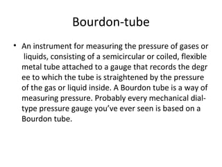


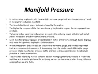
![MANIFOLD PRESSURE GAUGE
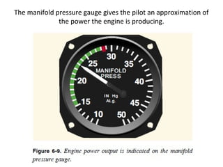
• The absolute pressure inside the induction system of an engine is an important indicator of the
power the engine is developing. Although this manifold pressure is not directly proportional to
horsepower, it is related qualitatively. In a normally aspirated [non-supercharged] engine, the
maximum differen-tial between manifold pressure and atmospheric pressure will occur when
the engine is at idle. As the throttle is opened, manifold pressure rises and approaches
atmospheric pressure. When the throttle is wide open, the engine is producing maximum
manifold pressure and horsepower. The aircraft flight manual includes charts showing the
various combinations of r.p.m. and manifold pressures that produce desired engine
performance.
• For normally aspirated engines, the manifold pressure gauge usually has a range from 10 to
40 inches of mercury. For turbocharged engines, the range extends high enough to cover the
highest manifold pressure for which the engine is rated.](https://image.slidesharecdn.com/aircraftinstrumentsystems-130701081229-phpapp02/85/Aircraft-instrumentsystems-34-320.jpg)


The document discusses aircraft instrument systems. It describes the main types of instruments including flight instruments, engine instruments, and navigation instruments. It explains that flight instruments like the altimeter, airspeed indicator, and magnetic compass provide pilots with critical flight information. Engine instruments monitor parameters like fuel, oil, temperatures, and speeds. Navigation instruments help pilots navigate along a course and for approaches. Pressure measuring instruments are also discussed, with details on how Bourdon tubes are commonly used to sense and measure pressure in aircraft.


