Downloaded 323 times
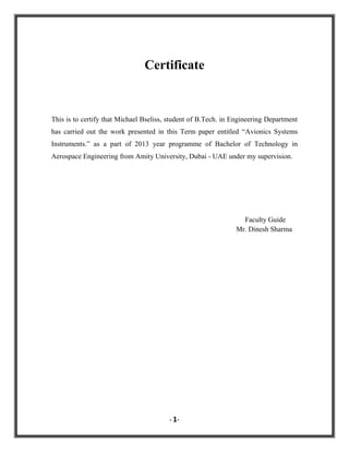
![The cockpit of an aircraft is an idealistic location for avionic equipment, including
monitoring, control, weather, navigation, communication and anti-collision systems.
The journalist Philip J. Klass was the founder of word avionics. Many modern avionics
have their origins in World War II wartime developments. Autopilot systems that are
fruitful today were started to help bomber planes fly steadily enough to hit precision
targets from high altitudes. Radar was developed in Germany, the United Kingdom and
the United States of America during this period. Modern avionics is essential portion of
military aircraft spending.
Most modern helicopters now have budget splits of 60/40 in favour of avionics.
The F‑15E and the now retired F‑14 aircrafts have almost 80 percent of their budget
spent on avionics. It‟s the same for the civilian market.
Flight control systems and new navigation needs brought on by tighter airspaces, have
pushed up development costs. [1] More accurate methods of controlling aircraft safely in
these high restrictive airspaces have been invented as more people begin to use planes as
their primary method of transportation.
Pilots of modern advanced avionics aircraft must learn and practice backup procedures to
maintain their skills and knowledge. Risk management principles require the flight crew
to always have a backup or alternative plan, and/or escape route. Advanced avionics
aircraft relieve pilots of much of the minute-to-minute tedium of everyday flights, but
demand much more initial and recurrent training to retain the skills and knowledge
necessary to respond adequately to failures and emergencies.
- 4-](https://image.slidesharecdn.com/termpaper-131214061328-phpapp02/85/Avionics-Systems-Instruments-4-320.jpg)
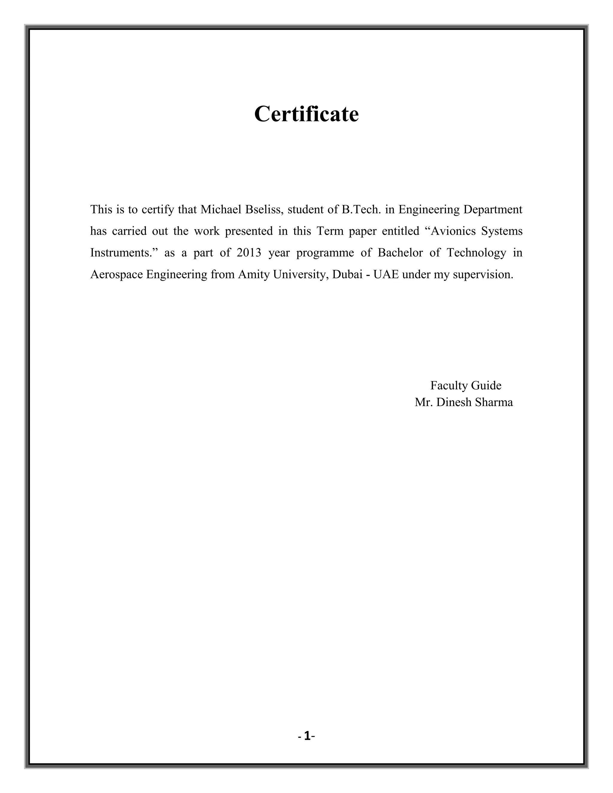
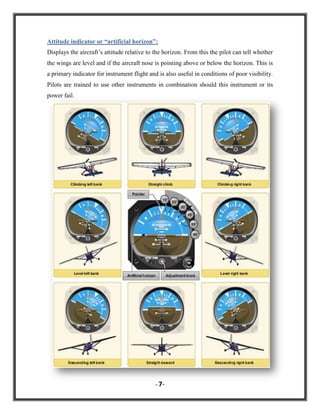
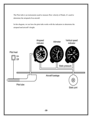
![Decisive between the flight instruments that are fitted in any aircraft, are those that
indicate the position and attitude of the aircraft. [5] These flight instruments are very
important to display information about:
• Heading
• Altitude
• Airspeed
• Rate of turn
• Rate of climb (or descent)
• Attitude (relative to the horizon).
Here we will talk in brief about the instruments that provide these indications:
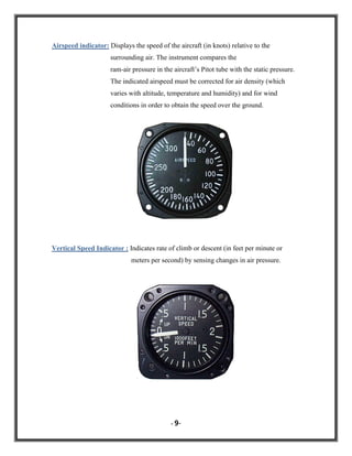
Altimeter: Indicates the aircraft‟s height (in feet or meters) above a reference level
(usually
mean
sea
level)
by
measuring
the
local
air
pressure.
To provide accurate readings the instrument is adjustable for local barometric
pressure.
In large aircraft a second standby altimeter is often available.
- 6-](https://image.slidesharecdn.com/termpaper-131214061328-phpapp02/85/Avionics-Systems-Instruments-6-320.jpg)
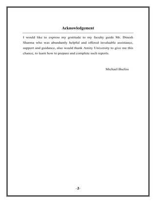
![In general, this system refers to equipment in charge of maintaining a comfortable close
environment for a given payload (goods, living matter, and people), i.e. keeping
temperature, pressure, and composition, within acceptable limits, usually by circulating a
fluid for thermal control and for life-support. [5] The ECS for vehicles in hostile
environments is most demanding: submarines, aircraft and spacecraft. The ECS usually
focuses on the inside part of the vehicle, whereas the environmental control of the outer
side is usually named environmental protection system (EPS).
This system work in the aircraft to provide air supply, thermal control and cabin
pressurization for the crew and passengers. Also avionics cooling, fire suppression and
smoke detection are considered as part of an aircraft's environmental control system.
- 11-](https://image.slidesharecdn.com/termpaper-131214061328-phpapp02/85/Avionics-Systems-Instruments-11-320.jpg)
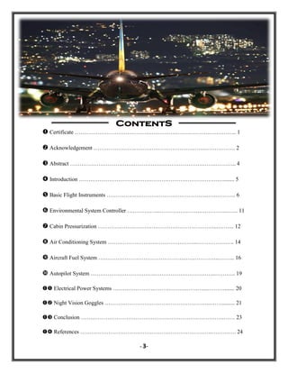
![A system which ensures the safety and comfort of passengers and crew by controlling the
cabin pressure and the exchange of air from the inside of the aircraft to the outside.
[6] This happens by pumping conditioned air into the cabin. This air is usually bled off
from the engines at the compressor stage. The air is then cooled, humidified, mixed with
recirculated air if necessary and distributed to the cabin by one or more environmental
control systems. The cabin pressure is regulated by the outflow valve.
On most planes, cabin pressurization begins as soon as the wheels leave the ground. The
engines begin sucking in air from the outside and funneling that air through a series of
chambers. This both heats the air and pressurizes it. Before the air can be forced into the
cabin, it must be cooled, which happens in what is known as an air cycle cooler. Air from
this cooler flows constantly into the cabin through an overflow valve.
Aircraft engines become more efficient with increase in altitude, burning less fuel for a
given airspeed. In addition, by flying above weather and associated turbulence, the flight
- 12-](https://image.slidesharecdn.com/termpaper-131214061328-phpapp02/85/Avionics-Systems-Instruments-12-320.jpg)
![Any aircraft must be equipped with an air conditioning and pressurization system to fly at
high altitudes, which provides a convenient environment for its passengers. The human
body is unable to withstand the effects of a low-pressure atmosphere, that‟s why the AC
and pressurization system is a vital component of modern flight.
Aircraft AC systems are very similar on all modern airplanes. [3] However, I will
mention a brief explanation about this system in the A 320 Airbus.
The system is basically comprised of air conditioning packs, a pack flow control valve, a
by-pass valve, pack controllers, and a mixing unit.
These components provide conditioned air via the following step by step process:
1. Outside air enters the airplane engine.
2. Next, compressors within the engine compress this low-density air.
3. Bleed air (hot compressed air from the compressor) is then transported via ducts
to the AC packs.
4. Before entering the air conditioner units, the bleed air passes through the pack
flow control valve, which regulates the flow of air entering the conditioning
packs.
5. Within the AC unit, two air-to-air heat exchangers are installed that supply
outside air via a pack inlet scoop and the air exits through an outlet duct.
6. As the cold air exits from the conditioning pack, it is mixed with warm air.
7. The desired air temperature is achieved by regulating the amount of hot air
mixed with the cold conditioned air exiting from the packs through a by-pass
valve.
8. The regulated air is then fed to a mixing unit which transports the air further on
into the cabin and the cockpit.
9. The by-pass valve, pack flow control valve, inlet scoop and outlet duct are all
operated by, and connected to, a pack controller.
- 14-](https://image.slidesharecdn.com/termpaper-131214061328-phpapp02/85/Avionics-Systems-Instruments-14-320.jpg)
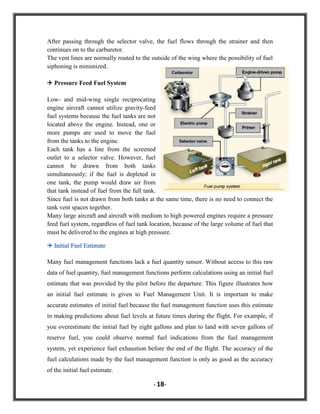
![An aircraft Fuel System enables fuel to be loaded, stored, managed and delivered to the
propulsion system of an aircraft and Fuel management systems are used to control,
monitor and maintain fuel consumption and stock in any type of industry that uses
transport, including rail, road, water and air.
A fuel management system helps to make the fuel calculations needed for in-flight
decisions about diversions, potential routing, and fuel stops. [8] A fuel management
system offers the advantage of precise fuel calculations based on distance, winds, time
and fuel flow measured by other aircraft systems.
High performance aircraft fuel systems manage complex operations like highly accurate
fuel measuring, weight, balance, fuel transfer between tanks and air-to-air and ground
refueling for commercial, military and space applications.
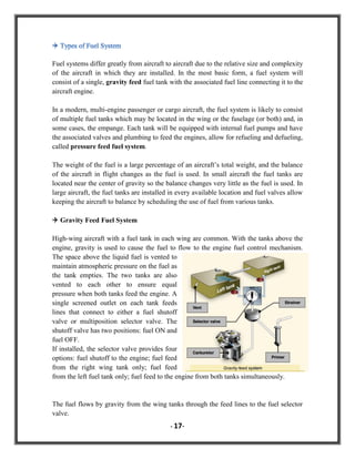
Aircrafts usually have several fuel tanks, and there are fuel transfers among these tanks
along a flight. These transfers are controlled with valves, and may follow several
alternative paths.
1This figure shows a typical fuel tank layout for a
commercial aircraft. Wing structure is a common
location for fuel storage and in many commercial
transports additional tanks are located in the area
between the wings. Longer range aircraft and
business jets may have tail tanks and/or additional
fuselage tanks; however, in most cases the fuselage is
primarily the place for passengers, cargo, flight deck
(cockpit) and avionics equipment. Military fighters
are a special case and while the wing space is used
for fuel storage in these applications, almost any
available space in the fuselage may be used for fuel.
- 16-](https://image.slidesharecdn.com/termpaper-131214061328-phpapp02/85/Avionics-Systems-Instruments-16-320.jpg)
![The automatic pilot is a system of automatic controls which holds the aircraft on any
selected magnetic heading and returns the aircraft to that heading when it is displaced
from it. The automatic pilot also keeps the aircraft stabilized around its horizontal and
lateral axes.
The purpose of autopilot system is primarily to reduce the strain, work and fatigue of
controlling the aircraft during long flights. [4] To do this, the automatic pilot system
performs many functions. It allows the pilot to maneuver the aircraft with a minimum of
manual operations. While under automatic control, the aircraft can be made to climb, turn
and dive with small movements of the knobs on the autopilot controller.
Autopilot systems provide for one, two or three axis control of the aircraft. Some
autopilot systems control only the ailerons (one axis), others control ailerons and
elevators or rudder (two axes). The three-axis system controls ailerons, elevators and
rudder.
All autopilot systems contain the same basic components:
1. Gyro: to sense what the aircraft is doing.
2. Servo: to move the control surfaces.
3. An amplifier: to increase the strength of gyro signals enough to operate the servos.
4. A controller: to allow manual control of the aircraft through the autopilot system.
The automatic pilot system flies the aircraft by using electrical signals developed in gyrosensing units. These units are connected to flight instruments which indicate direction,
rate-of-turn, bank or pitch. If the flight altitude or magnetic heading is changed, electrical
signals are developed in the gyros. These signals are used to control the operation of
servo units which convert electrical signals into mechanical force which moves the
control surface (ailerons and elevators or rudder) in response to corrective signals or pilot
commands.
- 19-](https://image.slidesharecdn.com/termpaper-131214061328-phpapp02/85/Avionics-Systems-Instruments-19-320.jpg)
![An aircraft Electrical System is a network of components that generate, transmit,
distribute, utilize and store electrical energy.
An electrical system is an essential component of all but the most simplistic of aircraft
designs. [7] The electrical system capacity and complexity varies tremendously between
a light, piston powered, single engine aircraft and a modern, multiengine commercial jet
aircraft. However, the electrical system for aircraft at both ends of the complexity
spectrum share many of the same basic components.
All aircraft electrical systems have components with the ability to generate electricity.
Depending upon the aircraft, generators or alternators are used to produce electricity.
One of the uses of the generator output is to charge the aircraft battery(s).
Batteries are normally either lead-acid or another type and are used for both aircraft
startup and as an emergency source of power in the event of a generation or distribution
system failure.
The Electrical Power Systems (EPS) in future more-electric aircrafts (MEA) will undergo
significant
changes.
functions
that used to be
operated
by
pneumatic
and mechanical
power are
being
replaced
by electric
power
due to
recent
advances
power
Many
hydraulic,
in
electronics,
electric drives, control electronics and microprocessors, improving the performance and
the reliability of the aircraft EPS, reducing fuel consumption per passenger per mile and
increasing the availability of the aircraft.
- 20-](https://image.slidesharecdn.com/termpaper-131214061328-phpapp02/85/Avionics-Systems-Instruments-20-320.jpg)
![For safe and effective flight, visual reference to the aviator‟s outside world is essential.
During the daylight hours and in visual meteorological conditions (VMC), the pilot relies
heavily on the out-the-windshield view of the airspace and terrain for situational
awareness.
In addition, the pilot‟s visual system is augmented by the avionics which provide
navigation, mission, communication, flight control and aircraft systems information.
During nighttime VMC, the pilot can improve the out-the-windshield view with the use
of night vision goggles (NVG).
NVG lets the pilot see in the dark during VMC conditions.
NVG are electronic widgets that allow
the pilot to see things at night when it is
too dark to see things with the eyes
alone.
NVG
are
light
image
intensification devices that amplify the
night-ambient-illuminated scenes by a
factor of 104. [2] For this application
“light” includes visual light and near
infrared. NVG are miniature packaging
of image intensifiers into a small,
lightweight, helmet-mounted pair of
goggles.
With the NVG, the pilot views the
outside scene as a green phosphor
image displayed in the eyepieces.
- 21-](https://image.slidesharecdn.com/termpaper-131214061328-phpapp02/85/Avionics-Systems-Instruments-21-320.jpg)
![[1] Cary R. Spitzer, Avionics: Development and Implementation.
[2] Albert Helfrick & Len Buckwalter, Principles of Avionics, 4th Edition, Avionics
Communications Inc. (Paperback - Jul 1, 2007)
[3] NASA Glenn Research Center. Air Density. Accessed February 21, 2012, Air
conditioning system.
[4] Federal Aviation Administration, Airframe & Powerplant Mechanics -15 A.
[5] Richard C. Dorf, The Avionics Handbook.
[6] Brain, Marshall (April 12, 2011), How Airplane Cabin Pressurization Work.
[7] J. Weimer, Electrical power technology for the more electric aircraft, in
Conference Proceedings of IEEE DASC‟ 1993, vol. 3, pp.445-450, 1993.
[8] Roy Longton, Chuck Clark, Martin Hewitt and Lonnie Richards, Aircraft Fuel
Systems.
=======================
====================
=================
=============
- 24-](https://image.slidesharecdn.com/termpaper-131214061328-phpapp02/85/Avionics-Systems-Instruments-24-320.jpg)

The document is a term paper by Michael Bseliss on avionics systems instruments as part of a B.Tech program at Amity University. It discusses the importance of avionics in modern aircraft, detailing various systems such as flight instruments, environmental control, air conditioning, and fuel management. The paper emphasizes the necessity of electronic systems for aircraft operation and the role they play in ensuring safety and efficiency in aviation.


